

Page 1
i
Page 2

Page 3

i
Preface
©2008 MPC Corporation (“MPC”). MPC is not responsible for
omissions or errors in typography or photography. All screen
images are simulated unless otherwise indicated. All offers are
subject to availability. Prices and specifications may change
without notice; prices do not include shipping, handling or
applicable taxes, unless contractually required. Phone charges
may apply for tech support. MPC's return policy does not include
return freight and original shipping/handling charges, and a
restocking fee may be charged. All return and warranty periods
begin on shipping date. All sales are controlled by MPC's current
terms and conditions of sale and limited warranty, available on
MPC's website or from its sales representatives. On-site service is
provided at MPC’s sole discretion. A qualifying diagnostic
determination must be made by MPC prior to on-site service (if
any). On-site service is provided by a third-party service provider
under a separate contract between customer and service provider.
Advertised configurations may differ from award-winning
configurations. Customer processor performance may vary. Atom,
Celeron, Celeron Inside, Centrino, Centrino Inside, Centrino Logo,
Core Inside, Intel, Intel Logo, Intel Core, Intel Inside, Intel Inside
Logo, Intel Viiv, Intel vPro, Itanium, Itanium Inside, Pentium,
Pentium Inside, Viiv Inside, vPro Inside, Xeon, and Xeon Inside are
trademarks of Intel Corporation in the U.S. and other countries.
Windows is a registered trademark of Microsoft Corporation in the
United States and other countries. Other product names are for
identification purposes only and may be trademarks of their
respective companies. 1GB equals 1 billion bytes. 56K modems
capable of downloading at up to 56Kbps and sending at up to
31.2Kbps. FCC regulations limit receiving speeds to 53Kbps.
Actual speeds may vary. 52X = 52X max./17X min. 48X=48X
max./17X min. 24X = 24X max./10X min. 8X DVD = 8X max./1X
min.
EMA001149-00
8/25/08, mlw
Page 4

ii
Table of Contents
ATTENTION: TEACHERS, PARENTS AND ADULT SUPERVISORS .................. 1
FEDERAL COMMUNICATIONS COMMISSION NOTICE ................................... 3
AGENCY REGULATORY NOTICES ............................................................. 3
MODIFICATIONS ...................................................................................... 4
CONNECTIONS TO PERIPHERAL DEVICES ...................................................... 4
SAR EXPOSURE ...................................................................................... 4
DECLARATION OF CONFORMITY ................................................................. 4
EUROPEAN NOTICE ................................................................................. 4
CANADIAN NOTICE .................................................................................. 5
ATTACHMENT LIMITATIONS STATEMENT ...................................................... 5
POWER CORD REQUIREMENT ..................................................................... 6
U.S. AND CANADA .................................................................................. 7
Other Countries .................................................................................... 7
BATTERY PACK SAFETY............................................................................ 7
LITHIUM BATTERY WARNING / BRIDGE BATTERY WARNING .............................. 8
WELCOME TO THE MPC TXTBOOK™ PC ................................................ 9
GETTING TO KNOW YOUR COMPUTER ...................................................... 9
OPENING THE LCD PANEL ........................................................................ 9
GETTING TO KNOW THE BASICS .............................................................. 9
FRONT VIEW ....................................................................................... 10
SYSTEM & POWER STATUS INDICATORS ..................................................... 11
LEFT VIEWS ........................................................................................ 14
RIGHT VIEW ........................................................................................ 15
BOTTOM VIEW ..................................................................................... 17
CONNECTING TO A POWER SOURCE ...................................................... 18
CONNECTING THE AC ADAPTER ............................................................... 18
GETTING STARTED ............................................................................... 18
TURNING ON YOUR COMPUTER ............................................................. 19
OPERATING ON BATTERY POWER .......................................................... 19
THE BATTERY PACK ............................................................................. 20
Page 5

iii
TO INSTALL THE BATTERY PACK: ............................................................. 20
TO REMOVE THE BATTERY PACK: ............................................................ 21
LITHIUM-ION BATTERY .......................................................................... 21
BATTERY LOW-POWER WARNING ............................................................ 21
CHARGING THE BATTERY AND CHARGING TIME ........................................... 22
CHECKING THE BATTERY LEVEL ............................................................... 23
PROLONGING THE BATTERY’S LIFE AND USAGE CYCLES ................................ 23
USING POWER OPTIONS ........................................................................ 23
SUSPEND MODE ................................................................................... 24
STANDBY SUSPEND ................................................................................ 24
HIBERNATE SUSPEND ............................................................................. 24
POWER BUTTON ACTION ....................................................................... 24
ADJUSTING THE LCD SCREEN DISPLAY................................................. 25
LCD CARE .......................................................................................... 25
USING MPCTXTBOOK PC REFRESH ..................................................... 25
MPC TXTBOOK™ PC REFRESH HOT KEY CONTROLS........................... 26
FUNCTION KEYS (QUICK KEYS) .......................................................... 26
THE TOUCH PAD ................................................................................... 26
TOUCH PAD PRECAUTIONS ..................................................................... 27
RESETTING THE SYSTEM ....................................................................... 27
WEB CAMERA APPLICATION ................................................................. 28
WEB CAMERA APPLICATION ................................................................. 28
Open Folder ......................................................................................... 29
Snapshot ............................................................................................... 29
Record .................................................................................................. 29
THE TROUBLESHOOTING ACTIVITY SHOULD ONLY BE PERFORMED BY AN
ADULT. ................................................................................................. 30
TROUBLESHOOTING .............................................................................. 30
AUDIO PROBLEMS ................................................................................ 31
NO SPEAKER OUTPUT ............................................................................ 31
SOUND CANNOT BE RECORDED. ............................................................... 31
Page 6

iv
HARD DISK PROBLEMS ......................................................................... 32
THE HARD DRIVE IS MAKING ABNORMAL WHINING NOISES. .............................. 32
THE HARD DISK DRIVE HAS REACHED ITS CAPACITY. ...................................... 32
THE HARD DISK TAKES LONGER TO READ A FILE. .......................................... 32
DISPLAY PROBLEMS ............................................................................. 33
THE DISPLAY PANEL IS BLANK WHEN THE SYSTEM IS TURNED ON. .................... 33
THE SCREEN FLICKERS. .......................................................................... 33
KEYBOARD AND TOUCH PAD PROBLEMS ............................................... 33
THE BUILT-IN TOUCH PAD PERFORMS ERRATICALLY. ..................................... 33
THE BUILT-IN KEYBOARD ACCEPTS NO INPUT. ............................................. 33
THE CHARACTERS ON THE SCREEN REPEAT WHILE I TYPE. ............................. 33
MEMORY PROBLEMS ............................................................................. 34
THE O/S ISSUES AN INSUFFICIENT MEMORY ERROR MESSAGE DURING OPERATION.
........................................................................................................ 34
NETWORK ADAPTER / ETHERNET PROBLEMS ......................................... 34
THE ETHERNET ADAPTER DOES NOT WORK................................................. 34
THE ETHERNET ADAPTER DOES NOT APPEAR TO OPERATE IN THE 100MBPS
TRANSMISSION MODE. ............................................................................ 34
PERFORMANCE PROBLEMS ................................................................... 34
THE COMPUTER BECOMES HOT. ............................................................... 34
THE PROGRAM APPEARS STOPPED OR RUNS VERY SLOWLY. ............................ 35
USB2.0 PROBLEMS.............................................................................. 35
THE USB DEVICE DOES NOT WORK. .......................................................... 35
ENTERING THE BIOS SETUP SCREEN .................................................... 36
LEAVING THE BIOS SETUP SCREEN ...................................................... 36
BIOS SETUP AND SECURITY FEATURE .................................................. 36
BIOS ACTION KEYS ............................................................................. 37
MODIFYING THE BIOS SETTINGS ........................................................... 37
MAIN SETUP ........................................................................................ 38
ADVANCED SETUP ................................................................................. 39
SECURITY ............................................................................................ 42
Page 7

v
USING PASSWORD PROTECTION ............................................................ 42
BOOT SETUP ..................................................................................... 43
EXIT SETUP ...................................................................................... 46
SPECIFICATION ..................................................................................... 47
CPU ....................................................................................................... 47
Memory ................................................................................................ 47
Core Logic ............................................................................................ 47
Audio Codec......................................................................................... 47
Card reader (2 in 1) ........................................................................... 47
LAN Controller .................................................................................... 47
Wireless LAN ....................................................................................... 47
Keyboard .............................................................................................. 47
Pointing Device ................................................................................... 48
Camera ................................................................................................. 48
Storage ................................................................................................. 48
LCD ........................................................................................................ 48
Battery Pack ........................................................................................ 48
AC-Adapter .......................................................................................... 48
BIOS ....................................................................................................... 49
Physical Outline .................................................................................. 49
EMC ....................................................................................................... 49
RF .......................................................................................................... 49
Safety ................................................................................................... 49
ENERGY STAR 4.0 ................................................................................ 49
EPEAT SILVER…………….……………………………...….……......49
SERVICE AND SUPPORT ........................................................................ 49
Page 8

Page 9
1
Please ensure that students understand the
following:
Emphasize to student that this device is an educational
tool and not a toy. The computer, power supply,
battery pack or power cord should not be dropped,
crushed, stepped on or otherwise abused.
This product is intended for school age children, ages 5
and up.
Ensure students understand the safe and proper
handling of power cord and power supply. Misuse could
result in serious injury.
Use caution when using this computer
around younger children. Keep power cords and small
accessories away from younger children. If computer is
damaged, keep any resulting small parts (such as a
keyboard key) away from younger children and report
damage or loose parts to their teacher, parent or adult
supervisor immediately.
The teacher, parent or adult supervisor should
periodically inspect the computer, power supply and
power cord for damage and replace, if necessary.
Caution students to avoid using device in wet
conditions and to protect the unit when carrying in wet
conditions.
When cleaning the unit, clean only with a slightly
damp soft cloth. Do not pour liquid onto the unit. Do
not clean while computer is “on” or plugged into wall
AAtttteennttiioonn:: TTeeaacchheerrss,, PPaarreennttss aanndd
AAdduulltt SSuuppeerrvviissoorrss
Page 10

2
socket.
Do not leave PC plugged in or “on” when enclosed in a
non-vented container, such as a school backpack, as
overheating may occur.
It is recommended that students take a 5 minute break
every 30 minutes of use.
Page 11

3
FFeeddeerraall CCoommmmuunniiccaattiioonnss CCoommmmiissssiioonn NNoottiiccee
This equipment has been tested and found to comply with
the limits for a Class B digital device, pursuant to Part 15 of
the FCC Rules. These limits are designed to provide
reasonable protection against harmful interference in a
residential installation. This equipment generates, uses,
and can radiate radio frequency energy and, if not installed
and used in accordance with the instructions, may cause
harmful interference to radio communications. However,
there is no guarantee that interference will not occur in a
particular installation. If this equipment does cause
harmful interference to radio or television reception, which
can be determined by turning the equipment off and on,
the user is encouraged to try to correct the interference by
one or more of the following measures:
Reorient or relocate the receiving antenna.
Increase the separation between the equipment and
the receiver.
Connect the equipment into an outlet on a circuit
different from that to which the receiver is connected.
Consult the dealer or an experienced radio or
television technician for help.
AAggeennccyy RReegguullaattoorryy NNoottiicceess
Page 12

4
This transmitter must not be
co-located or operating in conjunction with any other
antenna or transmitter.
Modifications
The FCC requires the user to be notified that any changes
or modifications made to this device that are not expressly
approved by the manufacturer may void the user’s
authority to operate the equipment.
Connections to Peripheral Devices
Connections to this device must be made with shielded
cables with metallic RFI/EMI connector hoods to maintain
compliance with FCC Rules and Regulations.
SAR Exposure
MPC TXTbook™ PC refresh has been tested for and found to
be in compliance with FCC RF Exposure Limit. During
extended periods of use the integrated antenna located at
the top left corner of the display screen should be
positioned at least 20cm from users or nearby persons.
Declaration of Conformity
This device complies with Part 15 the FCC Rules. Operation
is subject to the following two conditions: (1) this device
may not cause harmful interference, and (2) this device
must accept any interference received, including
interference that may cause undesired operation.
European Notice
Products with the CE Marking comply with both the EMC
Directive (2004/108/EC) and the Low Voltage Directive
(2006/95/EC) and R&TTE Directive (1999/5/EC) issued by
the Commission of the European Community.
Compliance with these directives implies conformity to the
following European Norms:
Page 13
5
EN55022: 2006, CLASS B
EN61000-3-2: 2006, CLASS D
EN61000-3-3: 1995+A1: 2001+A2: 2005
EN55024: 1998+A1: 2001+A2: 2003
IEC61000-4-2: 2001 ED. 1.2
IEC61000-4-3: 2006 ED. 3.0
IEC61000-4-4: 2004 ED. 2.0
IEC61000-4-5: 2005 ED. 2.0
IEC61000-4-6: 2006 ED. 2.2
IEC61000-4-8: 2001 ED. 1.1
IEC61000-4-11: 2004 ED. 2.0
EN 300 328-2, EN 300 328-1, EN 301 489-1, EN 301 489-
17 (ETSI 300 328, ETSI 301 489) Electro-magnetic
Compatibility and Radio Spectrum Matter.
TBR21 (ETSI TBR21) Terminal Equipment.
EN60950 (IEC60950) I.T.E. Product Safety
Canadian Notice
This digital apparatus does not exceed the Class B limits for
radio noise emissions from digital apparatus as set out in
the radio interference regulations of the Canadian
Department of Communications.
Le present appareil numerique nemet pas de bruits
radioelectriques depassant les limites applicables aux
appareils numeriques de Classe B prescrites dans le
reglement sur le brouillage radioelectrique edicte par le
Ministere des Communications du Canada.
Attachment Limitations Statement
This equipment meets
telecommunications network protective, operational and
safety requirements as prescribed in the appropriate
Terminal Equipment Technical Requirements
document(s).
Page 14

6
This is confirmed by marking the equipment with the
Industry Canada certification number. The Department
does not guarantee the equipment will operate to the user's
satisfaction.
Before installing this equipment, users should ensure that it
is permissible to be connected to the facilities of the local
telecommunications company.
The equipment must also be installed using an acceptable
method of connection. The customer should be aware that
compliance with the above conditions may not prevent
degradation of service in some situations.
Repairs to certified equipment should be coordinated by a
representative designated by the supplier. Any repairs or
alterations made by the user to this equipment, or
equipment malfunctions, may give the telecommunications
company cause to request the user to disconnect the
equipment.
Users should ensure for their own protection that the
electrical ground connections of the power utility,
telephone lines and internal metallic water pipe system, if
present, are connected together. This precaution may be
particularly important in rural areas.
Users should not attempt to make
such connections themselves, but should contact the
appropriate electric inspection authority, or electrician,
as appropriate.
Power Cord Requirement
The power cord supplied with the AC adapter should match
the plug and voltage requirements for your local area.
Regulatory approval for the AC adapter has been obtained
using the power cord for the local area.
However, if you travel to a different area and need to
connect to a different outlet or voltage, you should use one
of the power cords listed below. To purchase a power cord
Page 15
7
(including one for a country not listed below) or a
replacement AC adapter, contact your local dealer.
U.S. and Canada
The cord set must be UL/ETL-Listed and CSA-Certified
or UL/C-ETL Listed.
The minimum specifications for the flexible cord are (1)
No. 18 AWG, (2) Type SPT-2, and (3) 2-conductor.
The cord set must have a rated current capacity of at
least 7A.
The attachment plug must be NEMA 1-15P (7A, 125V)
configuration.
Other Countries
The cord set fittings must bear the certification mark
of the agency responsible for evaluation in a specific
country. Acceptable agencies are:
CCC (China)
The flexible cord must be of a HAR (harmonized) type
HO5VV-F 3-conductor cord with a minimum conductor
size of 0.03 square inches.
The minimum specification for the flexible cord for
Class II product are: (1) 2X0.75 mm2 conductors, (2) 2conductor cord.
The cord set must have a current capacity of at least
10 A and a nominal voltage rating of 125 / 250 VAC.
This model IS DESIGNED TO USE WITH
THE FOLLOWING AC ADAPTER MODEL ONLY
Manufacturer: LI SHIN INTERNATIONAL ENTERPRISE
CORP.
Manufacturer: Delta
Battery Pack Safety
The battery pack is intended to use only with this
notebook.
The battery pack should be replaceable by the end user.
Page 16
8
Only qualified service technicians should replace the
battery pack.
Do not disassemble the pack.
Do not dispose of the battery pack in fire or water.
To avoid risk of fire, burns, or damage to your battery
pack, do not allow a metal object to touch the battery
contacts.
Handle a damaged or leaking battery with extreme
care. If you come in contact with the electrolyte, wash
the exposed area with soap and water. If it contacts
the eye, flush the eye with water for 15 minutes and
seek medical attention.
Do not charge the battery pack if the ambient
temperature exceeds 40℃C (113℉F).
To obtain a replacement battery, contact your local
dealer.
Do not expose the battery pack to high storage
temperatures above 60℃C (140℉F).
When discarding a battery pack, contact your local
waste disposal provider regarding local restrictions on
the disposal or recycling of batteries.
Use only supplied AC Adapter for charging.
Danger of explosion if battery is
incorrectly replaced. Only qualified service technicians
should replace and discard the battery pack. Replace
only with same or equivalent type recommended by the
manufacturer. Discard used batteries according to the
manufacturer’s instructions or local laws.
Lithium battery warning / Bridge battery warning
This computer contains a lithium battery to power the
clock and calendar circuitry.
This part is hot. Be careful.
This symbol indicates this part may be hot.
Page 17
9
WWeellccoommee ttoo tthhee MMPPCC TTXXTTbbooookk™™ PPCC
Congratulations on your purchase of the MPC TXTbook™ PC.
The MPC TXTbook™ PC features the latest advances in
portable computing technology. The MPC TXTbook™ PC
provides maximum expandability without compromising
portability.
GGeettttiinngg ttoo KKnnooww YYoouurr CCoommppuutteerr
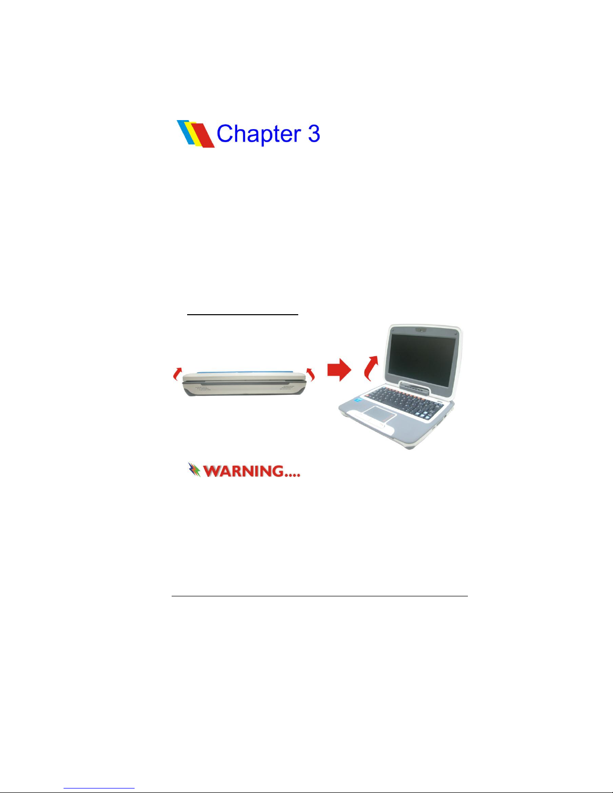
Opening the LCD Panel
To avoid damage to the display
panel:
1. Try not to slam the display when closing it.
2. Try not to place any object on top when it is closed or
open.
3. Be sure the system is turned off or in suspend mode
before you close the display panel.
With the LCD screen open, you will see several features
important for operating your MPC TXTbook™ PC.
GGeettttiinngg ttoo KKnnooww tthhee BBaassiiccss
Page 18
10
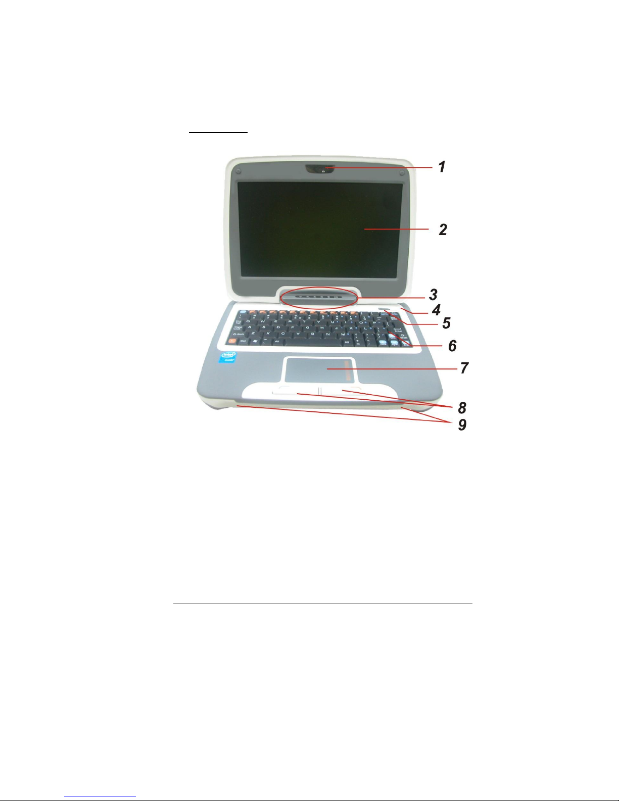
Front View
1. CCD Camera
Use this camera for any video conferencing application.
2. LCD Display
The panel is where the system content is displayed.
Page 19
11
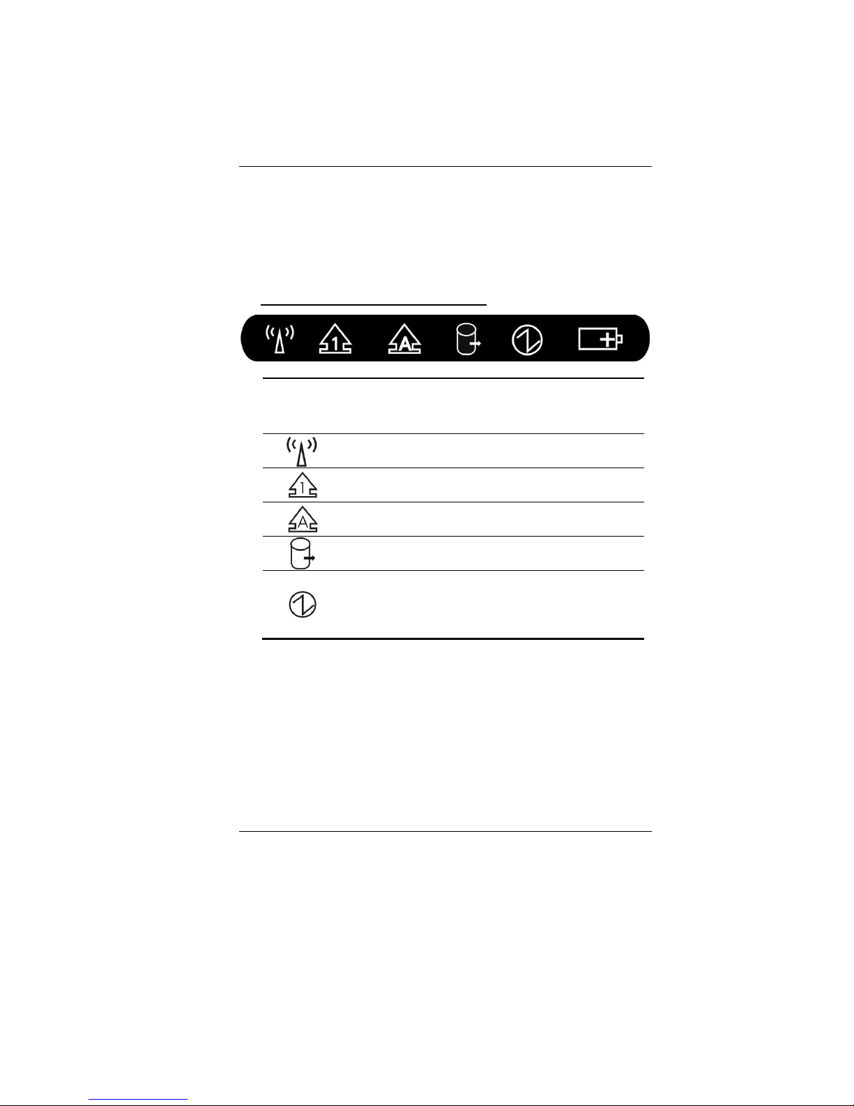
3. LED Status Indicator
The LED Status Indicator displays the operating status of
your MPC TXTbook™ PC. When a certain function is enabled,
a LED will light up. The following section describes the
indication.
System & Power Status Indicators
LED
Graphic
Symbol
Indication
Green light indicates the WLAN module is
active.
Green light indicates the numeric keypad is
activated.
Green light indicates the cap-lock is
activated.
Green light indicates the HDD is being
accessed.
Green light indicates the system is ON.
When light is flashing, this indicates the
system is in Standby.
Page 20

12
The battery LED reflects according to the
following status:
No light indicates that the battery pack is
not installed in your system.
Orange light indicates the battery is
being charged.
Blinking Orange light indicates the
battery power is low.
Green light indicates the battery is full
and the AC Adapter is plugged in.
When the LED reflects this status: green
light off orange light off
green light, this indicates the
battery’s temperature is too high.
4. Built-in Microphone
The microphone jack (3.5 mm diameter) is where you
connect a microphone.
Page 21
13
5. Power/Suspend Button
Press momentarily to turn on the system.
Press and hold for at least 4 seconds to turn off
the system.
Press the power/suspend button again to return
from the suspend mode.
Persistent green light indicates the Power is ON.
6. Keyboard
The keyboard is used to enter data.
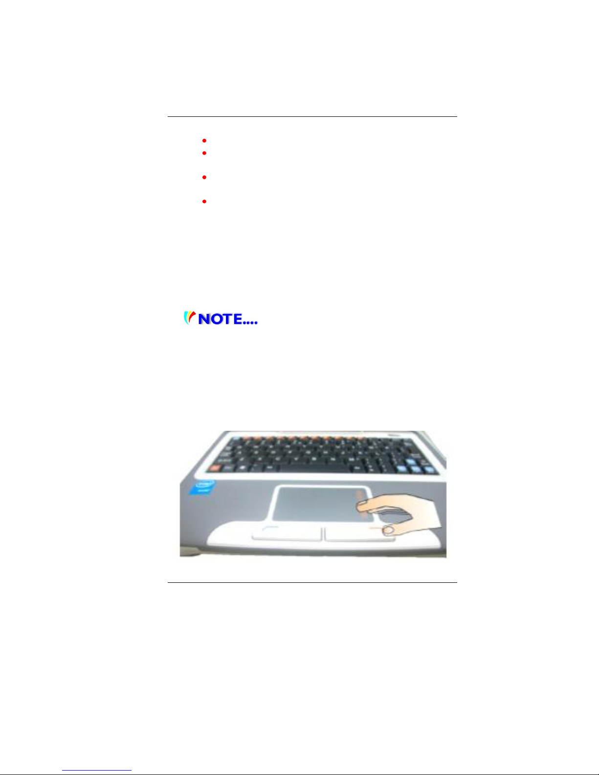
7. Touch Pad
The touch pad is a built-in pointing device with functions
similar to a mouse. (A mouse is a small mobile manual
device that controls movement of the cursor and selection
of functions on a computer display.)
The touch pad is also equipped with a
scroll bar so you can move around in a large document.
Scrolling Bar- Slides a horizontal or vertical presentation
of content, such as text, drawings, or images, across a
screen or display window. It is often used to show large
amounts of data that could not fit on the viewport all at
the same time.
Page 22
14
8. Touch Pad Buttons
The touch pad works like the two buttons on an ordinary
mouse--a small mobile manual device that controls
movement of the cursor and selection of functions on a
computer display.
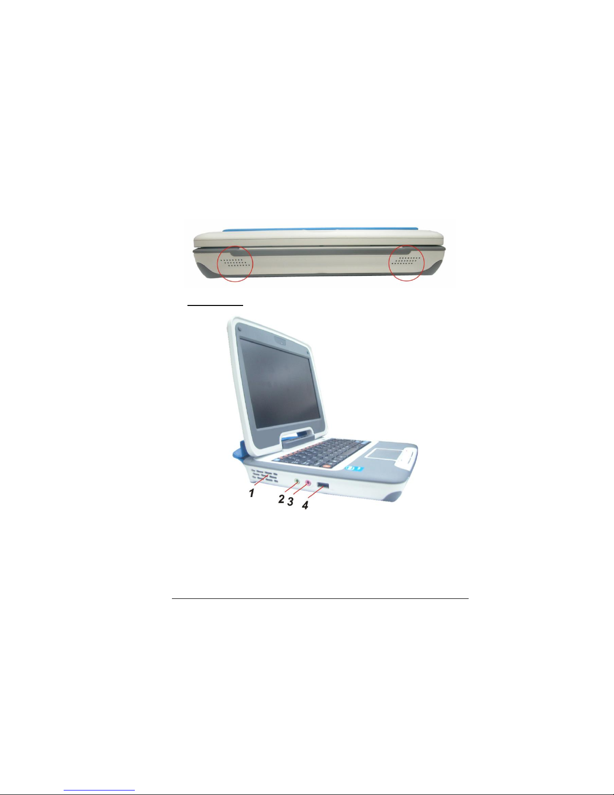
9. Built-in Stereo Speakers
The built-in speakers output the sound in stereo.
Left Views
1. Ventilation Grill
The fan grill is where air is exchanged to dissipate the
internal heat. Do not completely block this airway.
2. Stereo Headphone Jack
The stereo headphone jack (3.5 mm diameter) is where
you connect the headphones or external speakers.
Page 23
15
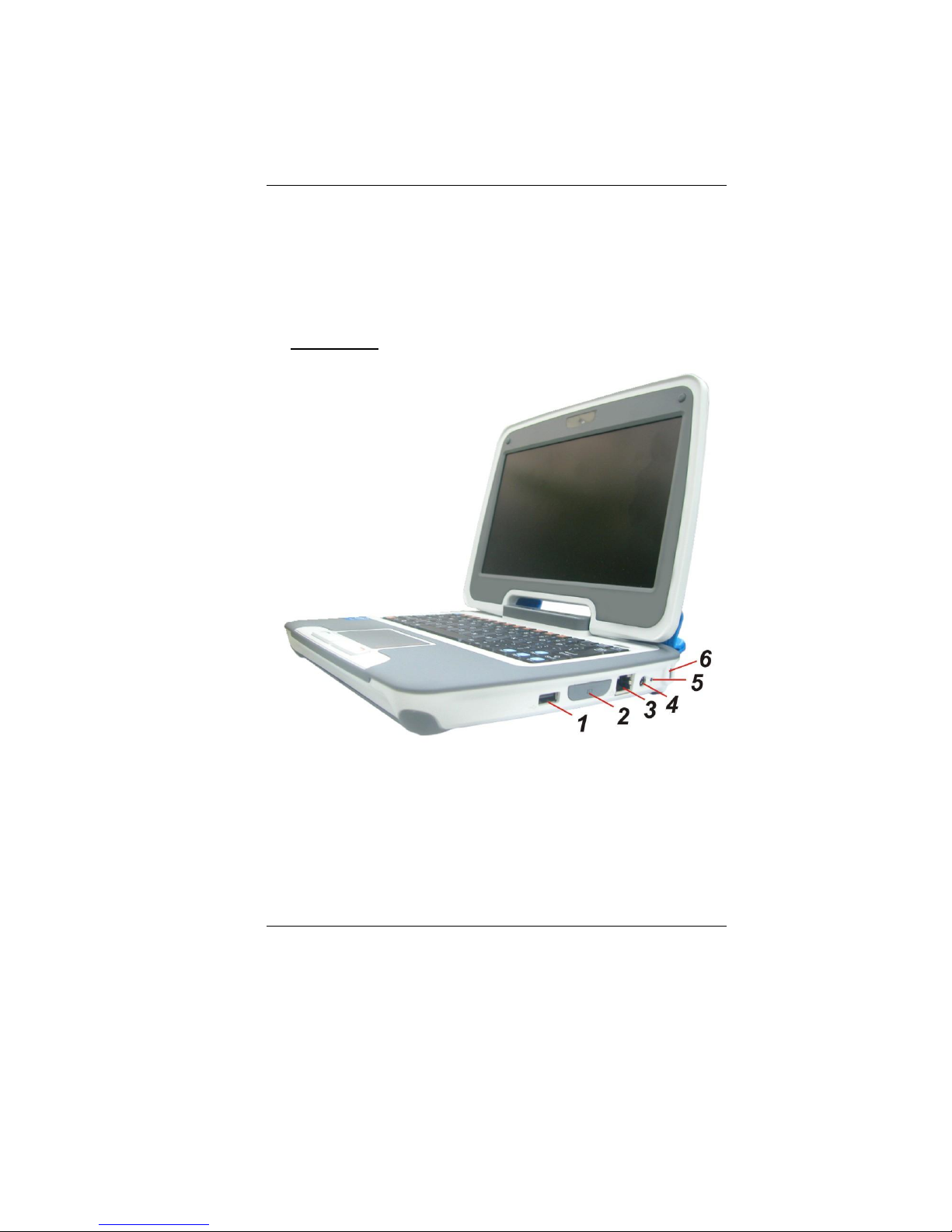
3. Microphone Jack
The microphone jack (3.5 mm diameter) is where you
connect a microphone.
4. USB 2.0 Port
This port conforms to the latest USB2.0 plug-and-play
standards.
Right View
1. USB 2.0 Ports
This port conforms to the latest USB2.0 plug-and-play
standards.
Page 24
16
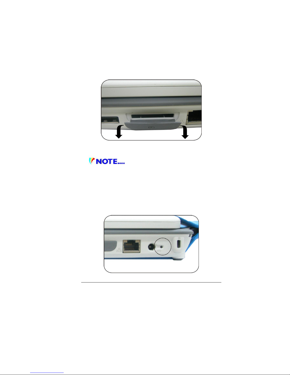
2. 2 in 1 Card Reader
The 2-in-1 Card Reader supports SD Card and MMC Card.
You need to remove the outer jacket to access the card
reader slot on the right side of the computer.
3. Ethernet / LAN Port
When using a LAN, please use an EMI
Shielding Cable to minimize an inteference when
transmitting.
4. Power Jack (DC-in)
The DC-out jack of the AC Adapter connects here and
powers the computer.
5. Power Indicator
This LED will blink in green color once the AC adapter is
connected.
Page 25
17
Light off indicates there is no battery attached.
Green light indicates the battery is fully charged.
Fast blinking (1sec/cycle) indicates the battery
temperature is high.
Blinking (2sec/cycle) indicates the battery is in
charging mode.
6. Kensington Lock
This security lock provides the best options for physical
security of computer in preventing the computer from
being stolen.
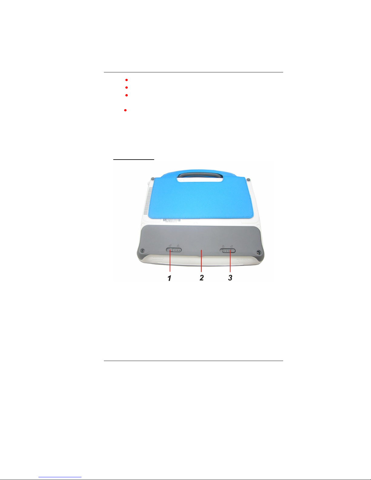
Bottom View
1. Battery Release Latch
Slide this latch to release the battery from its
compartment.
2. Battery Compartment
This compartment contains the battery pack of your
system.
3. Battery Lock/Unlock Latch
Slide this lock to lock or unlock the battery into its
compartment.
Page 26
18
CCoonnnneeccttiinngg ttoo aa PPoowweerr SSoouurrccee
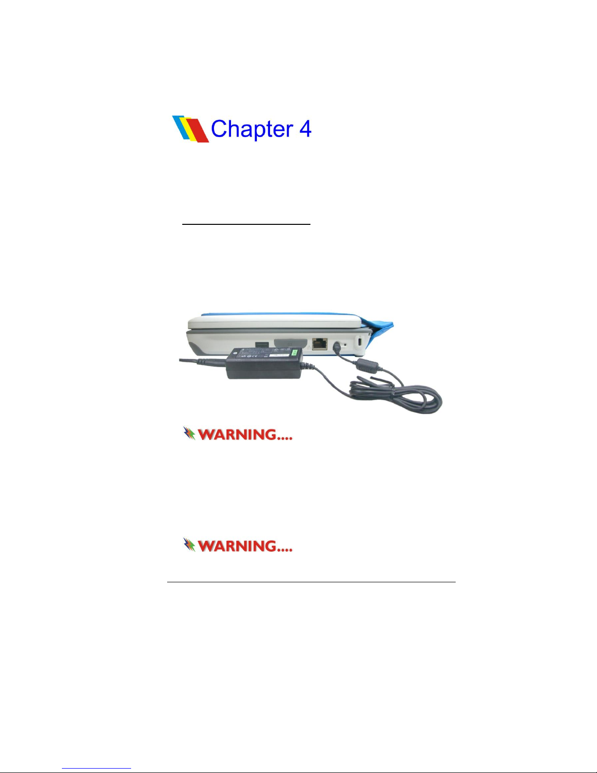
Connecting the AC Adapter
A universal AC adapter is provided to supply your computer
with power and also charge the computer’s battery pack.
The adapter’s AC input voltage can range anywhere from
100 to 240 volts, covering the standard voltages available in
almost every country. To connect the computer to an
external power source:
Do not use inferior extension
cords as this may result in damage to your MPC
TXTbook™ PC. The MPC TXTbook™ PC comes with its
own AC adapter. Do not use a different adapter to power
the computer and other electrical devices.
Whenever possible, keep the AC adapter plugged into the
MPC TXTbook™ PC and an electrical outlet to recharge the
battery.
Never turn off or reset your
MPC TXTbook™ PC while the hard disk is in use; doing so
GGeettttiinngg SSttaarrtteedd
Page 27

19
can result in loss or destruction of your data. Always
wait at least 5 seconds after turning off your MPC
TXTbook™ PC before turning it back on; turning the
power on and off in rapid succession can damage the
MPC TXTbook™ PC’s electrical circuitry.
TTuurrnniinngg OOnn YYoouurr CCoommppuutteerr
Turn on your MPC TXTbook™ PC by pressing the power
button. Hold the button down for a second or two and
release. The Power-On Self Test (POST) runs automatically.
After the POST is completed, the computer reads the
operating system from the hard disk drive into computer
memory (this is commonly referred to as “booting” a
computer). If your OS (Operating System such as Windows
XP, etc.) is installed, it should start automatically.
To turn the MPC TXTbook™ PC off, save your work and close
all open applications, click on Start, then Shut Down and
select Shut down the computer and click "Yes" or press
the power button for 4-6 seconds.
OOppeerraattiinngg oonn BBaatttteerryy PPoowweerr
Your computer comes with a rechargeable battery pack
that lets you operate the computer without an external
power source. When the battery pack is fully charged, you
can operate the computer under the following conditions:
The battery pack initially has a full charge.
No peripheral devices are installed.
Danger of explosion if battery is
incorrectly replaced. Replace only with same or
equivalent type recommended by the manufacturer.
Discard used batteries according to the manufacturer’s
instructions or local laws.
Page 28
20
TThhee BBaatttteerryy PPaacckk
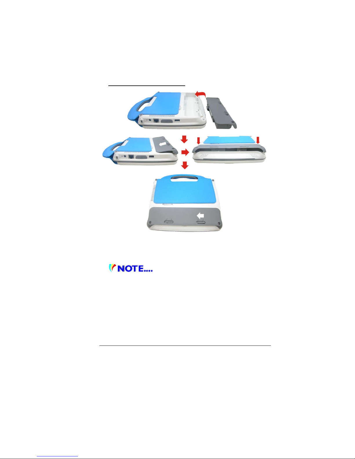
To Install the Battery Pack:
With the bottom facing up, slide the battery pack into the
battery compartment until it clicks and locks in place.
You must charge the battery pack for
at least six hours before using it for the first time.
In the Standby Suspend mode, a fully charged battery
loses its power in roughly 1/2 day or less. When not
being used, the battery’s power will deplete in one to
two months. The battery pack in this system is
replaceable by the end user.
Page 29
21
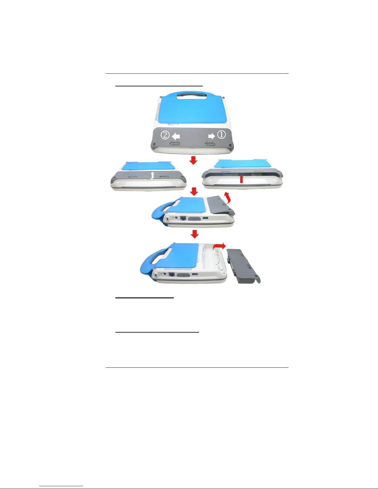
To Remove the Battery Pack:
Lithium-Ion Battery
Your MPC TXTbook™ PC uses a Lithium-Ion battery pack
that provides power when you don’t have access to an AC
outlet.
Battery Low-Power Warning
1. Low Battery Warning
Low battery condition occurs when battery power is
reduced to 10 percent. The orange battery status LED
Page 30
22
indicator blinks and the system beeps once every 16
seconds or so. (See Page 14 for indicator description.)
2. Very Low Battery Warning
Very Low battery condition occurs at 5 percent power
remaining. The orange battery status LED indicator blinks
and the system beeps at 4-second intervals.
When the MPC TXTbook™ PC warns you of its low battery
condition, you will have about three to five minutes to save
your current work.
Do not expose battery packs to
temperatures below 0 degree Celsius (32 degree F) or
above 60 degree C (140 degree F). This may adversely
affect the battery pack.
Charging the Battery and Charging Time
To charge the battery, plug the AC adapter into the MPC
TXTbook™ PC and an electrical outlet.
For a totally discharged battery, it will take approximately
two hours to charge to 90% capacity, and approximately
three hours to 100% capacity while MPC TXTbook™ PC is
powered OFF. It will take about 5 hrs to charge the battery
to 100% capacity while MPC TXTbook™ PC is powered on.
When the battery is fully charged, the battery charge
indicator becomes green.
If system runs at heavy loads or in a
high temperature environment, the battery may not be
fully charged. You need to continue to charge it with the
AC adapter plugged in until the charging LED turns
green.
System will not charge battery when
temperature exceeds 40C.
Page 31
23
Checking the Battery Level
You can check the remaining battery power in Operating
System battery status indicator.
Prolonging the Battery’s Life and Usage Cycles
There are ways you can prolong the use of battery.
Use the AC adapter wherever AC wall outlet is
available. This will ensure uninterrupted computing.
Store the battery pack in room temperature. Higher
temperature tends to deplete the battery’s power
faster.
Make good use of the power management function.
Save To Disk (Hibernate) saves the most energy by
storing current system contents in a hard disk space
reserved for this function.
The life expectancy of the battery is approximately
300 recharges.
See the notices section in the beginning of the user
manual on how to care for the battery pack.
Use Function+F9 key to decrease the brightness of the
screen.
To achieve optimal battery
performance, you may need to do a battery calibration
at a 3-month interval. To do this:
Fully charge the battery.
Then discharge the battery by entering the BIOS setup
screen. (Press DEL key as soon as you turn on the
computer.) Let it remain at the setup screen until the
battery runs out.
Fully charge the battery again.
UUssiinngg PPoowweerr OOppttiioonnss
Operating System Power Management provides basic power
saving features. In the power configuration dialogue box,
enter time-out values for the display and hard disk drive.
Page 32
24
For example: Operating System power manager saves
power by turning off hard drive after 1 minute of
inactivity.
Also consult Operating System user
guide for more information on how to use Operating
System power management functions.
SSuussppeenndd MMooddee
Standby Suspend
The system automatically enters this mode after a period
of inactivity, which is set in the Power Schemes dialog box.
In Standby mode, hardware devices, such as display panel
and hard disk, are turned off to conserve energy.
Hibernate Suspend
In this mode, all system data is saved in the hard disk
before powering down. When this mode is activated, all
system state and contents are saved to the hard disk drive
after a period of inactivity defined by the user.
No power or very little power is drawn from the battery
module under this mode.
However, depending on how much RAM that has been
installed on your computer, the amount of time the system
requires to restore all its previous contents can range from
five to 20 seconds.
PPoowweerr BBuuttttoonn AAccttiioonn
The MPC TXTbook™ PC refresh power button can be set to
turn off the system or activate the suspend mode. Press
the power button and release to wake the TXTbook from
standby or hibernation suspend state.
Page 33
25
AAddjjuussttiinngg tthhee LLCCDD SSccrreeeenn DDiissppllaayy
The LCD screen display can be adjusted by the following
key combinations.
KEYS
FUNCTIONS
Fn + F9
Decreases Display Brightness.
Fn +
F10
Increases Display Brightness.
LCD Care
LCD screens are delicate devices that need careful handling.
Please pay attention to the following precautions:
When you are not using the computer, keep the LCD
screen closed to protect it from dust.
If you need to clean your LCD screen, use a soft tissue
to gently wipe the LCD surface.
Do not put your fingers or sharp objects directly on the
surface and never spray cleaner directly onto the
display.
Do not press on, or store any objects on the cover
when it is closed. Doing so may cause the LCD to
break.
UUssiinngg MMPPCCTTXXTTbbooookk PPCC RReeffrreesshh
Page 34
26
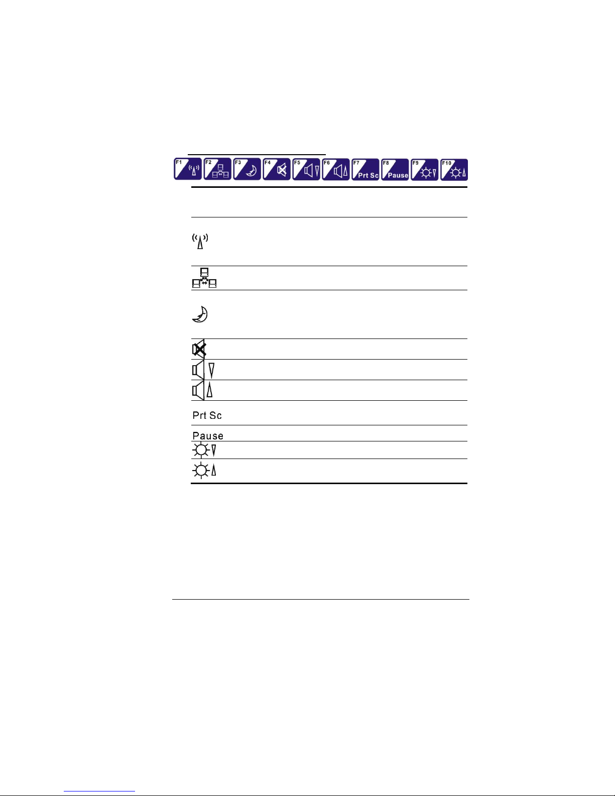
MMPPCC TTXXTTbbooookk™™ PPCC RReeffrreesshh HHoott KKeeyy CCoonnttrroollss
Function Keys (Quick Keys)
Graphic
Symbol
Action
System Control
Fn + F1
Turns the Wired LAN module off or on.
When the Wired LAN function is
enabled, the LED status indicator shows
green light.
Fn + F2
Enables or Disables the Wire LAN
function.
Fn + F3
Enters the Suspend Mode.
When the system is in Suspend Mode,
the LED status indicator shows blinking
in green light.
Fn + F4
Mute the system audio.
Fn + F5
Turns Speaker Volume down.
Fn + F6
Turns Speaker Volume up.
Fn + F7
Press this button to copy any graphic
from the screen.
Fn + F8
Press this button to hold the operation.
Fn + F9
Decreases Display Brightness.
Fn +
F10
Increases Display Brightness.
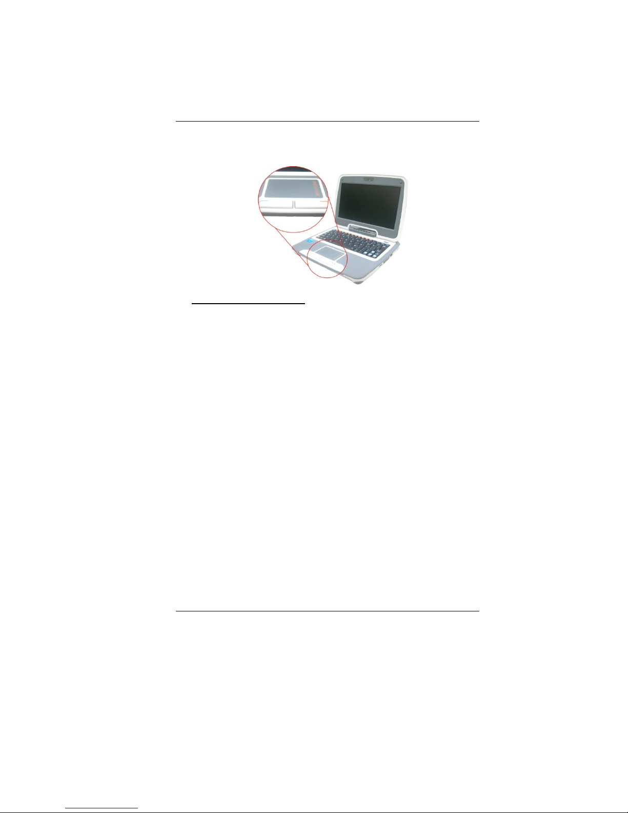
TThhee TToouucchh PPaadd
The touch pad is a rectangular electronic panel located just
below your keyboard. Move your finger on the touch pad
and the pointer (arrow) on the screen moves in the same
direction. Use the buttons below the touch pad as left and
right mouse buttons. A mouse is a small mobile manual
Page 35
27
device that controls movement of the cursor and selection
of functions on a computer display.
Touch Pad Precautions
The touch pad is a pressure sensitive device. Please take
note of the following precautions.
Make sure the touch pad does not come into contact
with dirt, liquids or grease.
Do not touch the touch pad if your fingers are dirty.
Do not rest heavy objects on the touch pad or the touch
pad buttons.
You can use the touch pad with Microsoft® Windows® as
well as non-Windows applications.
RReesseettttiinngg tthhee SSyysstteemm
After installing a software application package, you may be
prompted to reset the system to load the changed
operating environment.
To reset the system, or “reboot,” press the
[Ctrl]+[Alt]+[Delete] keys simultaneously. This is known as
“warm boot.” This key combination acts as “software”
reset switch when you encounter hardware or software
problems, which lock up the MPC TXTbook™ PC.
Should the computer lock up for some reason, press the
power button to power the MPC TXTbook™ PC
off.
Page 36
28
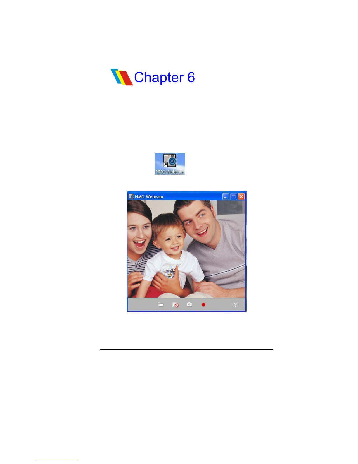
This application offers video conferencing capabilities to
work and communicate in real-time with one or more
participants through streaming video.
WWeebb CCaammeerraa AApppplliiccaattiioonn
Double-click the icon key to display the “NMG
Webcam” screen display. Your image will immediately
display on the small screen.
WWeebb CCaammeerraa AApppplliiccaattiioonn
Page 37
29
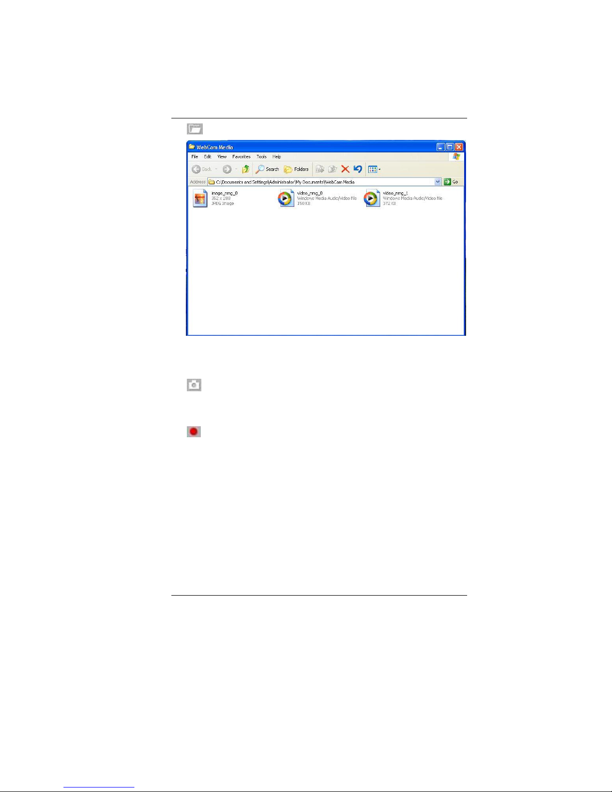
Open Folder
Click on this function to locate the files where you
captured image files or recorded video files.
Snapshot
Use this function to capture the image file of the other
party when you are on video conferencing.
Record
Use this function to start recording on the video files when
you are starting video conferencing.
Page 38

30
TThhee ttrroouubblleesshhoooottiinngg aaccttiivviittyy sshhoouulldd oonnllyy bbee
ppeerrffoorrmmeedd bbyy aann aadduulltt..
Your computer has been fully tested and complies with the
system specifications before shipping. However, incorrect
operations and/or mishandling may cause problems.
This chapter provides a reference for identifying and
correcting common hardware and software problems that
you may encounter.
When you encounter a problem, you should first try to go
through the recommendations in this chapter. Instead of
returning the computer and waiting for repair, you may
easily solve the problems by considering the following
scenarios and possible solutions. If the error continues,
contact your reseller for service information.
Before taking further actions, consider the following
suggestions:
Check to see if the problem persists when all the
external devices are removed.
Check to see if the power cord is properly plugged into
the wall outlet and to the computer.
Check to see the power indicator of the computer is on.
Check to see if your keyboard is operational by
pressing and holding any key.
Check for any incorrect or loose cable connections.
Make sure the latches on the connectors latch securely
onto the receptor end.
Be sure you have not performed an incorrect setting on
the hardware devices in the BIOS Setup utility. A faulty
setting may cause the system to malfunction. If you
are not sure of the changes you have made, try to
TTrroouubblleesshhoooottiinngg
Page 39

31
restore all the settings to factory defaults.
Be sure all the device drivers are installed properly.
For example, without the audio driver properly
installed, the speakers and microphone will not work.
If external devices such as USB camera, scanner or
printer do not function correctly when connected to
the system, it is usually the device’s own problem.
Consult the device’s manufacturer instructions first.
Some software programs, which have not gone through
rigorous coding and testing, may cause problems
during routine use. Consult the software vendor for
problem solving.
Be sure to go to BIOS SETUP and load DEFAULT SETTING
after BIOS re-flash.
AAuuddiioo PPrroobblleemmss
No speaker output
Software volume control is turned down in Operating
System’s Sound System or is muted. Double-click the
speaker icon on the lower right corner of the taskbar
to see if the speaker has been muted or turned down
all the way.
Most audio problems are software-related. If your
computer worked before, chances are software may
have been set incorrectly.
Sound cannot be recorded.
Double-click the speaker icon on the lower right corner
of the taskbar to see if the microphone has been
muted.
Click Options and select Properties.
Select Recording and click the OK button.
After clicking the OK button, the recording volume
control panel will appear.
Page 40

32
HHaarrdd DDiisskk PPrroobblleemmss
The hard disk drive does not work or is not recognizable:
If you had just performed a hard disk upgrade, make
sure the hard drive connector is not loose and the hard
disk drive is also correctly seated. Remove it and
reinsert it firmly and restart your PC. (Refer to Chapter
5 for details.)
The new HDD may need to be partitioned and
reformatted. O/S and drivers will need to be reinstalled as well.
Check the hard disk indicator LED. When you access a
file, the LED lamp should light up momentarily.
The new HDD may be defective or is not compatible.
If your computer has been subjected to static
electricity or physical shock, you may have damaged
the disk drive.
The hard drive is making abnormal whining noises.
You should back up your files as soon as possible.
Make sure the source of noise is indeed from the hard
drive and not the fan or other devices.
The hard disk drive has reached its capacity.
Archive files or programs that you no longer use by
moving them to an alternative storage medium (card
reader, etc.) or uninstall unused programs.
Many browsers store files in the hard drive as a cache
to speed up the performance. Check the operating
system’s Online Help for instructions on decreasing the
cache size or on removing temporary Internet files.
The hard disk takes longer to read a file.
Interrupt requests or problems with other hardware
devices may have occupied the CPU and therefore
slows down the system performance.
Page 41

33
DDiissppllaayy PPrroobblleemmss
The display panel is blank when the system is turned on.
Make sure the computer is not in the Standby or
Hibernate suspend modes. The display is turned off to
conserve energy in these modes. To “wake” the MPC
TXTbook from suspend mode, press the power button
and release.
The screen is difficult to read.
The display resolution should be set to at least
800x480 for optimal viewing.
The screen flickers.
It is normal if the display flickers a few times during
shutting down or powering up processes.
KKeeyybbooaarrdd aanndd TToouucchh PPaadd PPrroobblleemmss
The built-in touch pad performs erratically.
Make sure there is no excess perspiration or moisture
on your hands when using the touch pad. Keep the
surface of the touch pad clean and dry.
Do not rest your palm or wrist on the surface of the
touch pad while typing or using the touch pad.
The built-in keyboard accepts no input.
If you are connecting an external keyboard to the
system, the built-in keyboard may not work.
Try restarting the system.
The characters on the screen repeat while I type.
You may be holding the keys down too long while
you’re typing.
Keep the keyboard clean. Dust and dirt under the keys
could cause them to stick.
Page 42

34
MMeemmoorryy PPrroobblleemmss
The O/S issues an insufficient memory error message
during operation.
This is often a software or Operating System-related
problem. A program is draining the memory resources.
Close the application programs you’re not using and
restart the system.
NNeettwwoorrkk AAddaapptteerr // EEtthheerrnneett PPrroobblleemmss
The Ethernet adapter does not work.
Make sure the physical connections on both ends of the
cable are good.
The hub or concentrator may not be working properly.
Check to see if other workstations connected to the
same hub or concentrator are working.
The Ethernet adapter does not appear to operate in the
100Mbps transmission mode.
Make sure the hub you are using supports 100Mbps
operation.
Make sure that your RJ-45 cable meets the 100Base-TX
requirements.
Make sure the Ethernet cable is connected to the hub
socket that supports 100Base-TX mode. The hub may
have both 10Base-TX and 100Base-T sockets.
PPeerrffoorrmmaannccee PPrroobblleemmss
The computer becomes hot.
In a 35
o
C environment, certain areas of the computer’s
back case are expected to reach 50oC degrees.
Make sure the air vents are not blocked.
If the fan does not seem to be working at high
temperatures (50 degrees Celsius and up), contact the
service center.
Certain programs that are processor-intensive may
increase the computer temperature to a degree where
the computer automatically slows down its CPU clock
Page 43

35
to protect itself from heat damage.
The program appears stopped or runs very slowly.
Restart the computer.
This may be normal for the Operating System when it
is processing other CPU-intensive programs in the
background or when the system is accessing slowspeed devices such the floppy disk drive.
You may be running too many applications. Try to close
some applications or increase system memory for
higher performance.
The processor may have been overheated due to the
system’s inability to regulate its internal temperature.
Make sure the computer’s ventilation grills are not
blocked.
UUSSBB22..00 PPrroobblleemmss
The USB device does not work.
Make sure the cable is fully connected.
Make sure you have installed the necessary device
drivers.
Contact the device vendor for additional support.
Page 44
36
The Setup Utility is a hardware configuration program built
into your computer’s BIOS (Basic Input/Output System). It
runs and maintains a variety of hardware functions. It is
menu-driven software, which allows you to easily configure
and change the settings.
The BIOS contains Manufacturer’s default settings for the
computer’s standard operations. However, there are
occasions when you may be required to modify the default
settings in the BIOS.
The BIOS allows you to set up passwords to limit access to
users. This is an important feature because a great deal of
vital information is carried within the computer nowadays.
Unauthorized access can be prevented. Later in this
chapter, you will learn how to use this security feature.
EEnntteerriinngg tthhee BBIIOOSS SSeettuupp SSccrreeeenn
First turn on the power. When the BIOS performs the POST
(Power-On Self Test), press DEL key quickly to activate the
Setup Utility.
You may need to press DEL key fairly
quickly. Once the system begins to load operating
system, you may have to retry by cycle-power on again.
LLeeaavviinngg tthhee BBIIOOSS SSeettuupp SSccrreeeenn
When you have finished modifying the BIOS settings, exit
the BIOS. It takes a few seconds to record changes in the
CMOS.
BBIIOOSS SSeettuupp aanndd SSeeccuurriittyy
FFeeaattuurree
Page 45
37
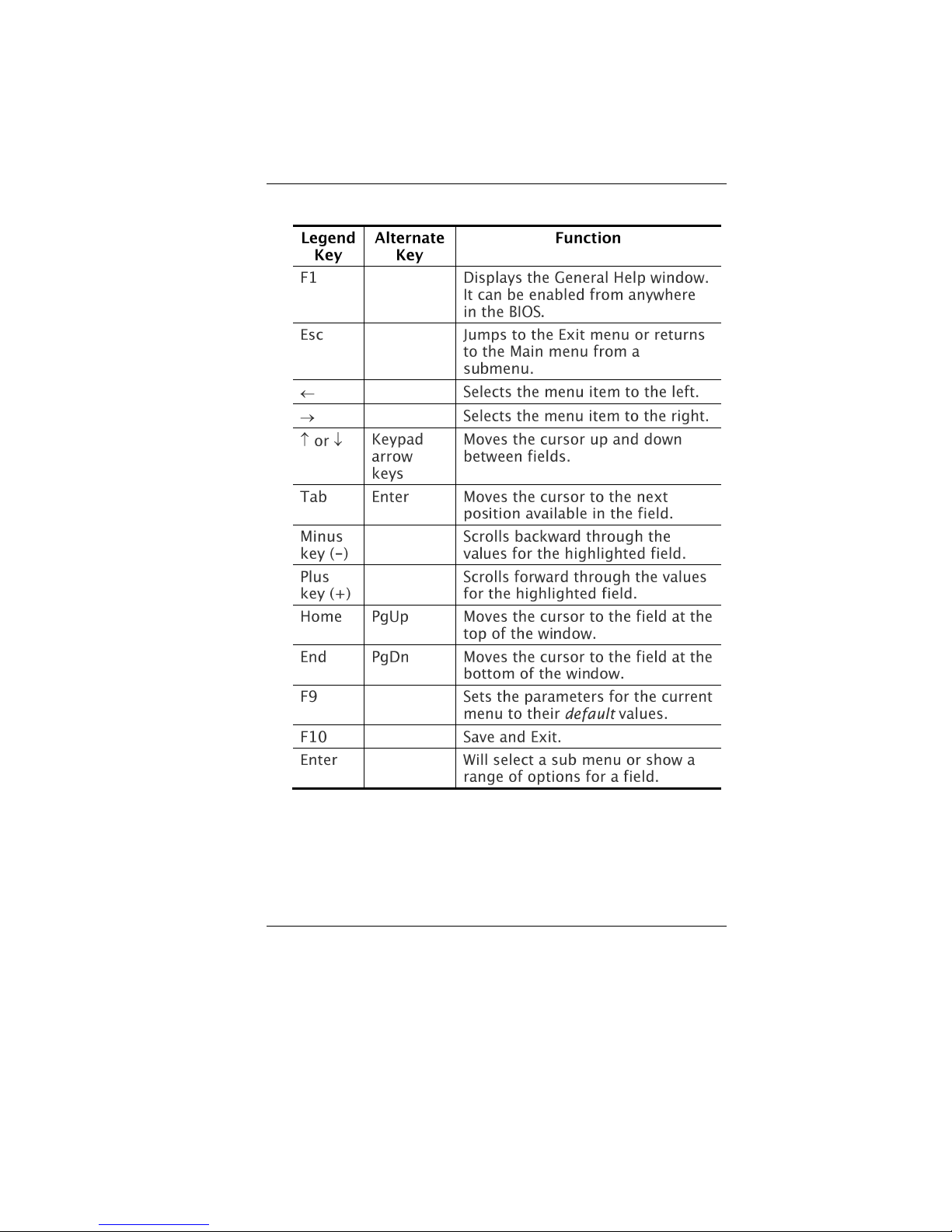
BBIIOOSS AAccttiioonn KKeeyyss
MMooddiiffyyiinngg tthhee BBIIOOSS SSeettttiinnggss
The BIOS setup main menu is subdivided into sub-menus.
Each menu item is described in this section.
Page 46
38
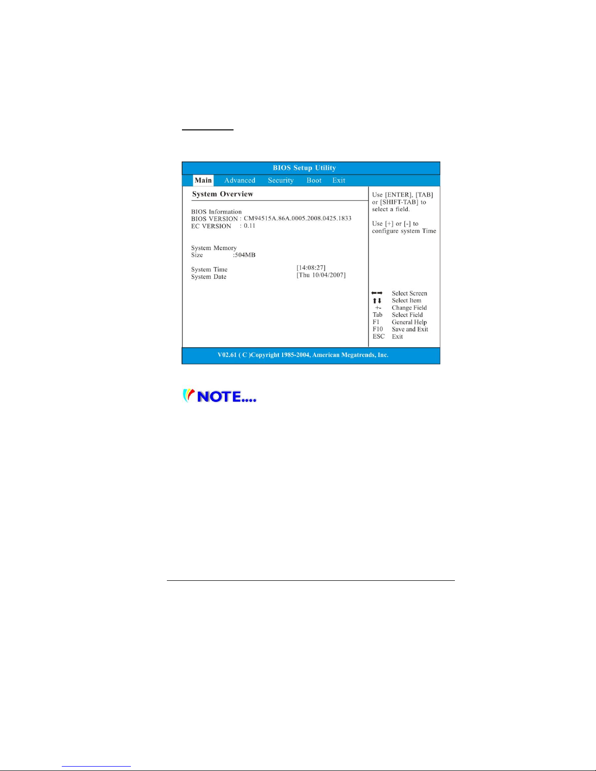
Main Setup
Under this menu, you may change time/date and view basic
processor and system memory information.
Due to various configurations on this
model, your system may show different information.
System Time: Type in the current time, in HH:MM:SS
format.
System Date: Type in the current date, in MM/DD/YY
format.
Page 47
39
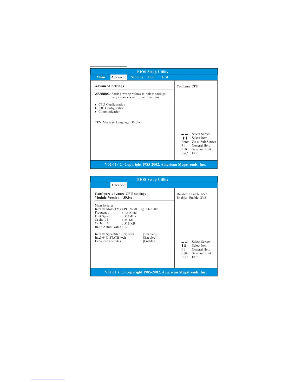
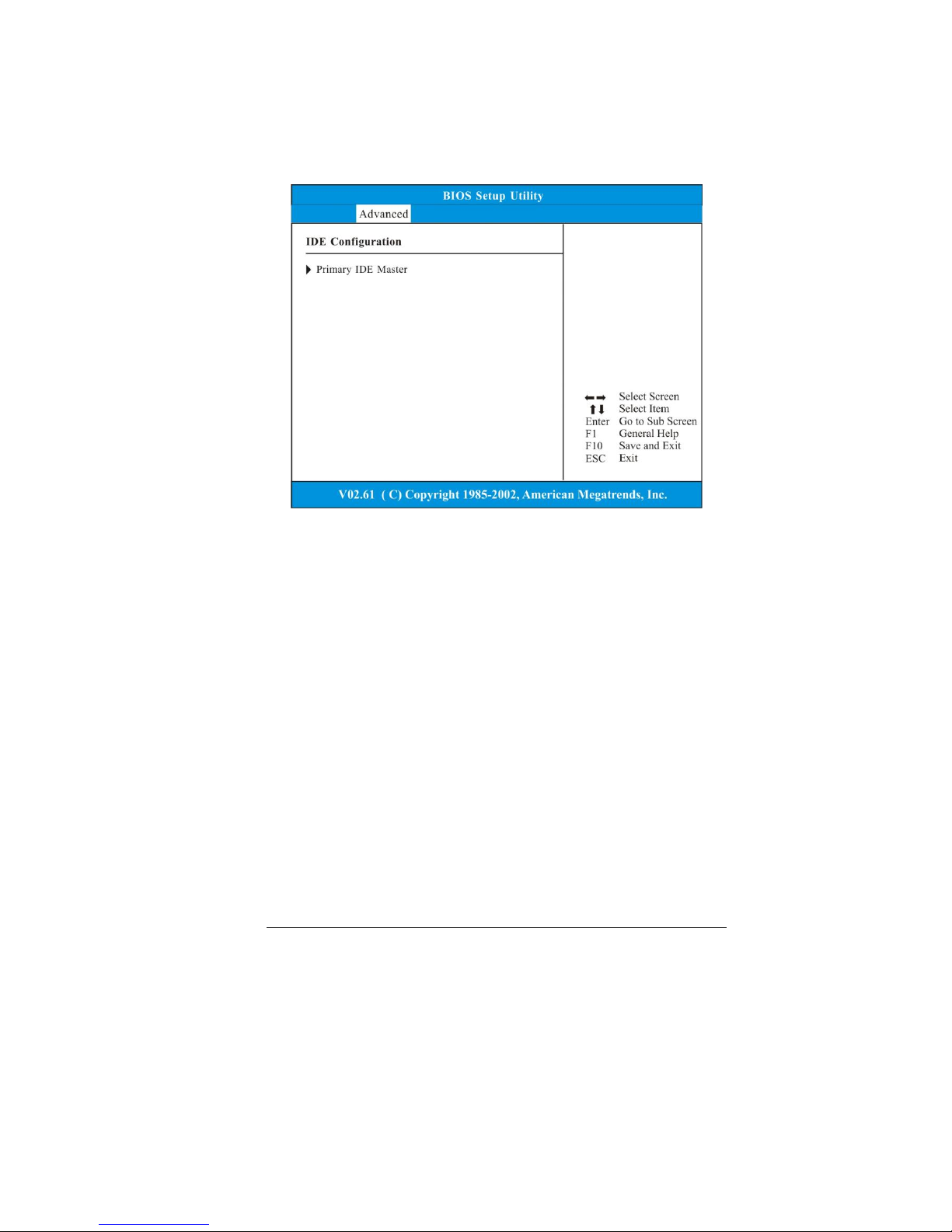
Advanced Setup
Page 48
40
Page 49
41
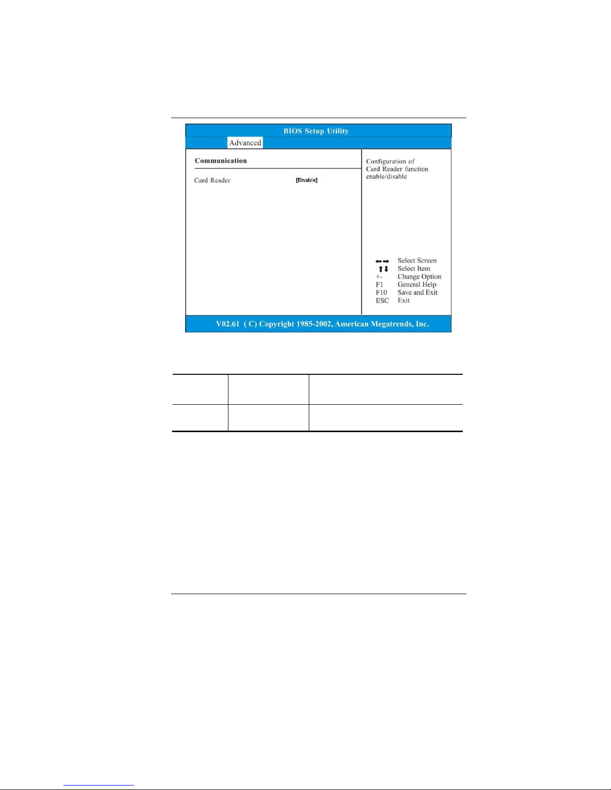
Communication: See Above.
Item
Selections /
Sub-menu
Description
Card
Reader
Enable/Disable
Enable or disable the Card
Reader function.
Page 50
42
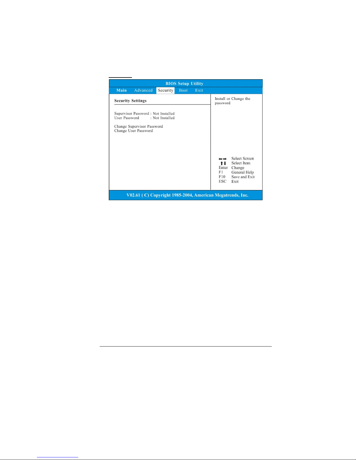
Security
Supervisor Password: Install or Change the Password.
User Password: Install or Change the Password.
UUssiinngg PPaasssswwoorrdd PPrrootteeccttiioonn
Two Levels of Password Protection are available. The BIOS
provides both a Supervisor and a User password. If you try
to activate both passwords, the Supervisor password must
be set first.
The passwords activate two different levels of protection:
1. System always asks for password every time it is
powered on.
2. System asks for password only when you attempt to
enter BIOS utility.
The passwords are encrypted and stored in NVRAM. Make
sure you write them down or memorize them. If you loose
the passwords, the computer may need to be sent back to
the factory or to an authorized service dealer to reset the
passwords.
Page 51
43
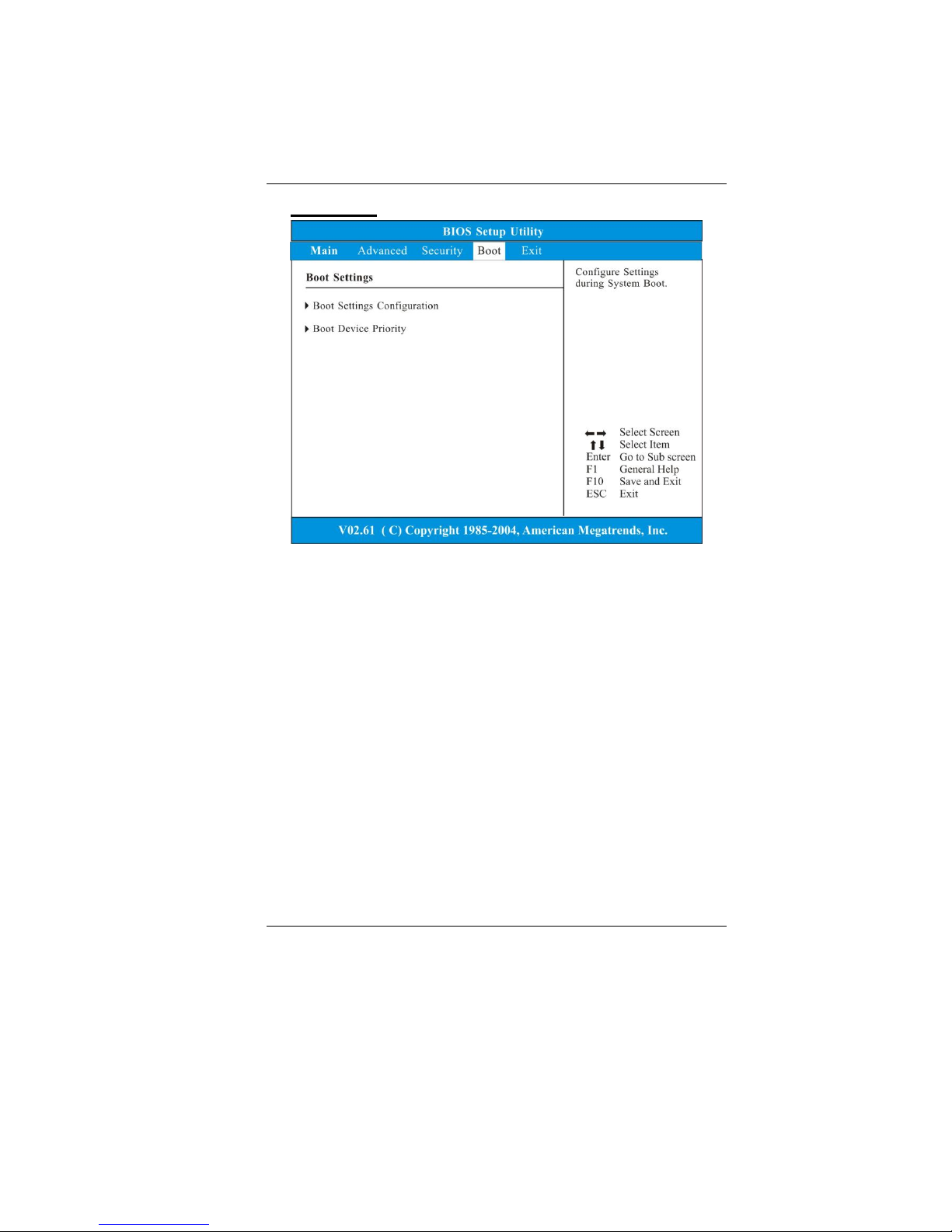
Boot Setup
Page 52
44
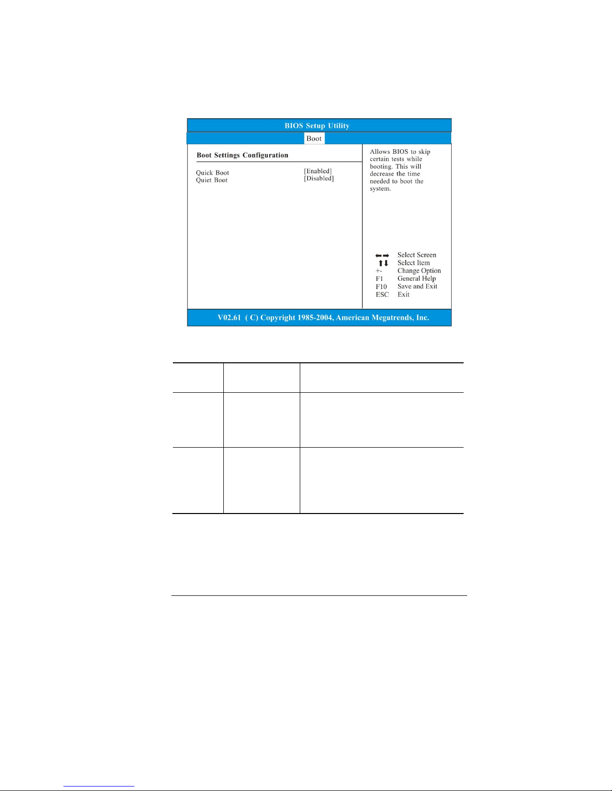
Boot Settings Configuration: See Above.
Item
Selections /
Sub-menu
Description
Quick Boot
Disabled
Enabled
[Enabled]: The system skips certain
tests while booting. This shortens the
boot-up time.
[Disabled]: The system performs full
tests while booting.
Quiet Boot
Disabled
Enabled
When Enabled, the system will
display OEM logo instead of the POST
messages.
When Disabled, the system will
display POST messages (i.e. devices
information.)
Page 53
45
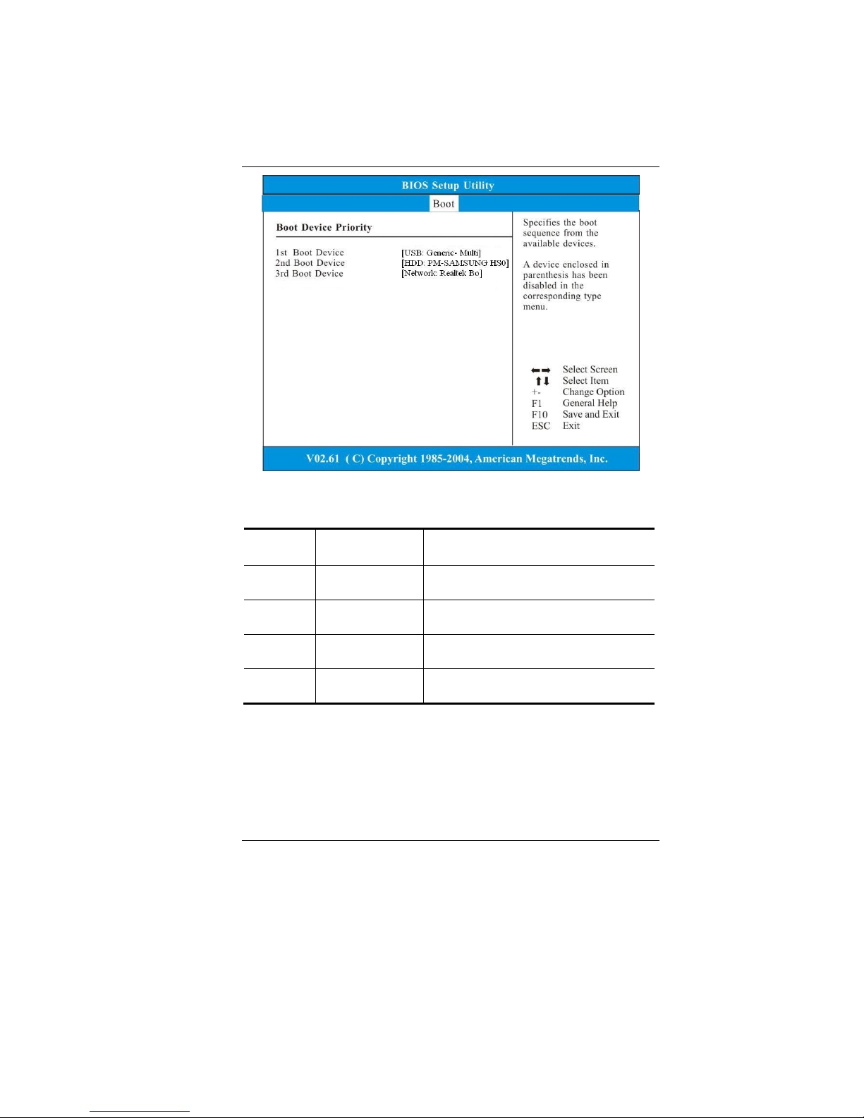
Boot Device Priority: See Above.
Item
Selections/Sub-
menu
Description
1st Boot
Device
USB: Sandisk
uSSD 5
Set the type of device for the third
drive BIOS attempts to boot from.
2nd Boot
Device
USB: USB
Hotplug FD
Set the type of device for the third
drive BIOS attempts to boot from.
3rd Boot
Device
Network: Realtek
Boot Agent
Set the type of device for the third
drive BIOS attempts to boot from.
4th Boot
Device
USB; GenericMulti
Set the type of device for the third
drive BIOS attempts to boot from.
Page 54
46
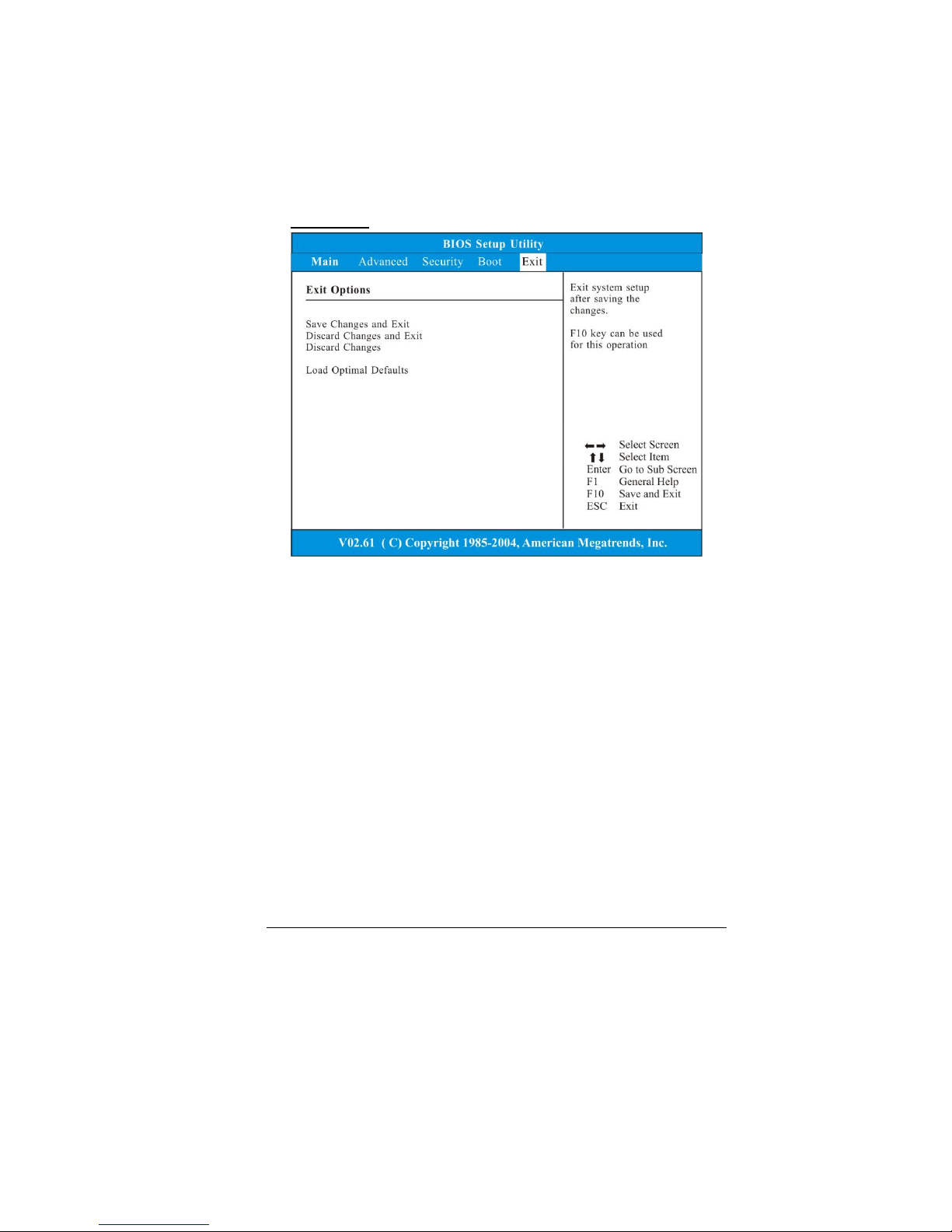
Exit Setup
Save Changes and Exit: After you have completed the
BIOS settings, select this item to save all settings, exit
BIOS Setup utility, and reboot. New system settings will
take effect on next power-up. F10 key can be used for
this operation.
Discard Changes and Exit: Discards changes done so far
to any of the setup questions and exit.
Discard Changes: Discards changes done so far to any
of the setup questions.
Load Optimal Defaults: Load Optimal Default value for
all the setup questions. F9 key can be used for this
operation.
Page 55

47
SSppeecciiffiiccaattiioonn
CPU
Intel® ATOM N270 processor 1.6GHz
512K SLB73 FSB@533MHZ
Memory
DDR2 400/533 SO-DIMM DRAM module
256, 512 MB and 1GB
SO DIMM 200-pin socket * 1
Core Logic
Intel® 945GSE
ICH7-M
Audio Codec
Realtek ALC662
Card reader (2 in 1)
Support SD/MMC Memory Card.
USB 2.0 interface
LAN Controller
Supports 10 and 100 Mb/sec. Full and half Duplex
operation
Wireless LAN
Mini-card form factor
Wi-Fi 802.11 b/g with open mesh support
Single antenna
Keyboard
Integrated QWERTY keyboard W/ Hot key 77 KEY
K/B
Page 56

48
Pointing Device
PS/2 touch pad with left and right click button
and scrolling bar
Camera
USB2.0 interface
30fps @ 640x480, 0.3M
Driver/AP support Windows XP
Storage
Nand Flash
1G/2G/4G/8G Nand Flash
USB interface 8G USSD 5000, Intel 8G PATA Flash
1.8” HDD
Support PATA HDD, 4200rpm, H: 5mm
Capacity: 30GB, 40GB and 60GB
LCD
Color LCD TFT, LED Backlight
800x480; 1024X600, LVDS interface
7" with 800X480 resolution;
8.9" with 1024x600 resolution
Battery Pack
4 cell (2S2P) Li-ion battery pack
7.4V/4400mAH (2S2P), 3.7V/2200mAH/ Samsung
cell
7.2V/4400mAH (2S2P), 3.6V/2200mAH/ LG cell
6 cell (2S3P) Li-ion battery pack
7.4V /6600mAH (2S3P), 3.7V/2200mAH/Samsung
cell
7.2V /6600mAH (2S3P), 3.6V/2200mAH/LG cell
AC-Adapter
Automatics Voltage adjustment between 100 and
240VAC 50/60Hz 40Watts
20V/40W
Page 57

49
Supports 2pin and 3 pin power cord
BIOS
Support PnP & ACPI 2.0
Support external USB flash memory card boot up.
Physical Outline
Dimension: 241mm W x 198.5mm H x 40.5mm D
(Without PU bag and without handle)
Weight: (Without PU bag and without handle)
7" W LCD/SSD/4 cell battery pack: 1.29kg
8.9" W LCD/HDD/ 4 cell battery pack: 1.52kg
EMC
CE
FCC
CCC
RF
FCC/R&TTE
Safety
UL/CB/ETL
CCC
WEEE
RoHS (Restriction of Hazardous Substances, EU
directive 2002/95/EC + amendments)
ENERGY STAR 4.0
SSeerrvviiccee aanndd SSuuppppoorrtt
1-(877) 485-1464
http://support.mpccorp.com/index.html
 Loading...