

Page 1
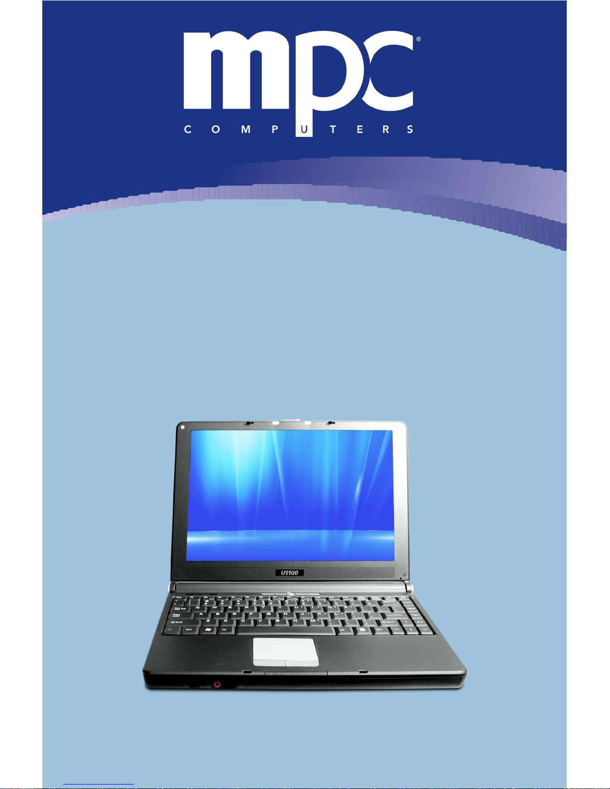
TransPort
®
U1100
Technical Reference Manual
Page 2
2
Preface
Table of Contents
Copyright Information................................................................................7
Trademark Notice..................................................................................8
Limitation of Liability..............................................................................8
Notices...................................................................................................9
Life Support and Nuclear Facilities........................................................9
Energy Star® Notice ................................................................................10
Network Compatibility..........................................................................11
Welcome .................................................................................................12
MPC Resources......................................................................................13
Easy Setup Guide................................................................................13
Further Reading...................................................................................13
For More Information...........................................................................13
Manual Comments ..............................................................................13
Service and Support Tools..................................................................14
Manual Conventions ...............................................................................16
Special Text.........................................................................................16
Optical Device Naming Convention.....................................................17
Touchpad Conventions........................................................................17
Windows Conventions.........................................................................18
Software User Documentation.............................................................18
Printing the Manual.................................................................................19
Page 3

3
Preface
Manual Updates......................................................................................20
TransPort® U1100 Safety and Care........................................................21
Operating Environment........................................................................21
Temperature Concerns....................................................................21
Humidity, Rain, and Moisture...........................................................22
Other Environmental Concerns...........................................................22
Magnetic Fields................................................................................23
Direct Sunlight and Extreme Temperatures.....................................23
TransPort® U1100 Package....................................................................24
Using Your TransPort® U1100................................................................25
Caution on Using Modem ................................................................26
Turning On and Off .................................................................................27
Power On Information..........................................................................27
Powering Off Information.....................................................................28
Standby or Hibernation Mode..............................................................30
Specifications..........................................................................................32
TransPort® U1100 Features....................................................................35
Top Open View....................................................................................35
Front View............................................................................................37
Right-Side View...................................................................................39
Left-Side View .....................................................................................40
Rear View............................................................................................41
Bottom View ........................................................................................42
Power Management................................................................................44
AC Adapter..........................................................................................44
Connecting the AC Power...................................................................44
Page 4

4
Preface
Disconnecting the AC Power...............................................................45
Battery Pack ........................................................................................45
Releasing the Battery Pack.................................................................46
Replacing the Battery Pack.................................................................47
Using the Battery Pack........................................................................48
Battery Safety Tips...........................................................................48
Conserving Battery Power...............................................................48
Charging the Battery Pack...............................................................49
Using the Main System Battery Safely................................................50
Your Computer’s CMOS Battery Care ................................................51
Keyboard and Touchpad.........................................................................53
Keyboard .............................................................................................53
Typewriter Keys...............................................................................54
Cursor Keys.....................................................................................55
Numeric Keys...................................................................................57
Function Keys..................................................................................58
Touchpad.............................................................................................60
Using the Touchpad.........................................................................61
Windows Vista Business.........................................................................64
Desktop................................................................................................64
Start Menu...........................................................................................65
Window................................................................................................66
Tour ....................................................................................................68
Peripheral Devices..................................................................................69
Connecting the Peripheral Devices.....................................................72
Connecting the Mouse.....................................................................72
Page 5

5
Preface
Connecting the Keyboard................................................................73
Connecting the WebCam.................................................................73
Connecting the Printer.....................................................................74
Connecting the External Monitor or TV............................................74
Connecting the IEEE 1394 Devices.................................................75
Connecting the Communication Devices ............................................76
Using the LAN..................................................................................76
Using the Modem.............................................................................76
Express PC Card Installation..................................................................77
Installing the Express Card..................................................................77
Removing the Express Card................................................................77
Safely Remove Hardware.......................................................................78
BIOS Setup .............................................................................................79
When to Use BIOS Setup?..................................................................79
How to Run Bios Setup? .....................................................................79
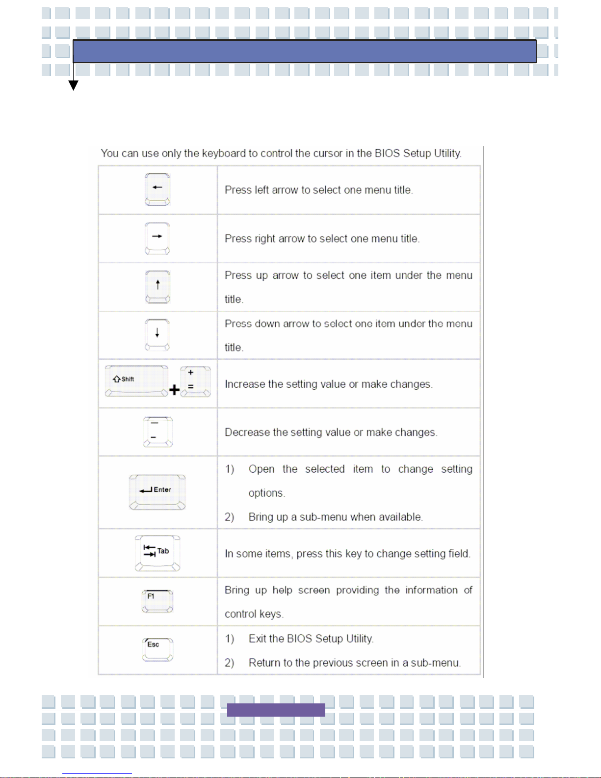
Control Keys........................................................................................80
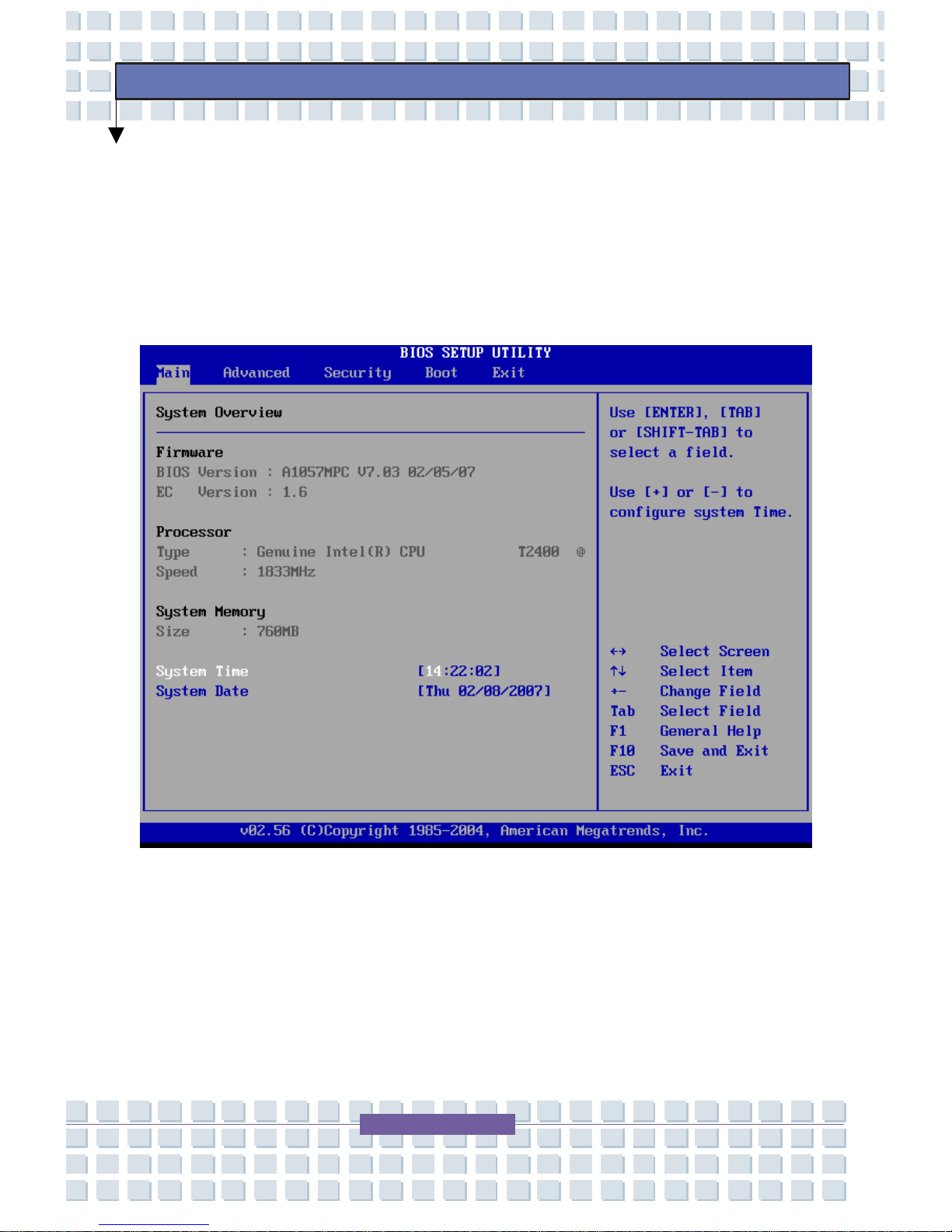
BIOS Setup Menu................................................................................81
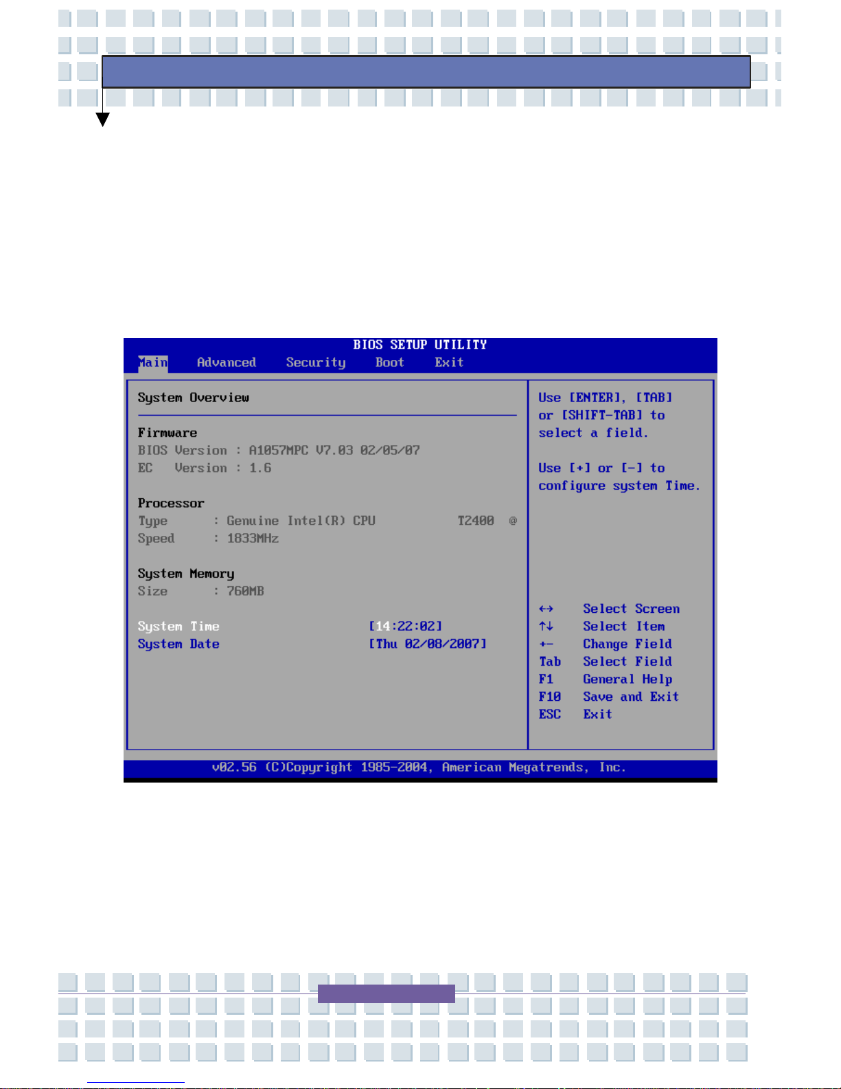
Main Menu .......................................................................................82
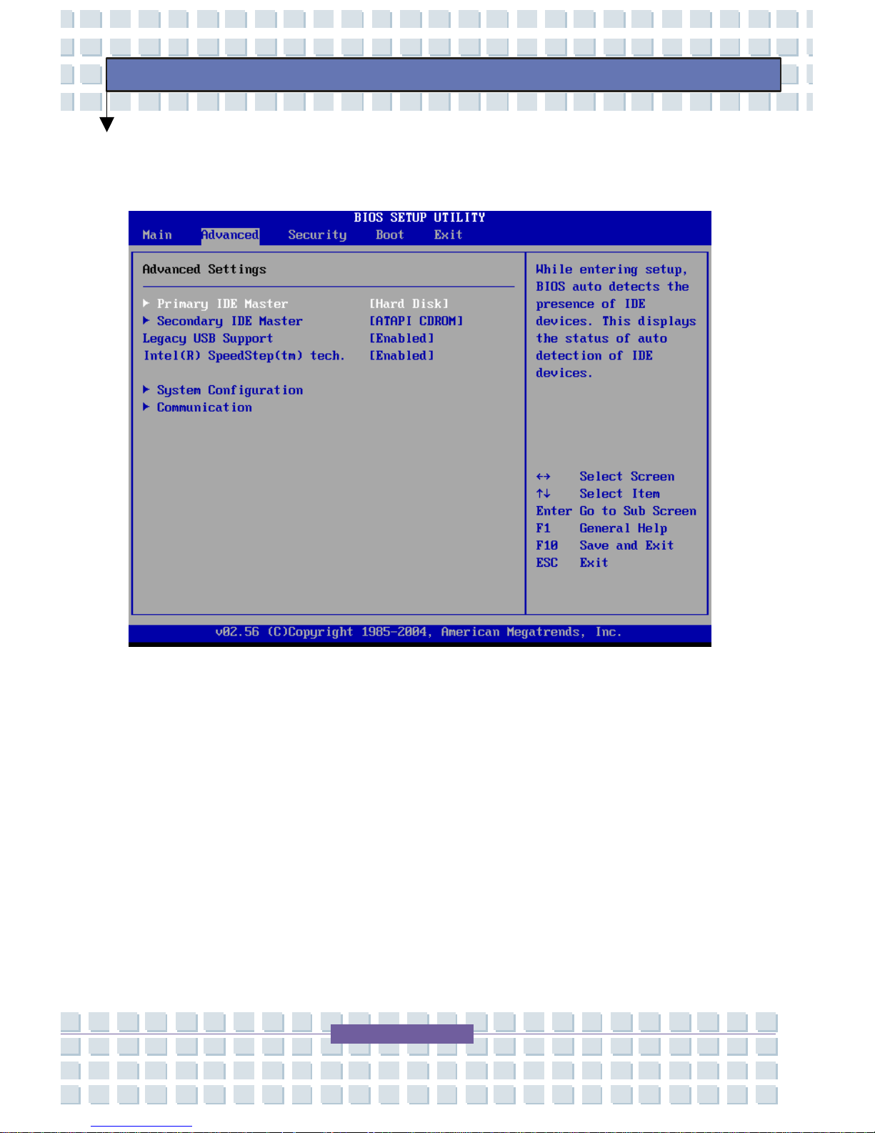
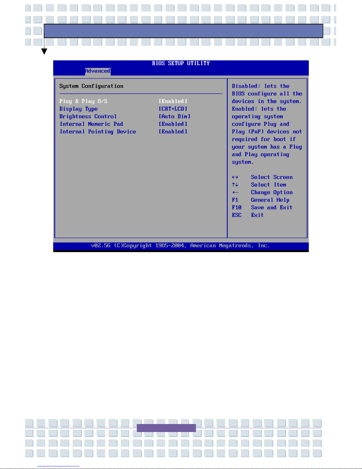
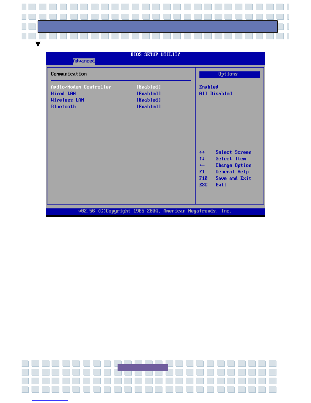
Advanced Menu...................................................................................84
Advanced Settings...........................................................................86
Security Menu......................................................................................88
Security Settings..............................................................................88
Boot Menu ...........................................................................................90
Exit Menu.............................................................................................91
The Computer’s CMOS Battery Care..................................................92
Regulatory Notices..................................................................................94
Page 6
6
Preface
FCC-B Radio Frequency Interference Statement............................94
Wireless LAN Module Statement.....................................................95
Product Specifications .....................................................................97
Radio Specifications ........................................................................98
Electromagnetic Compatibility .........................................................99
FCC Radiation Exposure Statement................................................99
FCC Part 68 Statement..................................................................100
CTR21 Statement..........................................................................102
Canadian Radio Interference Regulations.....................................102
Class 1 Laser Product....................................................................103
Power Cord Requirement..............................................................104
Optical Disk Drive Notice...............................................................105
Country-Specific Power Cord Set Requirements ..........................105
Country-Specific Power Cord Set Requirements ..........................106
Safety Approval..............................................................................107
Safety Guideline for Using Lithium Battery........................................108
WEEE Statement .........................................................................109
Page 7

7
Preface
Copyright Information
Copyright 2006-2007 MPC Computers, LLC. All rights reserved. The
information in this document is subject to change without prior notice in
order to improve reliability, design, and function and does not represent a
commitment on the part of the manufacturer. In no event will the
manufacturer or seller of an MPC product be liable for direct, indirect,
special, incidental, or consequential damages arising out of the use or
inability to use the product or documentation, even if advised of the
possibility of such damages. Except as stated in the applicable MPC
Computers, LLC limited warranty, MPC and its affiliates, by this manual,
make no other express warranties. THE IMPLIED WARRANTY OF
MERCHANTABILITY AND THE IMPLIED WARRANTY OF FITNESS
FOR A PARTICULAR PURPOSE ARE HEREBY DISCLAIMED. IF
THESE LIMITATIONS DO NOT APPLY TO YOU, THEN ALL IMPLIED
WARRANTIES AND CONDITIONS OF MERCHANTABILITY AND
FITNESS FOR A PARTICULAR PURPOSE ARE LIMITED IN TIME TO
THE TERM OF THE LIMITED WARRANTY PERIOD REFLECTED ON
YOUR PACKING SLIP OR INVOICE. NO WARRANTIES, WHETHER
EXPRESS OR IMPLIED, WILL APPLY AFTER THE LIMITED
WARRANTY PERIOD HAS EXPIRED.
Page 8

8
Preface
This document contains proprietary information that is protected by
copyright. All rights are reserved. No part of this document may be
photocopied, reproduced, or translated to another language withou t the
prior written consent of:
MPC Computers, LLC
906 E. Karcher Road
Nampa, Idaho 83687
Trademark Notice
Windows, Windows
®
98/ME, Windows 2000, MS-DOS, Windows Vista
Business, and Microsoft are registered trademarks of Microsoft
Corporation. AMI
®
is a registered trademark of American Megatrends,
Inc. Pentium and MMX are trademarks or registered trademarks of Intel
Corporation. PCMCIA and CardBus are registered trademarks of the
Personal Notebook Memory Card International Association. Other
product names mentioned herein are used for identification purposes
only and may be trademarks and/or registered trademarks of their
respective companies.
Limitation of Liability
While reasonable efforts have been made to ensure the accuracy of this
manual, the manufacturer and seller assume no liability resulting from
errors or omissions in this manual or from the use of the information
contained herein.
Page 9

9
Preface
Notices
No part of this publication may be reproduced, stored in a retrieval
system, or transmitted, in any form or by any means (mechanical
photocopying, recording or otherwise) without the prior written permission
of the manufacturer.
The information within this manual is subject to change without notice.
The manufacturer shall not be held liable for technical or editorial errors
or omissions contained herein; nor for incidental or co nsequential
damages resulting from the furnishing, performance, or use of this
material.
Life Support and Nuclear Facilities
Products sold by MPC are not authorized for use as critical components
in medical devices or systems or in nuclear facilities without the e xpress
written approval of the Chief Executive Officer of MPC.
EMA001107-01, MLW, 2/12/2007
Page 10

10
Preface
Energy Star® Notice
The need to reduce the pollution associated with energy production is
imperative. The Environmental Protection Agency (EPA) developed the
Energy Star program to combat the problem of energy waste. This
cooperative effort between government and private industry is designed
to decrease the power consumed by computing equipment as well as a
wide range of other products, homes, and buildings. Energy Star
specifications require that both the TransPort
®
U1100 system and
monitor enter a low-power "sleep" mode after a period of inactivity.
MPC is proud to be an official Energy Star partner. This voluntary
partnership signifies that most MPC Computer systems meet the
stringent Energy Star guidelines. You will see the savings achieved
through Energy Star labeled equipment in the form of lower power bills—
without sacrificing performance or paying more for your system.
We join Energy Star in its commitment to reduce unnecessary pollution.
Although certain configurations and system options may prevent your
system from meeting Energy Star guidelines, your system still has built-in
energy saving features. Check with your MPC sales representative to
see if your configuration meets the Energy Star guidelines.
Page 11

11
Preface
Refer to the Power Management section in this manual for more
information on modifying your Power Management settings or default
times.
Network Compatibility
The power-saving functions may vary among different network operating
systems. If the system is to be permanently connected to a network, we
recommend the TransPort
®
U1100’s "wake up" function be tested before
relying on this mode.
Page 12

12
Preface
Welcome
Congratulations on the purchase of your MPC TransPort® U1100.
Whether you are a new or an experienced TransPort user, this Technical
Reference Manual can help you get the most from your TransPort
®
U1100.
The following sections in this chapter contain more information about
your TransPort
®
U1100 and this manual:
MPC Resources
System Information
Manual Conventions
Printing the Manual
Manual Updates
Page 13

13
Preface
MPC Resources
MPC provides several resources to assist you with using your new
TransPort
®
U1100.
Easy Setup Guide
For quick step-by-step setup instructions, refer to the Easy Setup Guide.
Further Reading
It is recommended that you read all documentation, in addition to this
manual, related to any software or hardware supplied with your
TransPort
®
U1100.
For More Information
For the latest information about your TransPort
®
U1100 and about MPC
services, please visit the MPC Web site at
www.mpccorp.com.
Manual Comments
If you would like to comment on the manuals, please contact us at
Page 14
14
Preface
Service and Support Tools
MPC provides many support tools to make using your TransPort® U1100
easier. These support tools can be found by clicking on one of the links
below.
Main Support Site http://support.mpccorp.com
Knowledge Base http://primus.mpccorp.com/mknowledge/
Contacting Support
Customer Service Phone Number:
(877) 894-5693
Technical Support Phone Number:
(800) 877-8856
(888) FIX-MYPC (888) 349-6972
The following tools are available to MPC customers:
a searchable Knowledge Base to find answers to your questions
downloadable drivers and utilities
updated versions of this manual
Contacting Technical Support
Technical Support is available 24 hours a day, 7 days a week.
Page 15
15
Preface
System Information
Please record your TransPort
®
U1100's operating information on the
"System Information" section of the
Easy Setup Guide. If you require
technical support in the future, the following information will help an MPC
support technician locate the specifications for your TransPort
®
U1100
and aid in returning it to normal operation.
Model and Serial Number Information
Model Name:
TransPort® U1100
Manual Number:
EMA001107-01
Page 16

16
Preface
Manual Conventions
The following conventions are used throughout this manual.
Note: Important information concerning the
operation of your notebook
Warning: Failure to follow directions will result
in loss of data or damage to equipment and/or
could result in physical harm. Failure to heed
these warnings could negate the user warranty.
Caution: Failure to follow directions could
result in loss of data or damage to
equipment.
Special Text
The text in this guide is formatted to highlight unique information or
instructions. Review the following examples of special text used
throughout this manual:
Screen (window) names, functions, or anything that appears on
the screen is formatted in bold. For example: Click OK, the
Standards screen, and the Edit menu.
Page 17

17
Preface
Brackets indicate keyboard strokes. For example: Press [Enter],
use the [Alt] key. When keys should be held down
simultaneously, they are separated by the + sign. For example:
Press [Ctrl+Alt+Delete]. When keys should be pre ssed
sequentially, they will be in individual brackets without the + sign.
For example: Press [1][Enter]. The [1] key should be pressed
first, and then the [Enter] key should be pressed.
Screen messages are indicated by quotes. For example: The
message "Enter your username and password" will appear.
Anything that you need to type will appear in italics. For example:
Enter the word password.
Optical Device Naming Convention
In many installation programs you will have to get a program from the
optical device. The program installation sequence as sumes that the
optical drive is drive d:\, however this is not always the case. The name
of the optical drive is the letter following the letter assigned to your last
HDD. For instance, if you have one HDD with two partitions, the HDD is
drives C: and D: and the optical drive is then drive E.
Touchpad Conventions
You may be asked to click or double-click on items on the display screen.
As a general note the touchpad actions are similar to a wheel mou se,
any differences are explained fully.
Page 18

18
Preface
The object that needs to be clicked upon will be displayed in Bold text
such as the Start button.
Windows Conventions
Almost all Windows
®
programs will display the name of a button or icon
if you place the touchpad pointer on the item you want information about.
Software User Documentation
Your notebook is shipped from the factory with several software
programs installed. The software may include its own online
documentation. Refer to the documentation or the Help options in the
software for more information.
Page 19
19
Preface
Printing the Manual
To print the manual, complete the following steps:
1. Click on “File” on the menu bar.
2. From the dropdown, click on “Print”.
3. When the Print dialog box appears, make the appropriate
selections, click OK, and print the manual.
Note: The Print dialog box may take a few seconds
to appear. Also, the Print dialog box may minimize
to the taskbar, so check the taskbar if the dialog
box doesn't appear.
Page 20

20
Preface
Manual Updates
Periodically, updates are made to our manuals. Use the following
instructions for finding the most current Technical Reference Manu al for
your system. Please note that not all of the manual updates will be
applicable to your system.
1. Go to the MPC Support Web site at
http://support.mpccorp.com.
2. Click on the Platforms link.
3. Select the Components link.
4. Click on the Manuals link.
Find the TransPort
®
U1100 Technical Reference Manual link and select
the EMA001107-XX link.
If the manual has been updated, the -XX number will be greater than -00,
such as -01, -02, and –03. If you find a manual update, download the
manual by clicking on the link and following the on-screen instructions.
Page 21
21
Preface
TransPort® U1100 Safety and Care
Operating Environment
Temperature Concerns
Keep this equipment away from humidity, direct sunlight, high room
temperatures, and away from other heat sources (such as lamps and
heating vents). The system specifications ensure the TransPort
®
U1100
will not be left in an unconditioned environment with a storage
temperature of 60
O
C (140OF) or above, which may damage the
equipment. Make sure the fan vent on the right side of your TransPort
®
U1100 is not blocked when you use your TransPort
®
U1100.
Caution: The TransPort® U1100's Liquid Crystal
Display (LCD) screen may be damaged by
exposure to intense sunlight, which builds up
excessive heat inside the displa
y
enclosure. Only
exposure to indirect or subdued sunlight is
recommended.
While your TransPort
®
U1100 will generally run better in cooler
environments, there are TransPort
®
U1100 components that are
adversely affected by cold temperatures. Exposing the TransPort
®
U1100
Page 22
22
Preface
to cold temperatures can produce condensation that can damage
individual components or destroy your system.
Humidity, Rain, and Moisture
Do not use your TransPort
®
U1100 in harsh conditions or near
water. Never spill liquid of any kind on the TransPort
®
U1100.
Warning: Never expose the TransPort® U1100
to moisture. Moisture exposure can lead to an
electrical shock or fire hazard. Operating the
TransPort
®
U1100 in areas with high humidity
can damage system components.
Avoid exposing your TransPort® U1100 to sudden changes in
temperature or humidity. Do not place yo ur TransPort
®
U1100 near
or over a radiator or heat register or in a built-in enclosure, unless
proper ventilation is provided.
Do not expose the TransPort
®
U1100 to rain or moisture.
Other Environmental Concerns
High levels of dust, dirt, or smoke can also damage your T ransPort
®
U1100. Place the TransPort
®
U1100 in an area with good ventilation.
Periodically check the TransPort
®
U1100 's case, side, and bottom to
ensure that dust or dirt is not accumulating on the ventilation portholes.
Page 23

23
Preface
Magnetic Fields
Place the TransPort® U1100 away from electromagnetic or radio
frequency interference (for example, television/stereo sets, copying
machine, and air conditioners.
Direct Sunlight and Extreme Temperatures
Avoid using or storing the TransPort® U1100 in extremely hot or cold
areas such as a car on a hot day. Keep the TransPort
®
U1100 away from
heaters and out of direct sunlight. Exposure to excessive heat may
damage TransPort
®
U1100 components.
If you have left your TransPort
®
U1100 in a hot place, let it cool down
slowly to room temperature (with the LCD panel open before using it.
Should your TransPort
®
U1100 be exposed to excessively cold
temperatures, please allow it to warm up to room temperature before
turning it on.
Do not place the TransPort
®
U1100 near fire or other heat sources.
Page 24

24
Preface
TransPort® U1100 Package
After you have carefully unpacked your TransPort® U1100, verify that you
have all of the items listed below. For a pre-configured model, you should
have the following items:
MPC TransPort® U1100
Accessories:
AC Adapter with AC power cord
MPC TransPort
®
U1100 Driver CD
Phone/Modem (RJ-11) telephone card
LAN (RJ-45) networking cable
Lithium ion battery (pre-installed)
Applicable Operating System Recovery CD
Easy Setup Guide
Product documentation (located on the Tr ansPort
®
U1100 Driver
CD and on the Windows
®
Desktop)
Warranty information
Appropriate application software (Software is installed at the
factory. You do not need to install any software unless your system
or documentation prompts you to do so.)
Inspect all of the items. If any item is damaged or missing, notify MPC
immediately. Keep the shipping carton and packing materials in case you
need to ship or store the TransPort
®
U1100 in the future.
Page 25

25
Preface
Using Your TransPort® U1100
Use only approved AC adapters, auto adapters, batteries, memory
modules, and other options. The TransPort
®
U1100 requires a 65W AC
adapter. An AC adapter with lower wattage will not power the system.
If you are using the TransPort
®
U1100 with the AC adapter, do not allow
anything to rest on the power cord.
Do not use the AC adapter or battery if the shell is cracked or damaged.
The TransPort
®
U1100 can be powered by an internal battery pack or by
an external AC power source, which is supplied with the TransPort
®
U1100. Using a different kind of battery pack or AC power source in your
TransPort
®
U1100 may create an explosion or fire hazard.
The TransPort
®
U1100 is equipped with a 3-wire type plug. If you are
unable to insert the plug into the outlet, contact your electrician to replace
your obsolete outlet.
If an extension cord is used with TransPort
®
U1100, the total amperage
ratings on the products plugged into the extension cord cannot exceed
the extension cord amperage rating. Also, the total of all products
plugged into the wall outlet should not exceed 15 amperage.
Page 26

26
Preface
Your TransPort® U1100 contains electrical filters, fuses, protections, and
a built-in surge protector. However, we strongly recommend using a highquality, external surge protector. An external surge protector looks like an
extension cord with several grounded outlets. It will help shield your
TransPort
®
U1100 from lightning strikes, surges, shorts, and other
electrical hazards. We also recommend plugging your phone line into a
surge protector.
Caution on Using Modem
Never install telephone wiring during a lightning storm.
Never install telephone jacks in wet locations unless the jack is
specifically designed for wet locations.
Never touch uninsinuated telephone wires or terminals unless
the telephone line has been disconnected at the network
interface.
Use caution when installing or modifying telephone lines.
Avoid using the telephone function (other than a cordless type)
during an electrical storm. There may be a remote risk of electric
shock from lightning.
Do not use the telephone function to report a gas leak in the
vicinity of the leak.
Page 27
27
Preface
Turning On and Off
Power On Information
1. Insert the battery and make sure the TransPort® U1100 is
connected to AC power.
2. Slide the LCD latch to the right and open the LCD panel.
3. Press the power button.
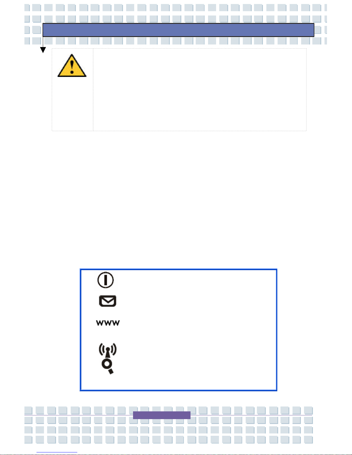
Power Button: To turn your
Notebook power ON and OFF.
Quick Launch Buttons: Simply
click the quick launch buttons
to speedup the starting of the
programs in common use. It
helps you to work more
efficiently.
Caution: To avoid damage to the system’s components
caused by electrical surges, plug your system into a
surge protector. During an electrical storm, unplug
both the surge protector from the power outlet and the
telephone line from the phone jack.
Page 28

28
Preface
Powering Off Information
Prior to shutting down your TransPort
®
U1100, ensure all of your data
and current work are saved. To turn off the TransPort
®
U1100:
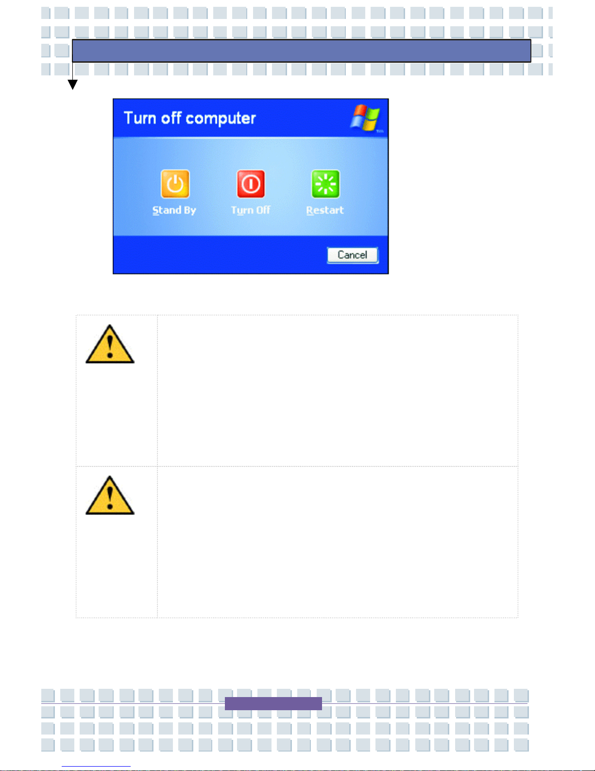
Click Start on the taskbar.
1. Click Turn Off Computer.
2. Click Turn Off to complete the shutdown sequence.
Note: If you need to restart your TransPort
U1100 after software (re)installation or because i
t
is not responding, select the Restart option.
Page 29
29
Preface
Caution: If the [Ctrl+Alt+Delete] keys do not operate
either, press the power button for more than 5 seconds
to turn off the TransPort U1100. Your unsaved work
may be lost/damaged. When you turn on the TransPort
U1100 next time, it will perform a disk checking
p
rocess.
Caution: If you need to turn the TransPort U1100 on
again immediately after turning it off, wait at least five
seconds. This will give the hard disk drive and optical
drives a chance to spin down. Turning the power off
and on rapidly can damage the TransPort U1100.
Page 30
30
Preface
Caution: If the TransPort U1100 is not turned off
p
roperly due to a system error, press
[Ctrl+Alt+Delete]. When the Windows Task Manager
dialog box appears, click Shut Down > Turn Off to
turn off the TransPort U1100. Your unsaved work
may be lost/damaged.
Standby or Hibernation Mode
When you finish a working session, you can power down the TransPort
®
U1100 by turning off the TransPort
®
U1100 or placing the TransPort®
U1100 in Standby or Hibernation mode.
Standby, unlike Hibernation mode, does not store unsaved information
on your hard disk; unsaved information is stored only in the TransPort
®
U1100 memory. If there is an interruption in power, the information is
lost. Before putting your TransPort
®
U1100 in Standby mode, you should
save your files.
Page 31
31
Preface
Standby/Hibernation Mode Actions
To stop in this
mode…
Do this… To start up or resume
again…
Off
Follow the operating
system's shutdown
procedure.
If the system is locked
up because of hardware
or software problems,
press the power button
to turn off the
TransPort
®
U1100.
Press the power
button.
Standby
Depending on your
Windows settings, you
can put the TransPort
®
U1100 in Standby mode
by:
closing the
display cover
pressing
[Fn+Esc]
pressing the
power button
Press the power
button.
Hibernation Follow the operating
system's shutdown
procedure.
Press the power
button.
If you choose to stop working and put your system into Standby or
Hibernation mode, you can return to where you left off the next time you
start up the TransPort
®
U1100. See Power Management for more
information.
Page 32
32
Preface
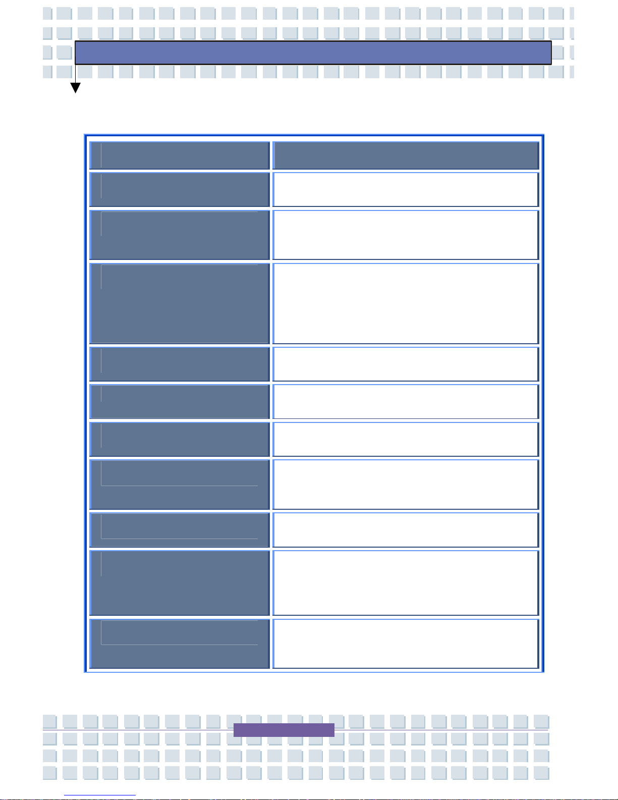
Specifications
Description
Display
12.1-inch WXGA TFT LCD (1280x800)
Operating System
Windows® XP Professional or Windows
Vista™ Business
Processor
Intel® Centrino, Intel® Core 2 Duo
processor, 667FSB T5600 (1.83GHz
2MB Cache) or T7400 (2.16GHz 4MB
Cache)
Processor Packaging
micro FCPGA
Chipset
Intel 945GM
System Bus
667MHz front side bus
Memory
Two SO-DIMM's: 512MB 667MHz DDR
SDRAM, expandable to 2GB
Expansion Slots
One MiniCard for wireless option
Graphics
Integrated Intel® Media Accelerator 950
Graphics (DVMT, up to 224MB shared
memory)
System Bays
1 optical bay, 1 battery bay, 1 hard drive
bay
Page 33
33
Preface
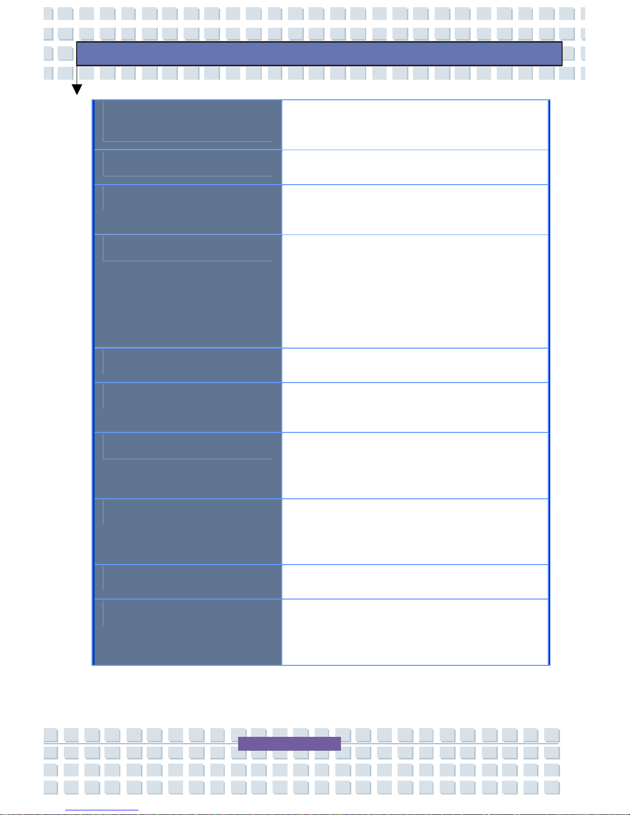
Fixed Optical Bay
Options
DVD/CDRW Combo or DVD Multi Drive
(DVD-RW/+RW/CD-RW)
Hard Disk Drive
PATA, 40, 60, 80,100 or 120GB 5400
RPM
Audio
Realtek ALC 882H, Dolby support, builtin 1.5W speakers
Communications
Integrated MDC 56Kbps V.92
fax/modem & 10/100/1000 Base-T LAN
with built in RJ-45 and RJ-11 jacks.
Internal Bluetooth. Internal antennae for
Intel PRO/Wireless 3945ABG
802.11a/b/g card.
Keyboard
86-key keyboard (19mm pitch)
Pointing Device
Two-button touchpad with 2-way scroll
functionality
Built-In I/O Ports
(3) USB 2.0, VGA (monitor), RJ-11, RJ45, Mic-In, Headphone-Out, 4-pin
firewire port
Additional Features
4 hot keys: E-mail, Internet, Wireless
LAN/Bluetooth, and Explorer (Search)
buttons
PC Card Support
Express Card
Media Reader
3-in-1 media reader supports Memory
Stick, Secure Digital, and Multi Media
cards
Page 34
34
Preface
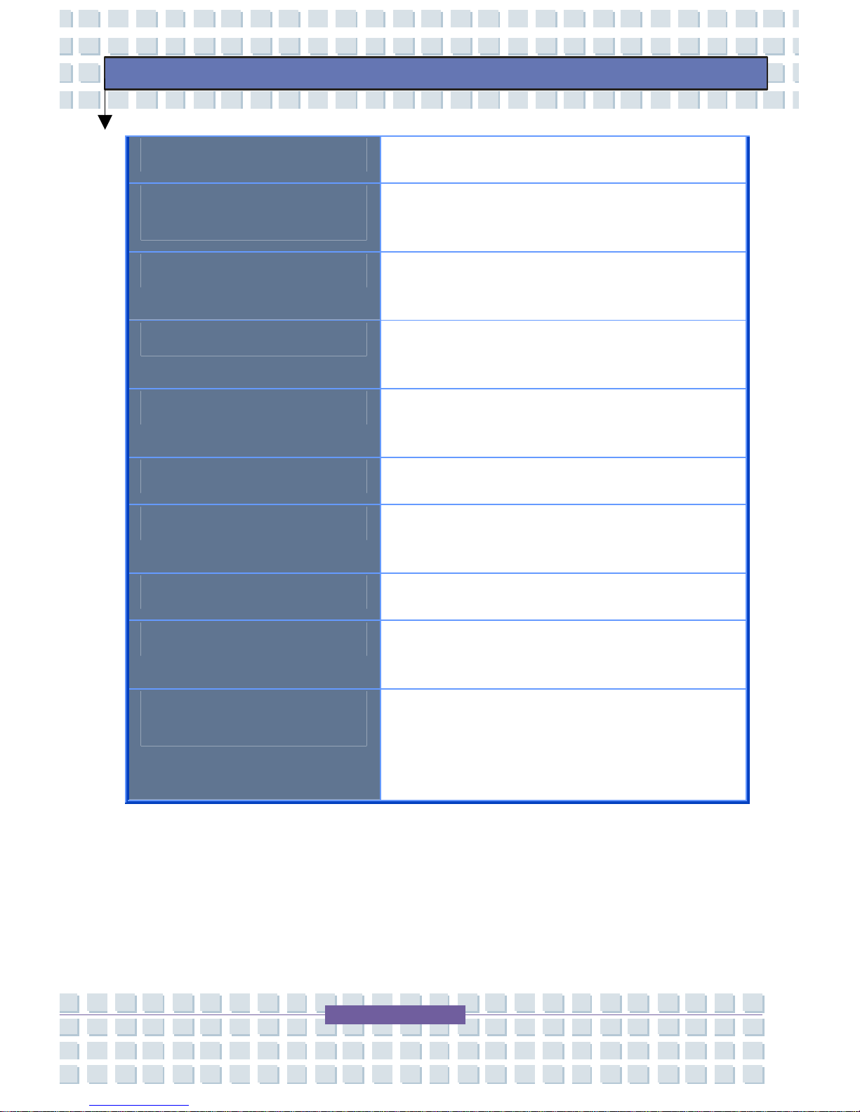
Primary Battery
Removable 4- or 8-cell Smart Li-Ion
Secondary Batteries
Additional
Additional 4-cell Smart Li-Ion
(2400mAH)
Additional 8-cell Smart Li-Ion (4400mAh)
AC Adapter
65W output, 19V DC; Automatic voltage
adjustment 100-240V, 50/60Hz AC
Power Management
Hibernation, Suspend, Sixteen-level
panel brightness, Battery gauge display
Chassis
Plastic lid, top case, base, and LCD
bezel
Dimensions
11.9" (W) x 8.86" (D) x 1.18" (H)
System Weight
4.3lbs (includes 4-cell battery, HDD,
Combo Drive)
Security
Kensington Lock Slot
Regulatory/Certifications
Energy Star, Novell, UL, FCC, RoHS,
WEEE
Supporting
Documentation
CD with Electronic Manual, Readme
files, Drivers; Windows CD; Easy Set-Up
Guide; System Safety Manual; Warranty
Flyer.
Page 35
35
Preface
TransPort® U1100 Features
Your MPC TransPort® U1100 is a lightweight portable Notebook that
includes features to meet your computing needs at home or on the road.
The following sections in this chapter will help you locate and identify the
connectors and components on your TransPort
®
U1100.
Note: The appearance, location, and existence of
the components mentioned may vary by model.
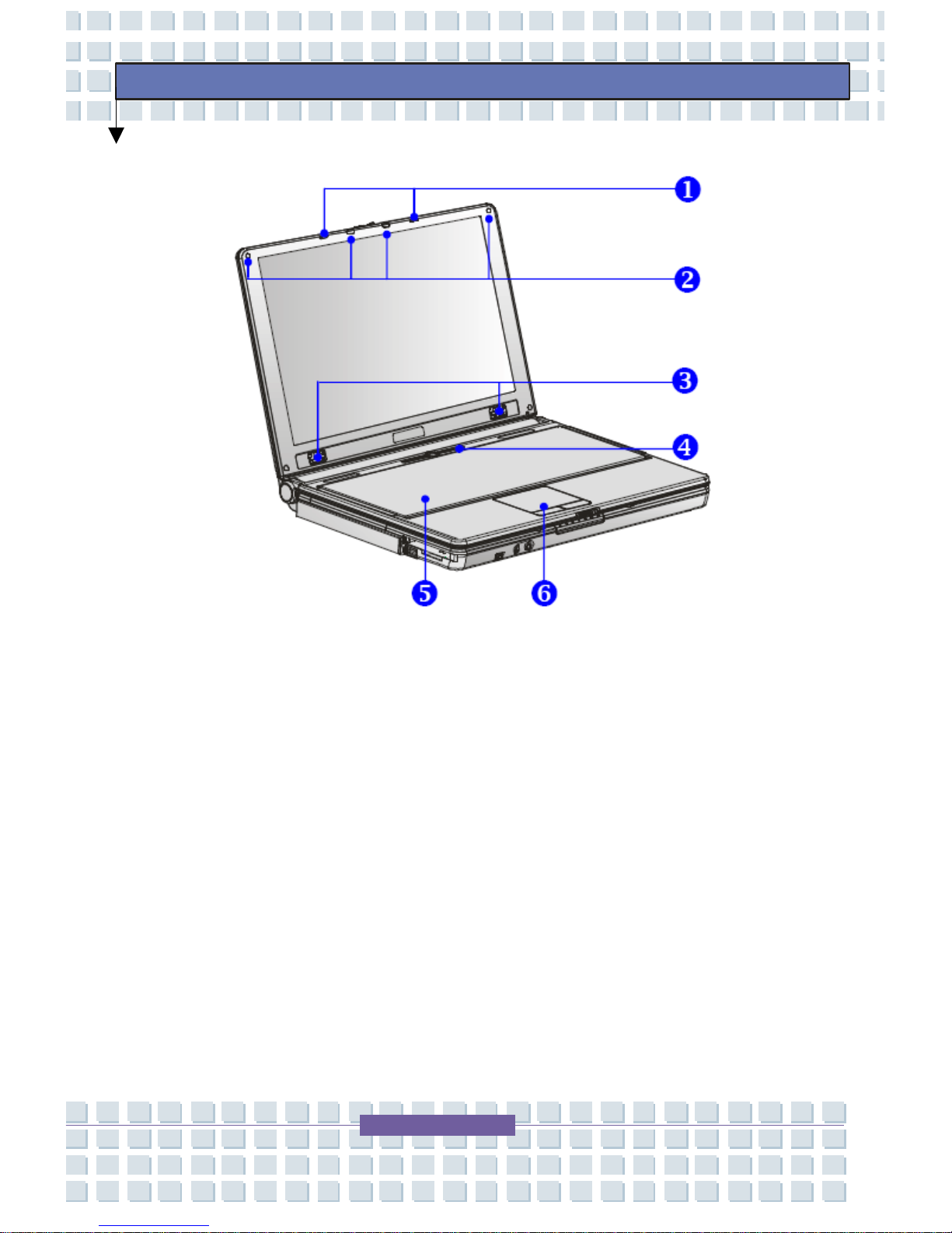
Top Open View
Press the Cover Latch to open the top cover (LCD Panel). The figure of
top-open view and description shown below will let you browse the main
operating area of your Notebook.
Page 36
36
Preface
Top Open View
1. Cover Latch (Internal View)
2. Rubber Pads
3. Stereo Speakers
4. Quick Launch Buttons and Power Button
5. Keyboard
6. Touchpad
Page 37
37
Preface
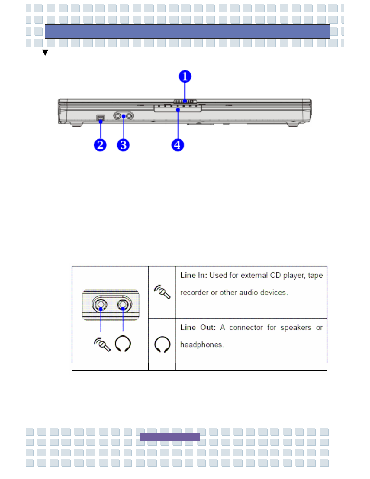
Front View
1. Cover Latch (External View) – Slide the LCD latch to the right
and lift the LCD panel.
2. IEEE 1394 Port – High-speed bus that allows you to connect
high-end digital devices such as the DV (digital video camera).
3. Audio Port Connectors – Make high quality sound blaster with
stereo system and Hi-Fi function supported.
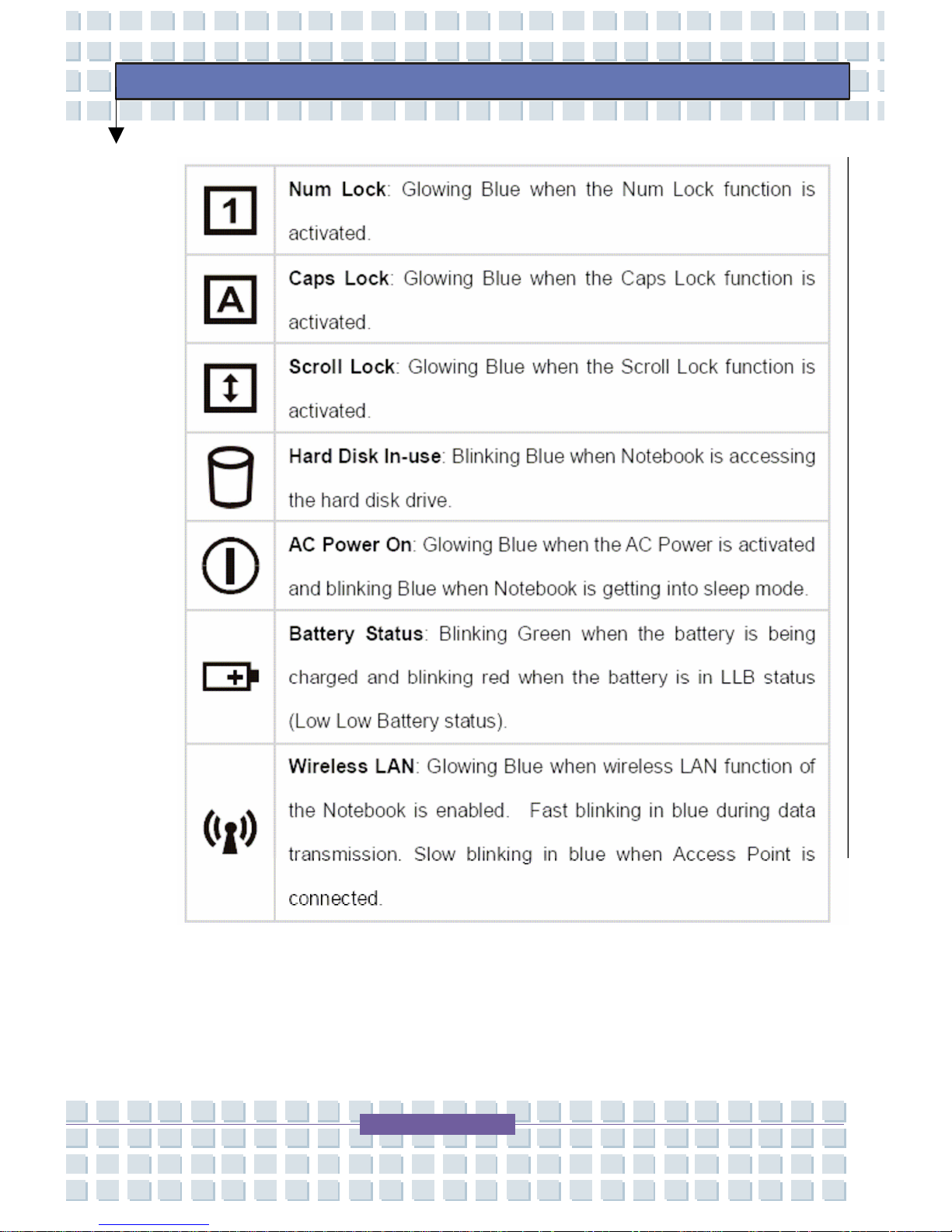
4. Status LED
Page 38
38
Preface
Page 39
39
Preface
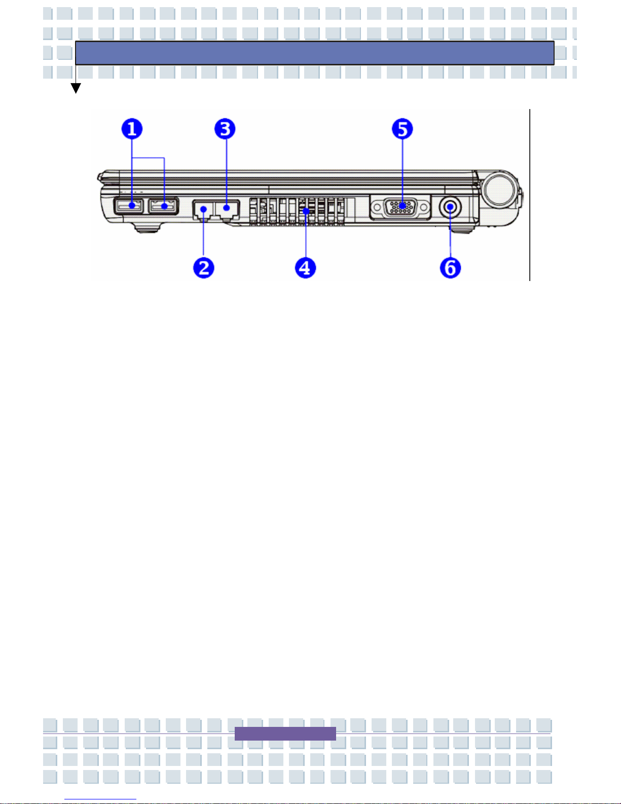
Right-Side View
1. USB Port – The USB 2.0 port allows you to connect USB-
interface peripheral devices--the mouse, keyboard, modem,
portable hard disk module, printer, and more.
2. RJ-11 Connector – The TransPort
®
U1100 provides a builtin modem allowing connection to an RJ-11 telephone line
through this connector. With the 56K V.90 modem, you can
make a dial-up connection.
3. RJ-45 Connector - The 10/100/1000 Ethernet connector is
used to connect a LAN cable for network connection.
4. Ventilator – The ventilator is designed to cool the system.
DO NOT block the ventilator for air circulation.
5. VGA Port – The 15-pin-D-sub VGA port allows you to
connect an external monitor or other standard VGAcompatible device (such as a projector).
6. Power Connector – Connects the AC adapter and su pplies
power.
Page 40
40
Preface
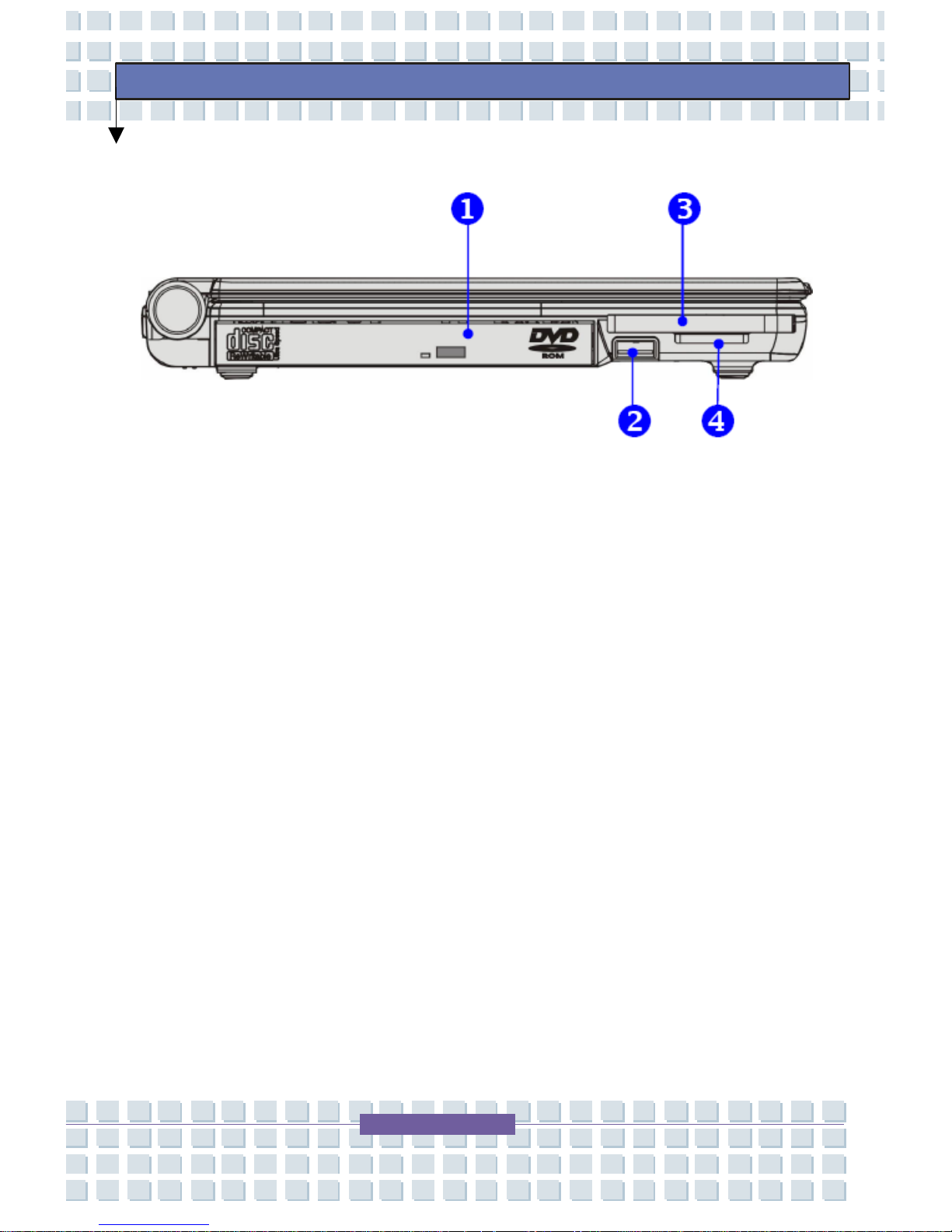
Left-Side View
1. Optical Storage Device – A slim DVD Combo or Super
Multi Drive is available in the Notebook, depending on the
model you purchased. The optical device allows you to use
the CD/DVD disc for installing software, accessing dat a and
playing music/movie on the Notebook.
2. USB Port – The USB 2.0 port allows you to connect USB-interface
peripheral devices, such as the mouse, keyboard, modem, portable hard
disk module, printer and more.
3. Express Card Slot – The computer provides an Express
Card slot. The new Express Card interface is smaller and
faster than PC Card Interface. The Express Card technology
takes advantage of the scalable, high-bandwidth serial PCI
Express and USB 2.0 interfaces.
4. 3-in-1 Card Reader – The built-in card reader supports MIC
(multi-media card), SD (secure digital) and MS (memory
stick) cards.
Page 41
41
Preface
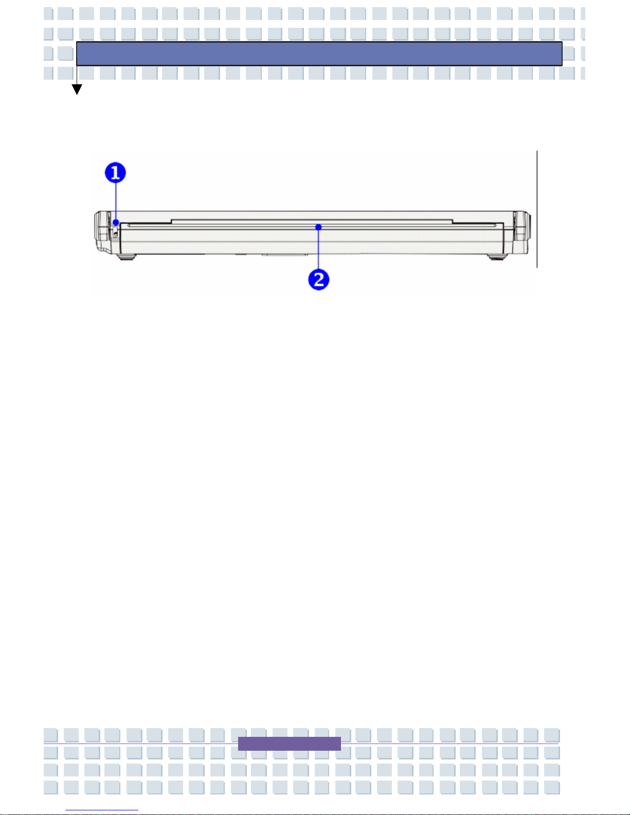
Rear View
1. Kensington Lock Hole – This is used to lock the
TransPort
®
U1100 for security.
2. Battery Pack (Rear View) – The battery pack supplies
power to your TransPort
®
U1100 when the adapter is not
connected.
Page 42
42
Preface
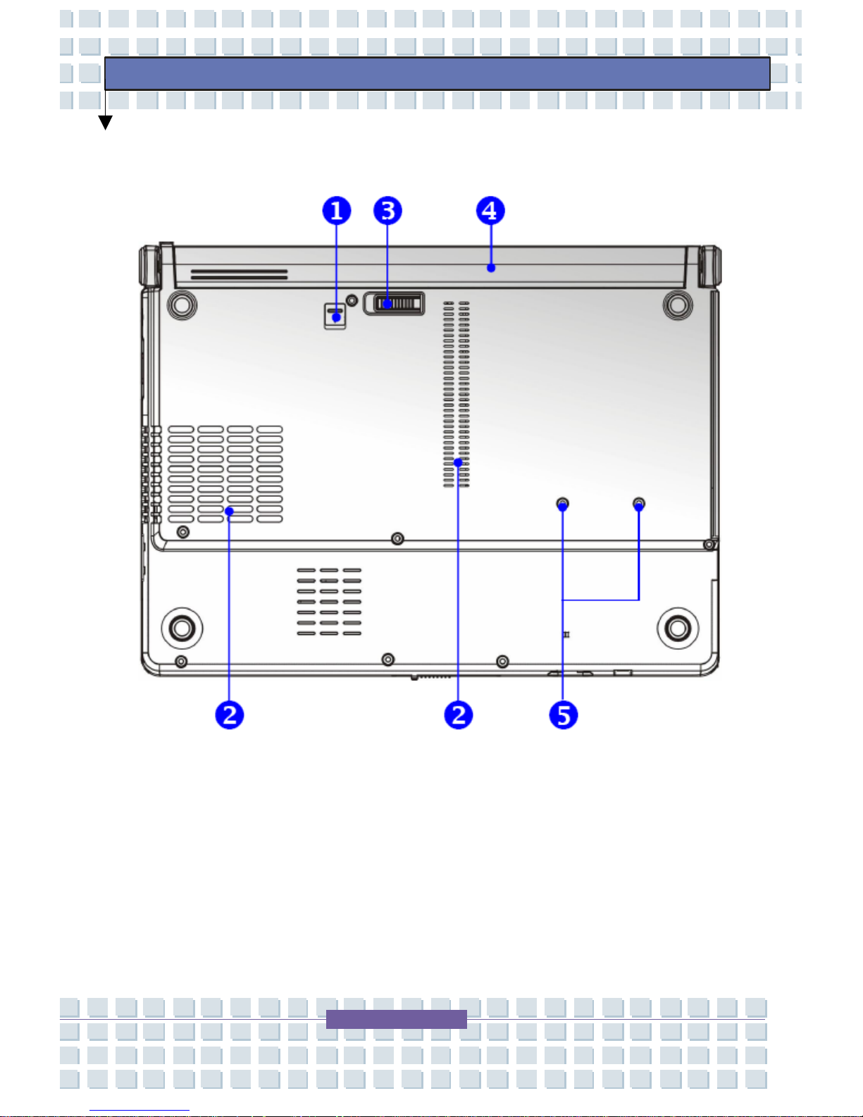
Bottom View
1. Battery Lock/Unlock Button – Battery cannot be moved
when the button is positioned on lock status. Once the button
is pushed to unlock position, the battery is removable.
2. Ventilator – The ventilator is designed to cool the system.
DO NOT block the ventilator for air circulation.
Page 43

43
Preface
3. Battery Release Button – It is a bounce-back device which
releases the battery pack. Press it with one hand and pull the
battery pack carefully with the other.
4. Battery Pack – Supplies power to your TransPort
®
U1100
when the AC adapter is not connected.
5. Screw Box for Releasing Optical Device – Use
screwdriver to remove Optical Device from the notebook.
Page 44

44
Preface
Power Management
Your TransPort® U1100 includes Power Management options that can
help the battery charge last longer and extend the life of the battery.
Power-management options will slow down or shut off system
components when the components are not being u sed. Power
management may slow down system performance. Your TransPort
®
U1100 runs fastest with the power cord attached, causing power
management to be disabled. This chapter explains how to effectively
manage power. To maintain optimal battery performance, it is important
that you use the battery properly.
AC Adapter
It is strongly recommended to connect the AC adapter and use the AC
power while using the TransPort
®
U1100 for the first time. When the AC
adapter is connected, the battery is being charged immediately. The AC
adapter included in the package is approved for your Noteboo k; using
other adapter models may damage the Notebook or other devices on the
Notebook.
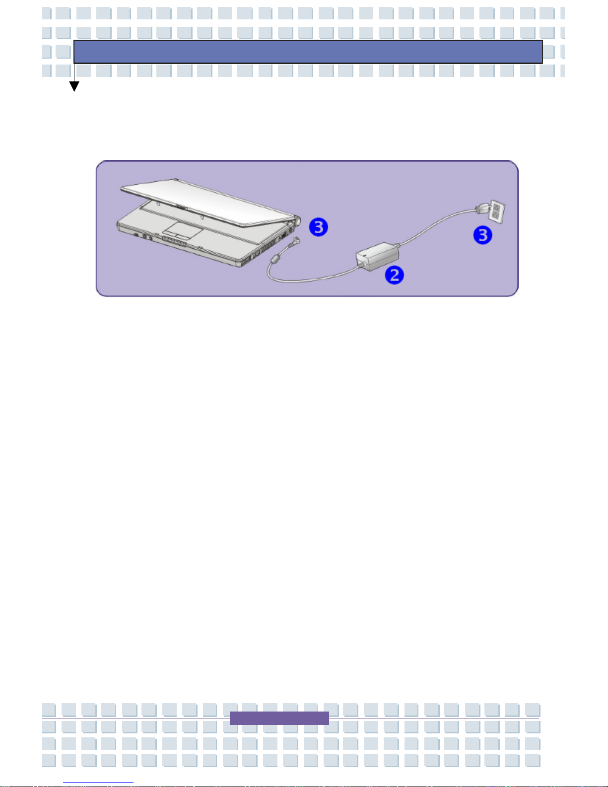
Connecting the AC Power
1. Unpack the package to find the AC adapter and power cord.
2. Attach the power cord to the connector of the AC adapter.
Page 45
45
Preface
3. Plug the DC end of the adapter to the Notebook, and the male
end of the power cord to the electrical outlet.
Disconnecting the AC Power
1. Unplug the power cord from the electrical outlet first.
2. Unplug the connector from the Notebook.
3. Disconnect the power cord and the connector of AC adapter.
4. When plugging in the power cord, always hold the connector part
of the cord. Never pull the cord directly.
Battery Pack
This Notebook is equipped with a high-capacity 4-cell or 8-cell Li-ion
Battery pack. The rechargeable Li-ion battery pack is an internal power
source of the Notebook.
Page 46

46
Preface
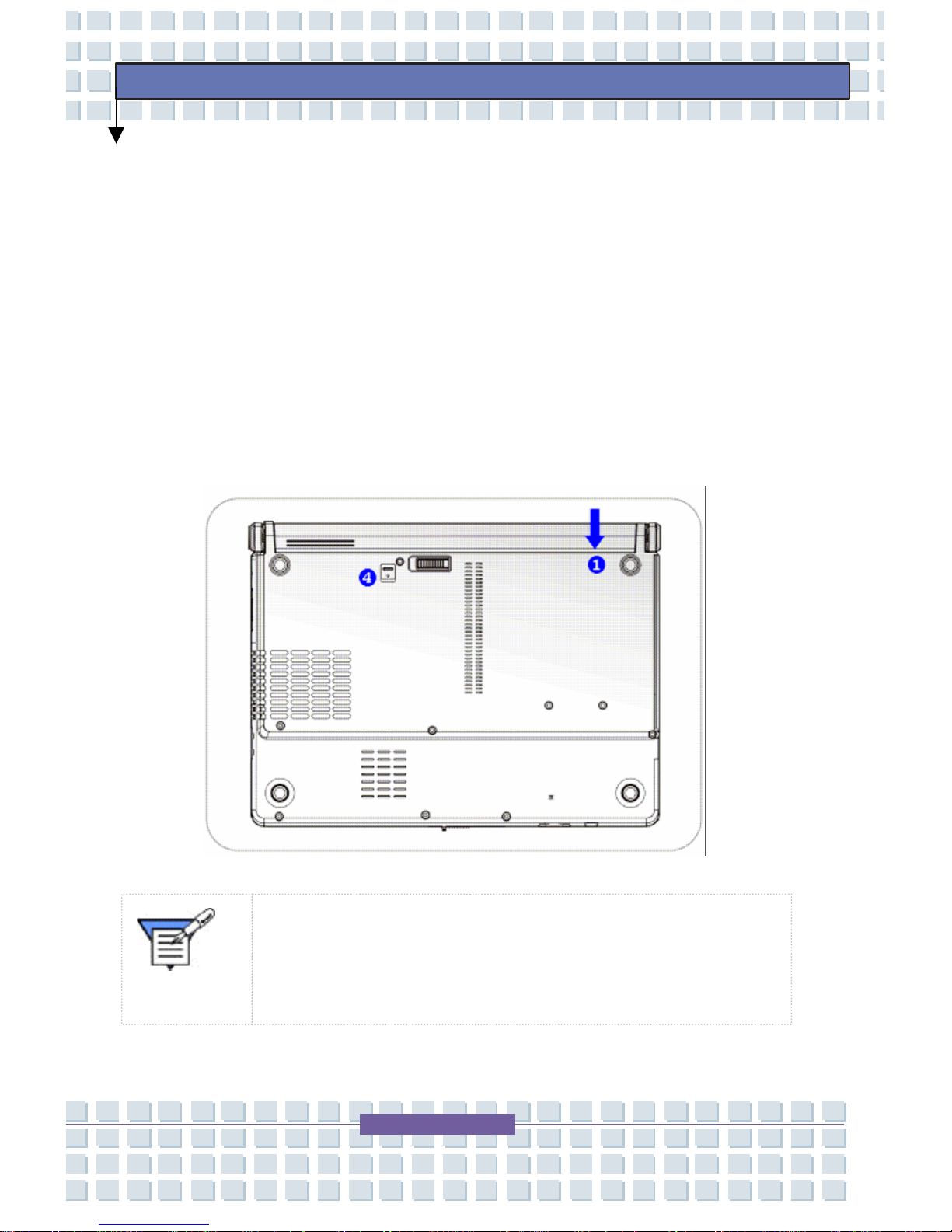
Releasing the Battery Pack
You can purchase an extra battery pack from your MPC Sales
Representative as a backup to the battery pack that came with your
Notebook.
To remove the battery pack:
1. Make sure the Notebook is turned off.
2. Put the Lock/Unlock button is in unlocked status.
3. Locate the Battery Release Button on the bottom side.
4. Push the Release Button to the direction of the arrow below
the button.
5. Slide the left side of the battery pack first out of the
compartment and then pull the right side of the battery pack.
Page 47
47
Preface
Replacing the Battery Pack
1. Insert the right side of battery pack into the compartment.
2. Slightly slide and press the battery pack into the right place.
3. Align the right side of the battery into the right track, and then
slightly press the left side of battery pack into the battery
chamber.
4. Make sure the Lock/Unlock Button is in lock position.
Note: Do not try to disassemble THE BATTERY PACK.
Please follow your local laws and regulations to recycle
the unused battery pack.
Page 48

48
Preface
Using the Battery Pack
Battery Safety Tips
Replacing or handling the battery incorrectly may present a risk of fire or
explosion, which could cause serious injury.
Only replace the main battery pack with the same or equivalent
type of battery.
Do not disassemble, short-circuit or incinerate batteries or
expose them to temperatures above +60° C (+140° F).
Do not temper with batteries. Keep them away from children.
Do not use rusty or damaged batteries.
Dispose of batteries according to local regulations. Check with
your local solid waste officials for details about recycling for
proper disposal in your area.
Conserving Battery Power
Efficient battery power is critical to maintain a normal operation. If the
battery power is not managed well, the saved data and customized
settings may be lost.
Follow these tips to help optimize battery life and avoid a sudden power
loss.
Suspend system operation if the system will be idle for a while or
Page 49

49
Preface
shorten the Suspend Timer’s time period.
Turn off the system if you won’t be using it for a period of time.
Disable unneeded settings or remove idle peripherals to conserve
power.
Connect an AC adapter to the system whenever possible.
Charging the Battery Pack
The battery pack can be recharged while it is installed in the Notebook.
Please pay attention to the following tips before recharging the battery:
If a charged battery pack is not available, save your work and
close all running programs and shut down the system or Save-toDisk.
Plug in an external AC/DC power source.
You can use the system, suspend system operation, or shut down
and turn off the system without interrupting the charging process.
The battery pack uses Lithium-ion battery cells that have no
“memory effect.” You do not need to discharge the battery pack
before you begin charging. However, to optimize the life of the
battery, consuming the battery power completely once a month is
necessary.
If you do not use the Notebook for a long time, it is suggested to
remove the battery pack from your Notebook. This may be
helpful to extend your battery life.
The actual charging time is determined by the applications use.
Page 50
50
Preface
Using the Main System Battery Safely
Caution To avoid damage to your notebook, use only
an MPC supplied or approved battery for your specific
notebook model.
Follow these guidelines to safely use the battery:
Turn off your notebook and unplug it if you accidentally:
Expose the equipment to liquid.
Drop, jar, or damage the notebook.
Use only approved battery chargers.
Do not disassemble the battery, heat it above 212° F (100°C), or
burn it. The battery used in this notebook may cause a fire or
chemical burn if mistreated.
Your notebook's rechargeable battery may be considered
hazardous waste. If you replace your battery with a new one:
Keep the old battery out of the reach of children.
Dispose of the old battery promptly.
Make sure that you follow all federal, state, and local
requirements when you dispose of the old battery.
Page 51
51
Preface
Your Computer’s CMOS Battery Care
CMOS (complementary metal-oxide semiconductor) is a semiconductor
chip located on the motherboard, which is powered by a battery
dedicated to supporting the CMOS, “CMOS Battery.” The CMOS stores
information such as the system time and system settings for your
computer.
Caution: The CMOS battery is not rechargeable;
to avoid costly repairs to replace the CMOS
battery you should take the following
p
recautions.
The system requires periodic use in order to ensure the intended
lifespan of the CMOS battery. Ideally, this requires periodic
operation of the system using either the main system battery or
the AC Adapter
Storage of the notebook without use for any period of time is not
recommended.
Page 52

52
Preface
If absolutely necessary, storing the notebook requires
precautions to ensure the intended lifespan of the CMOS battery.
Please take the following precautions:
Do not store your notebook without use for longer than thirty
days.
Remove the main battery from the notebook.
Plug in the AC Adapter and connect to an electrical outlet.
Set the laptop to off.
Page 53
53
Preface
Keyboard and Touchpad
Keyboard
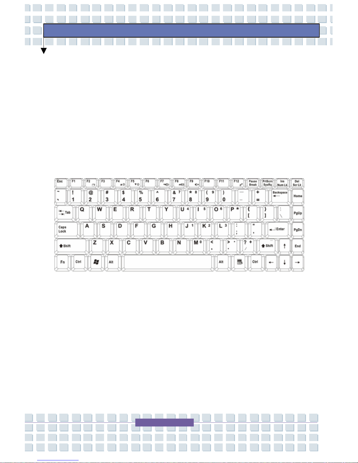
The Notebook’s keyboard provides all the functions of a full-sized 86-key
keyboard and an additional [Fn] key for specific functions on the
Notebook. The keyboard can be divided into four categories: Typewriter
keys, Cursor keys, Numeric keys and Function key s.
Page 54
54
Preface
Typewriter Keys
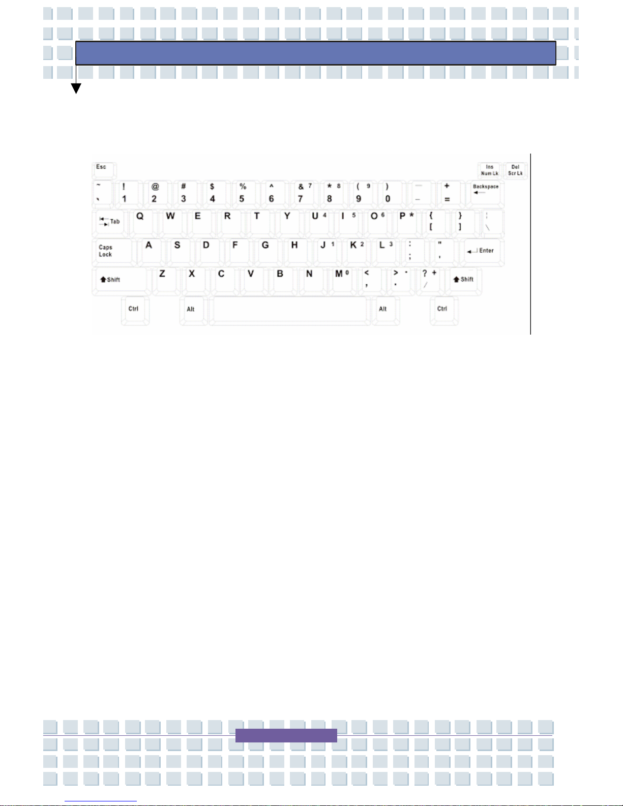
The function of these Typewriter keys is the major function of the
keyboard, which is similar to the keys on a typewriter. It also provides
several keys for special purposes, such as the [Ctrl], [Alt] and [Esc] key.
When the lock keys are pressed, the corresponding LEDs will light up to
indicate their status:
Num Lock: Press and hold the [Fn] key and press this key to
toggle the Num Lock on and off. When this function is activated,
you can use the numeric keys that are embedded in the
typewriter keys.
Caps Lock: Press this key to toggle the Caps Lock on and off.
When this function is activated, the letters you type are kept in
uppercase.
Page 55
55
Preface
Scroll Lock: Press and hold the [Fn] key and press this key to
toggle the Scroll Lock on and off. Individual programs define this
function and it is usually used under DOS.
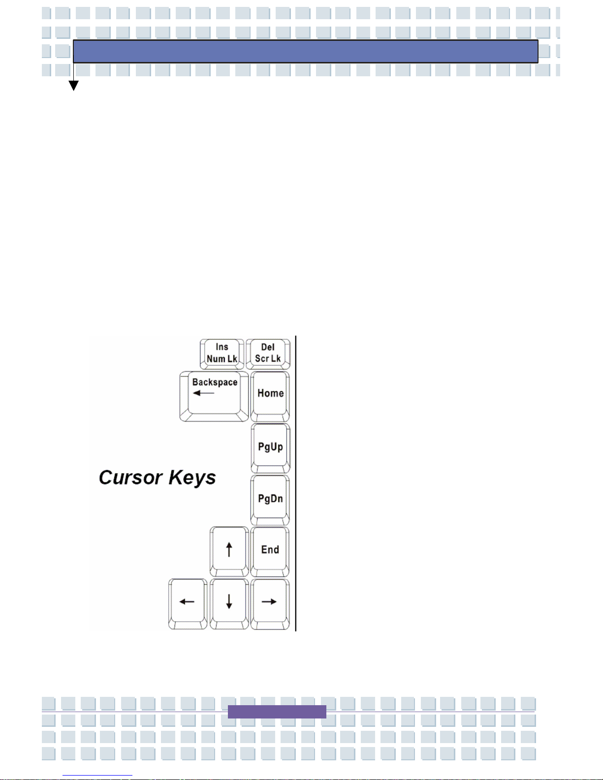
Cursor Keys
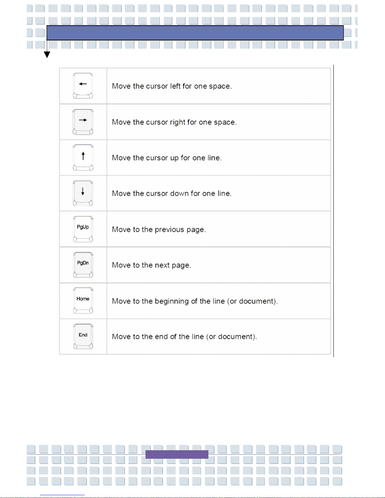
The keyboard provides four cursor (arrow) keys and [Home], [PgUp],
[PgDn], [End] keys at the lower right corner, which are used to control
the cursor movement.
Page 56
56
Preface
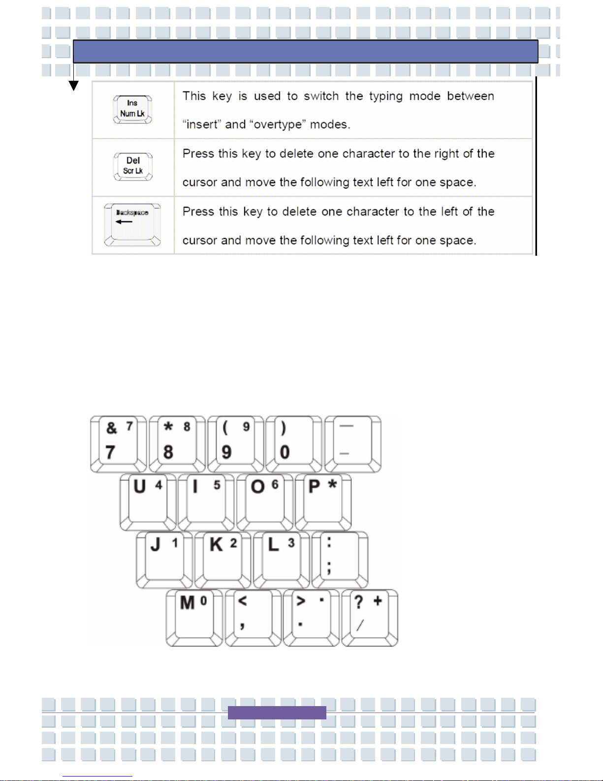
The backspace key, [Ins] and [Del] keys at upper right corner are use for
editing purpose
.
Page 57
57
Preface
Numeric Keys
The keyboard provides a set of numeric keypad, which is embedded in
the typewriter keys. When the Num Lock is activated, you can use these
numeric keys to enter numbers and calculations.
Page 58
58
Preface
Function Keys
Window Keys
You can find the Windows Logo key ( ) and one Application Logo key ( ) on the
keyboard, which are used to perform Windows-specific functions, such as opening the Start
menu and launching the shortcut Windows manual or online help.
Page 59
59
Preface
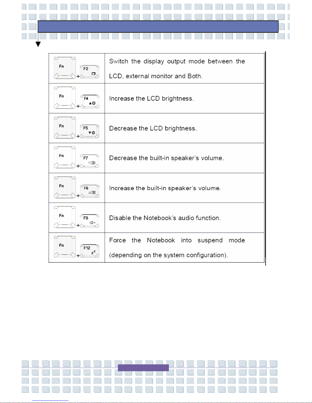
[Fn] Key
Page 60
60
Preface
Touchpad
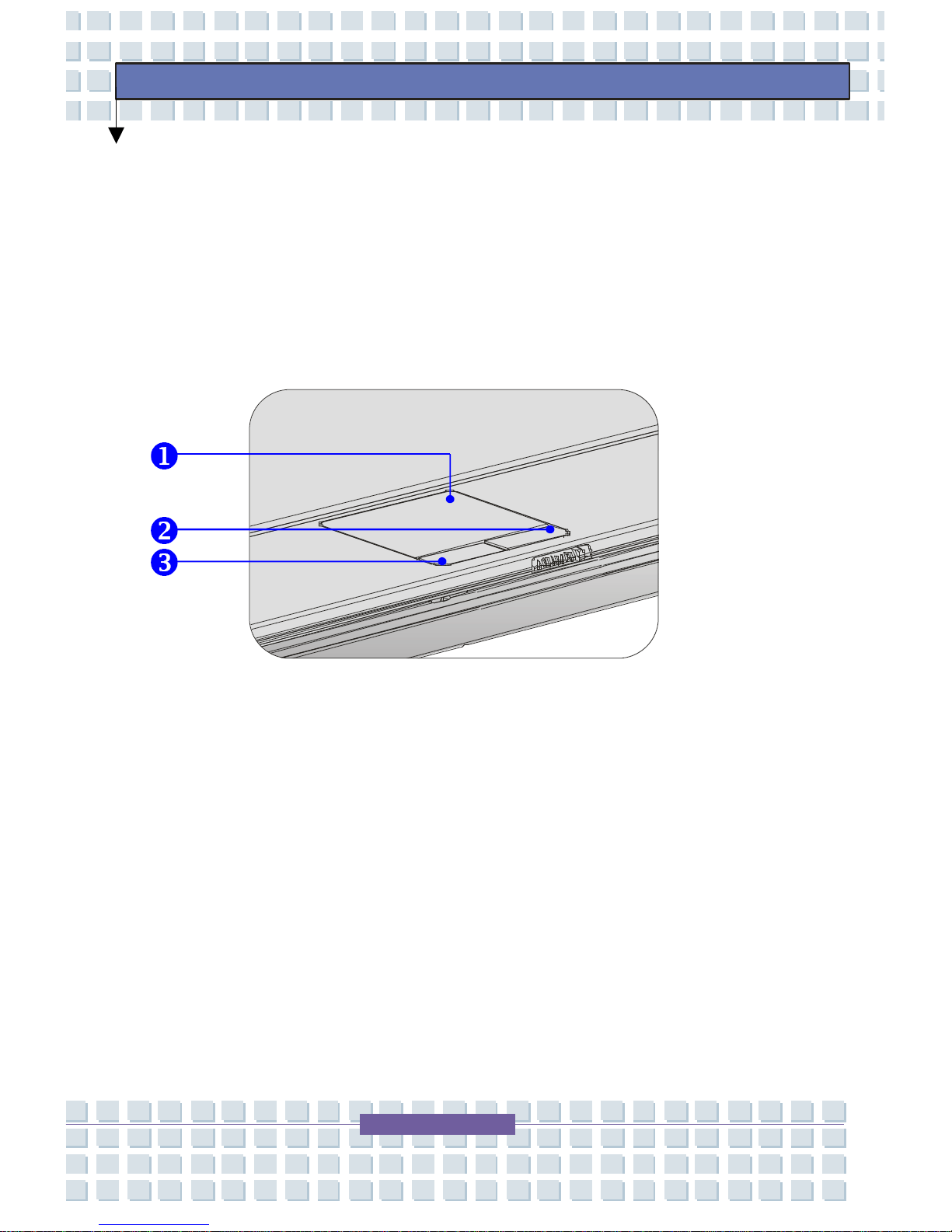
The touchpad integrated in your Notebook is a pointing device that is
compatible with standard mouse, allowing you to control the Notebook by
pointing the location of the cursor on the screen and making selection
with its two buttons.
1. Cursor Movement Area – This pressure-sensitive area of
the touchpad, allows you to place your finger on it and
control the cursor on the screen by moving your finger.
2. Right Button – Acts as the mouse’s right button.
3. Left Button – Acts as the mouse’s left button.
Page 61

61
Preface
Using the Touchpad
Positioning and Moving
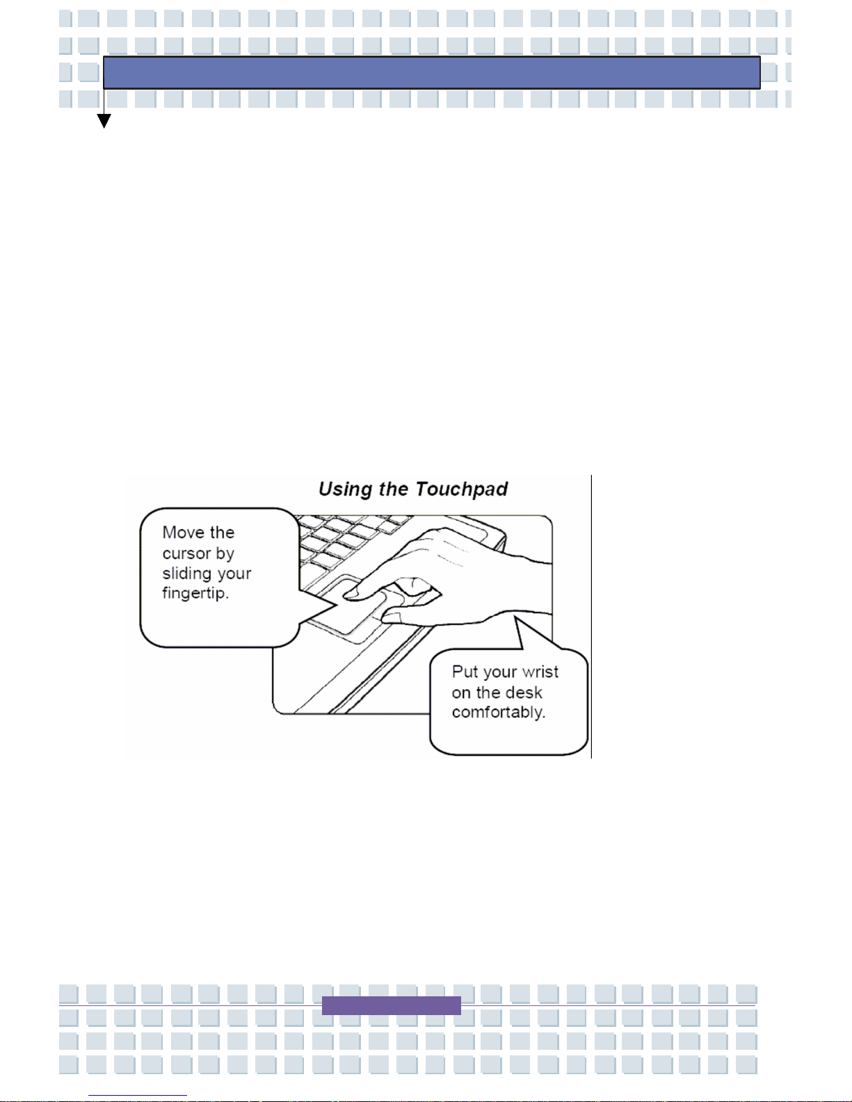
Place your finger on the touchpad (usually using the forefinger) and the
rectangular pad will act as a miniature duplicate of your display. When
you move your fingertip across the pad, the cursor on the screen will
move simultaneously in the same direction. When your finger rea ches
the edge of the pad, lift your finger and replace it on a proper location of
the touchpad.
Point and Click
When you have moved and placed the cursor over an icon, a menu item
or a command that you want to execute, simply tap slightly on the
touchpad or press the left button to select. This procedure, called point
and click is the basics of operating your TransPo rt
®
U1100. Unlike the
traditional pointing device such as the mouse, the whole touchpad can
act as a left button--each tap on the touchpad is equivalent to pressing
the left button. Tapping twice rapidly on the touchpad is equivalent to a
double-click.
Page 62
62
Preface
Drag and Drop
You can move files or objects in your Notebook by using drag-and -drop.
To do so, place the cursor on the desired item and slightly tap twice on
the touchpad, and then keep your fingertip in contact with the touchpad
on the second tap. Now, you can drag the selected item to the desired
location by moving your finger on the touchpad, and then lift your finger
from the touchpad to drop the item into place. Alternately, you can press
and hold the left button when you select an item, and then move your
finger to the desired location; finally, release the left button to finish the
drag-and-drop operation.
Page 63
63
Preface
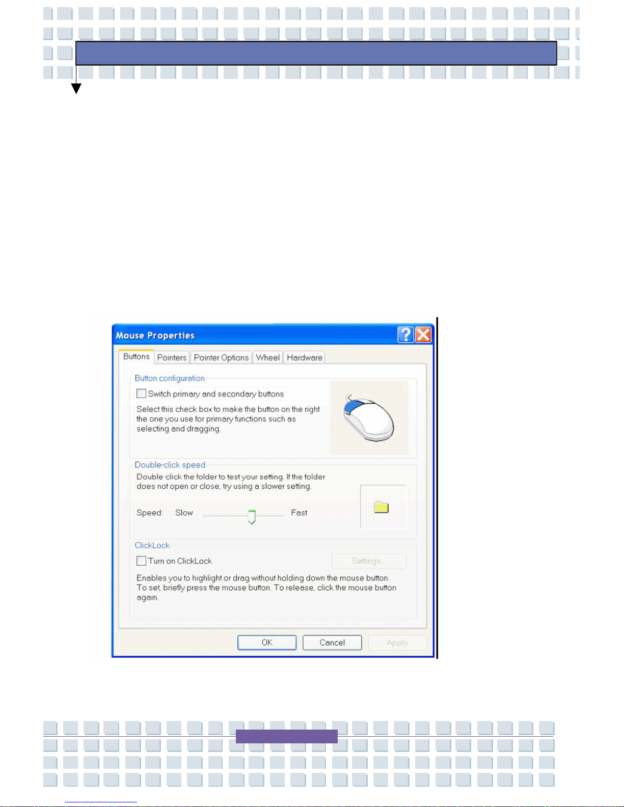
Configuring the Touchpad
You can customize the pointing device to meet your personal needs. For
example, if you are a left-hand user, you may want to swap the functions
of the two buttons. In addition, you can change the size, shape, moving
speed, and other advanced features of the cursor on the screen.
To configure the touchpad, you can use the standard Microsoft or IBM
PS/2 driver in your Windows operating system. The Mouse Properties in
the Control Panel allow you to change the configuration.
Page 64
64
Preface
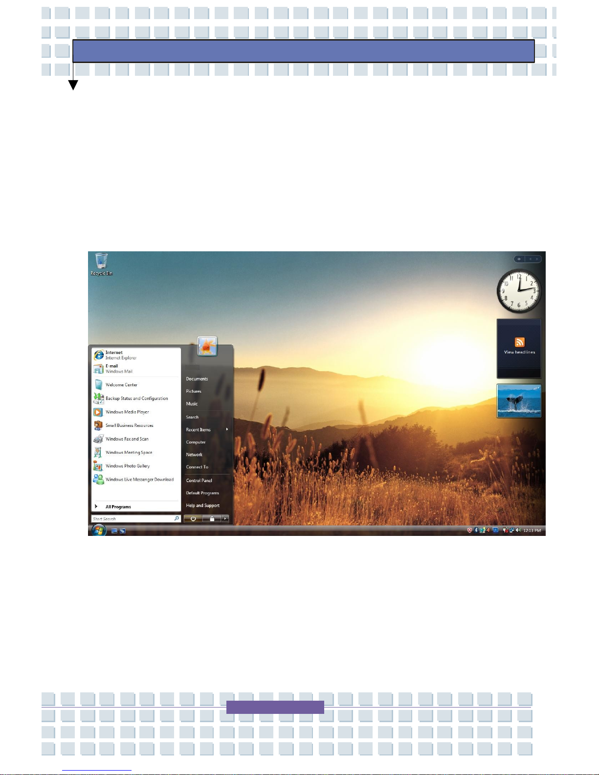
Windows Vista™ Business
The following sections in this chapter provide informati on on using the
Windows Vista™ Business operating system.
Desktop
Page 65
65
Preface
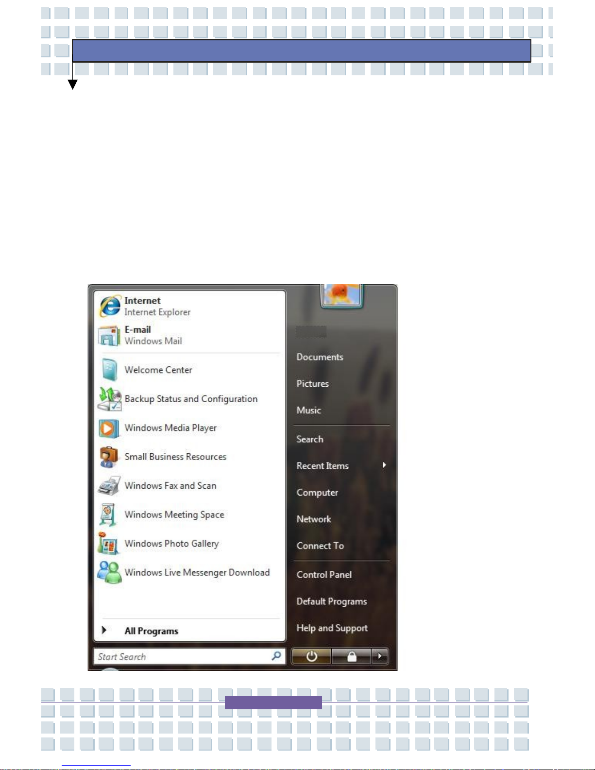
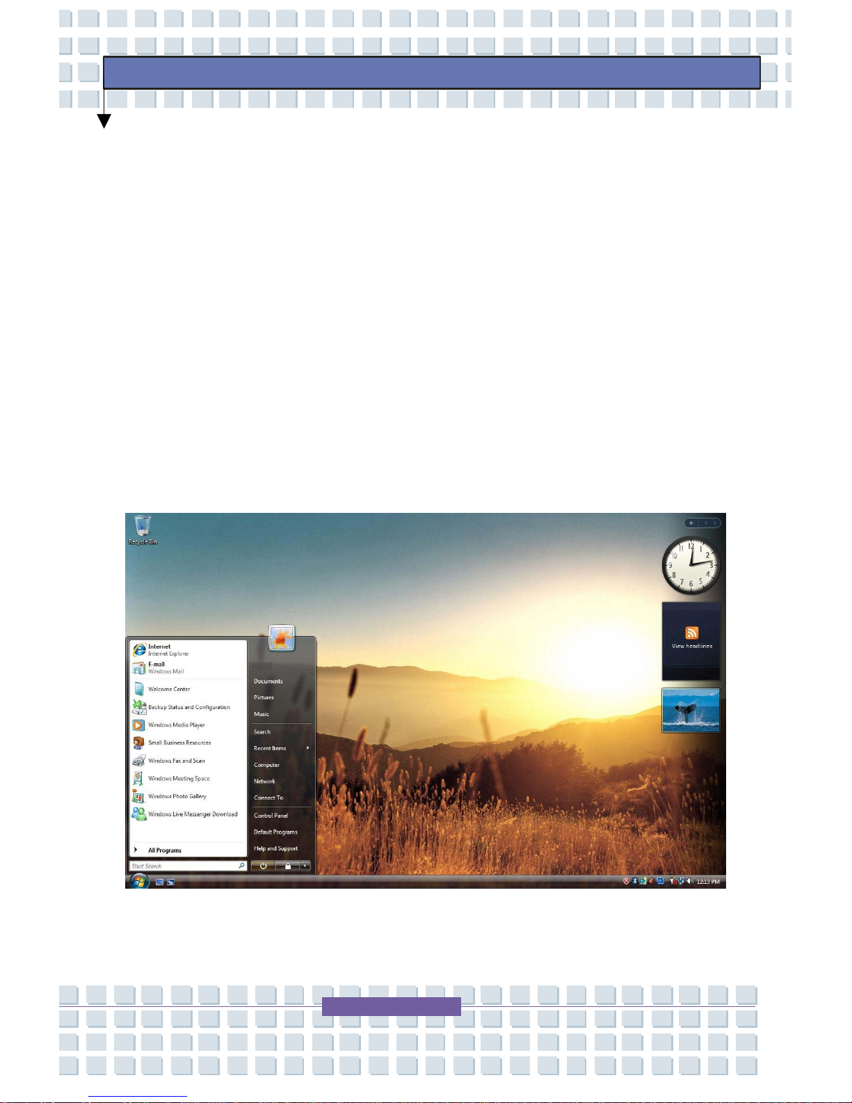
Start Menu
The Start Menu includes everything that is required to start Windows.
From the Start Menu it is possible to run a program, open a file, assign
system users with Control Panel, receive support by clicking Help and
Support, and search desired items from the TransPort
®
U1100 or
Internet by clicking Search.
Start Menu
Page 66
66
Preface
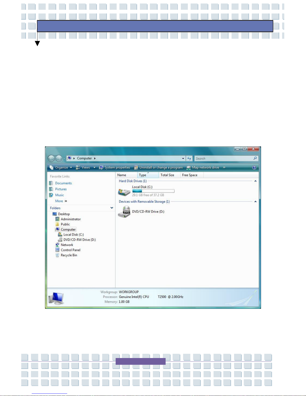
Window
A window is the basic component in working with the TransPort® U1100.
The My Computer window, which is a window for the TransPort
®
U1100’s hard drive, will be used as an example here to show the basic
composition of a window.
Click Start>My Computer.
My Computer Window
Page 67

67
Preface
Double click the hard drive (local disk) to view internal folders and
files stored in it. If the contents do not appear, click Show Contents
of this Folder.
What is a drive?
A drive is a storage device in which files and folders are saved and
read.
What is a folder?
A folder is used to group and manage files systematically. A folder
may include files in sub-folders.
What is a file?
A file is a document or various kinds of material that is generated as
a result of program operation. It is also called data.
To view the entire structure of the drive:
Click the Folder icon in the taskbar to view the entire structure. Click
again to return to the Quick Task Window.
Page 68
68
Preface
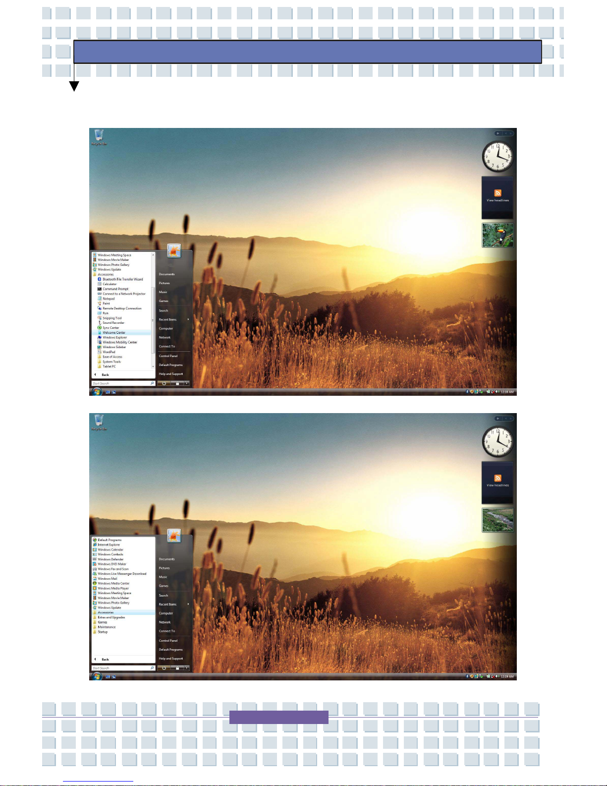
Tour
You can tour elementary functions provided by Windows Vista™
Business.
Click Start > Tour Windows Vista Business.
Or
Click Start > All Programs > Accessories > Tour Windows Vista
Business.
Click on the topics to find out about important functions of Windows
Vista™ Business.
Desktop
Page 69
69
Preface
Accessories
Page 70
70
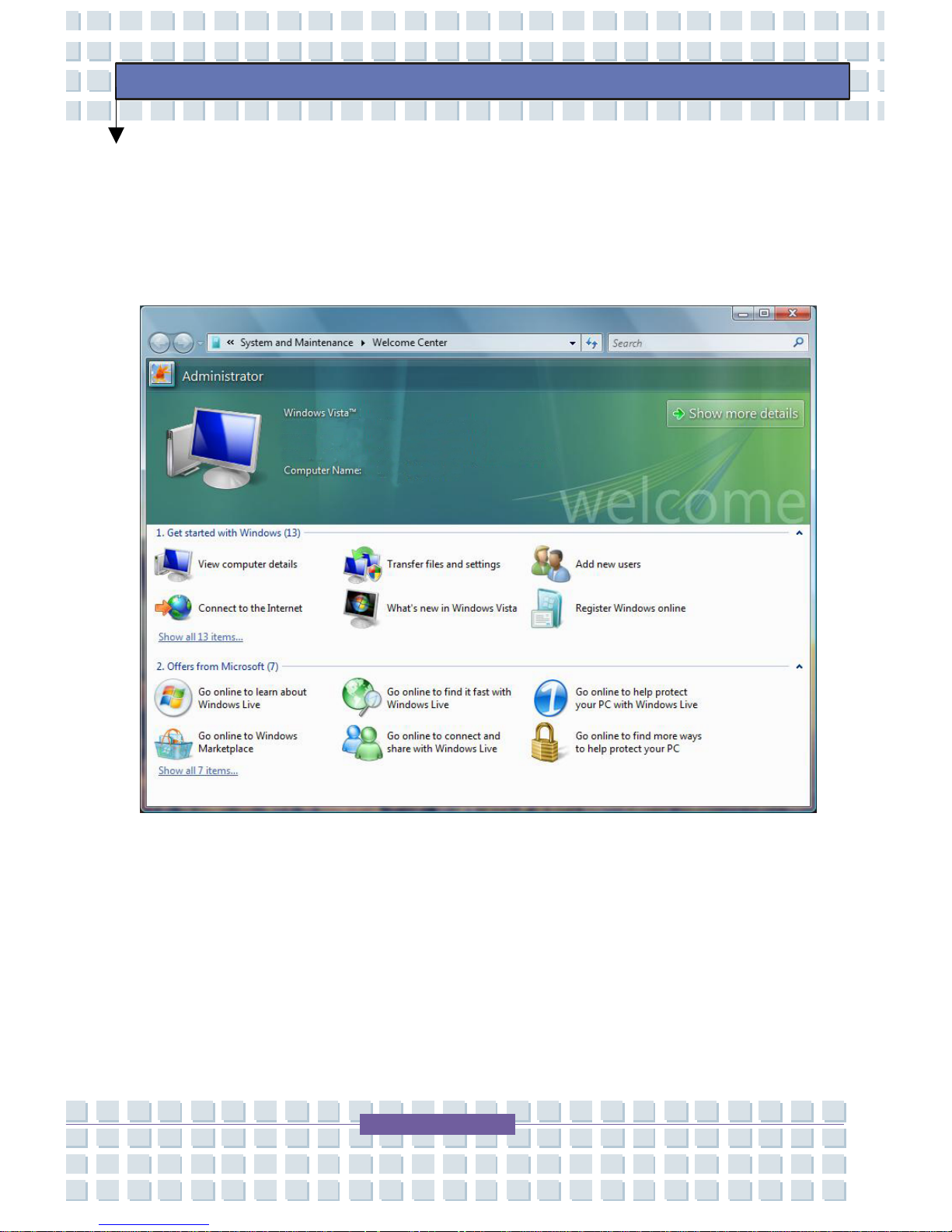
Preface
Welcome Center
For more detailed information on Windows Vista™, click on the Show
more details link.
Page 71
71
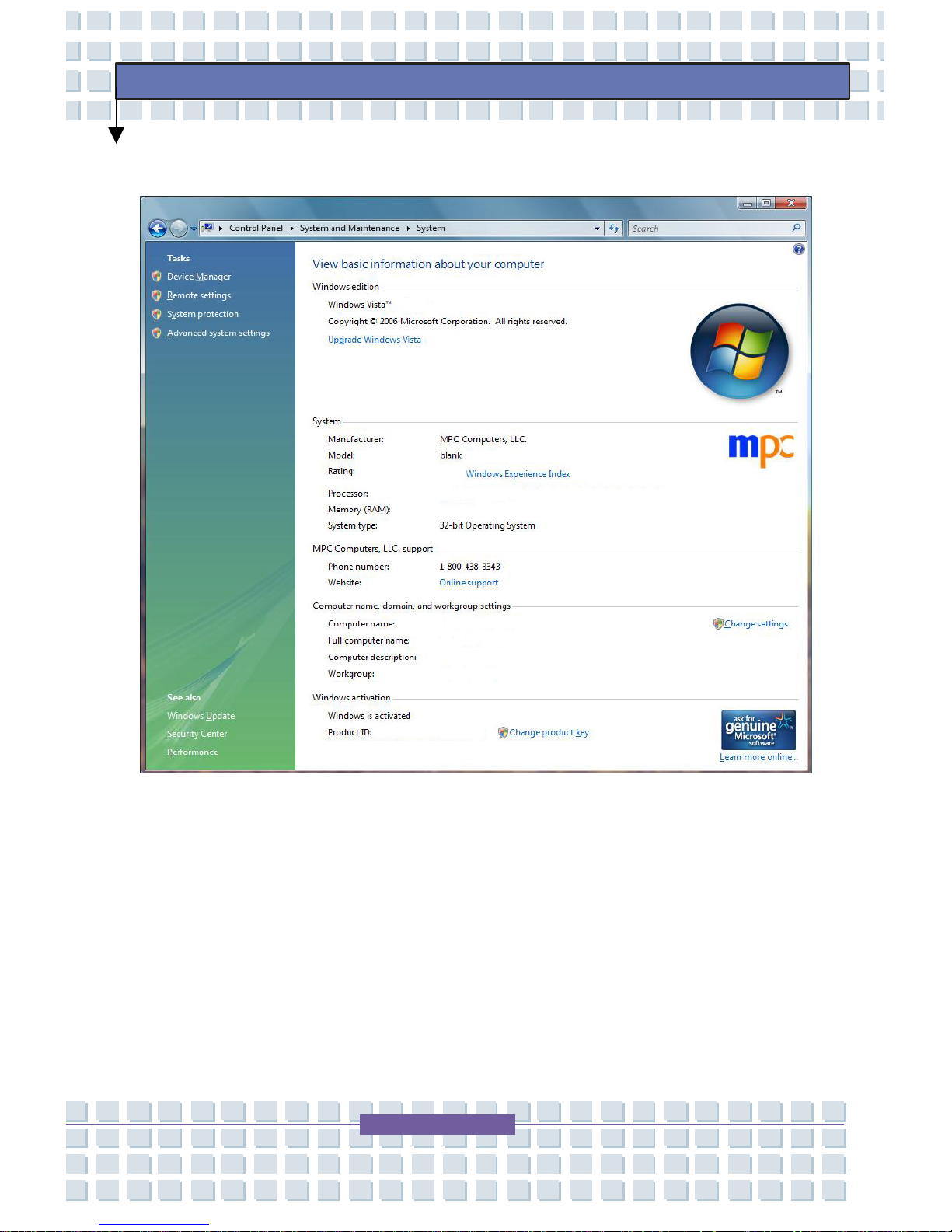
Preface
Welcome Center Advanced
Page 72
72
Preface
Peripheral Devices
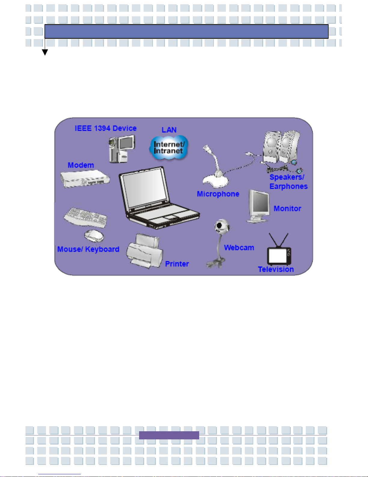
The I/O (input/output) ports on the TransPort® U1100 allow you to
connect peripheral devices.
Connecting the Peripheral Devices
Connecting the Mouse
You can connect a mouse to your TransPort® U1100 through the USB
port. If your mouse requires a PS/2 connection, purchase a PS2/USB
connector first. To connect the mouse:
Page 73

73
Preface
1. Turn on the TransPort® U1100 and install the mouse driver.
2. Connect your mouse to the TransPort
®
U1100.
3. The TransPort
®
U1100 may auto detect your mouse driver and
enable the mouse function. If there is no detection of your mouse
you can manually enable the mouse by going to Start Menu
Control Panel Add Hardware to add the new device.
Connecting the Keyboard
You can connect a keyboard to your Notebook through the USB port. If
your keyboard requires a PS/2 connection, please p urchase a PS/2-USB
connector first. To connect the keyboard:
1. Turn on the TransPort
®
U1100 and install the keyboard driver.
2. Connect your keyboard to the Notebook.
3. The Notebook may auto detect your keyboard driver and enable
the keyboard function. If there is no detection of your keyboard,
you can manually enable the keyboard by going to Start Menu
Control Panel Add Hardware to add the new device.
Connecting the WebCam
You can connect a WebCam to your Notebook thro ugh the USB port. To
connect the WebCam:
1. Turn on the TransPort® U1100 and install the WebCam driver.
2. Connect your WebCam to the Notebook.
Page 74

74
Preface
3. The Notebook may auto detect your WebCam driver and enable
the WebCam function. If there is no detection of your WebCam,
you can manually enable the WebCam by going to Start Menu
Control Panel Add Hardware to add the new device.
Connecting the Printer
If your printer has a USB interface, you can then use the USB port on the
TransPort
®
U1100 to connect a printer. Follow the instructions below to
connect a printer:
1. Turn off the TransPort
®
U1100.
2. Connect one end of the printer cable to the USB port and the
other end to the printer.
3. Connect the power cord and turn on the printer.
4. Turn on the TransPort
®
U1100 and the system will detect a new
device. Install the required driver.
For further instructions, please refer to your printer’s manual.
Connecting the External Monitor or TV
You can connect an external monitor to your Notebook through the VGA
port for a larger view with higher resolution. To connect the monitor:
1. Make sure that the TransPort
®
U1100 is turned off.
2. Plug the monitor’s D-type connector into the VGA port.
3. Connect the monitor’s power cord and turn on the monitor.
Page 75

75
Preface
4. Turn on the TransPort® U1100 and the monitor should respond
by default. If not, you can switch the display mode by pressing
[Fn]+[F2]. Alternately, you can change the display mode by
configuring the settings in Display Properties of Windows
®
operating system.
Connecting the IEEE 1394 Devices
The IEEE 1394 port of your TransPort® U1100 is a next-generation serial
bus that features a high-speed transfer rate and the connection of up to
63 devices, allowing you to connect many high-end peripheral devices
and consumer electronic appliances, such as the DV (digital video
camera). The IEEE 1394 standard interface supports “plug-and-play”
technology, so that you can connect and remove the IEEE 1394 devices
without turning off the Notebook. To connect the IEEE 1394 device,
simply connect the cable of the device to the IEEE 1394 port of your
TransPort
®
U1100.
Page 76
76
Preface
Connecting the Communication Devices
Using the LAN
The RJ-45 connector of the TransPort® U1100 allows you to connect the
LAN (local area network) devices, such as a hub, swit ch and gateway, to
build a network connection. This built-in 10/100/1000 Base-T LAN
module supports data transfer rate up to 1000Mbps. For mo re
instructions or detailed steps on connecting to the LAN, please consult
your Internet service provider (ISP) for help.
Using the Modem
The built-in 56Kbps fax/data modem allows you to use a telephone line to
communicate with others or to dial-up to connect the Internet. For more
instructions or detailed steps on dialing-up through the modem, please
consult your Internet service provider (ISP) for help.
Note: To reduce the risk of fire, use only No. 26
A
WG or larger telecommunication lone cord.
Note: Install the modem driver included in the
software CD of the TransPort U1100 to take full
advantage of the modem feature.
Page 77

77
Preface
Express PC Card Installation
This computer provides an Express Card slot. The new Express Card
interface is smaller and faster than PC Card interface. The Express Card
technology takes advantage of the scalable, high-bandwidth seri al PCI
Express and USB 2.0 interfaces.
The following instruction provides you with a basic installation for the
Express Card, including how to install and remove it. For more
information, please refer to the manual of your Express Card.
Installing the Express Card
1. Locate the Express Card slot on your notebook. If there is the
dummy card in the slot, remove it first.
2. Insert the Express Card into the slot (usually with its label facing
up) and push it until it is firmly seated.
Removing the Express Card
1. Press the edge of the Express Card to make the card stretch out
a bit.
2. Pull the Express card out of the slot.
3. Reattach the dummy card back into the slot.
Page 78
78
Preface
Safely Remove Hardware
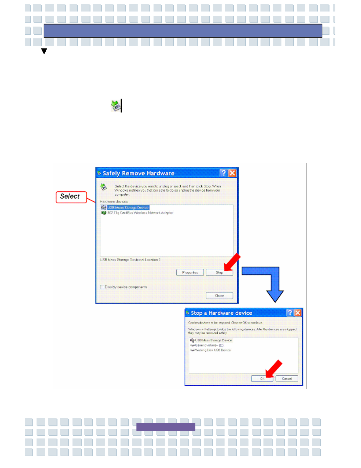
If you connect any peripheral device to your system, the Safely Remove
Hardware icon (
) will appear on the taskbar. Double-click the icon to
bring up the Safely Remove Hardware dialog box. You can see all
connected peripheral devices here. If you want to remove any of the
devices, move the cursor to the device and click Stop.
Page 79
79
Preface
BIOS Setup
When to Use BIOS Setup?
You may need to run the BIOS Setup when:
An error message appears on the screen during the system
booting and requests you to run SETUP.
You want to change the default settings for customized features.
You want to reload the default BIOS settings.
How to Run Bios Setup?
To run the BIOS Setup Utility, turn on the TransPort
®
U1100 and press
the [Del] key during the POST procedure. If the message disappears
before you respond and you still wish to enter Setup, restart the system
by turning it OFF and ON, or simultaneously pressing [Ctrl]+[Alt]+[Delete]
keys to restart.
Note: The actual setting screens and options on
your TransPort may be different because of BIOS
update.
Page 80
80
Preface
Control Keys
Page 81
81
Preface
BIOS Setup Menu
Once you enter the BIOS Setup Utility, the Main menu will appear on the
screen. The Main menu displays the system information, including the
basic configuration.
1. Main Menu – Show System Overview information about
BIOS version, CPU features, Memory size and setting of
System Time and Date.
2. Advanced Menu – Configure IDE and USB settings.
3. Boot Menu – Set up Boot Type and Boot Sequence.
Page 82
82
Preface
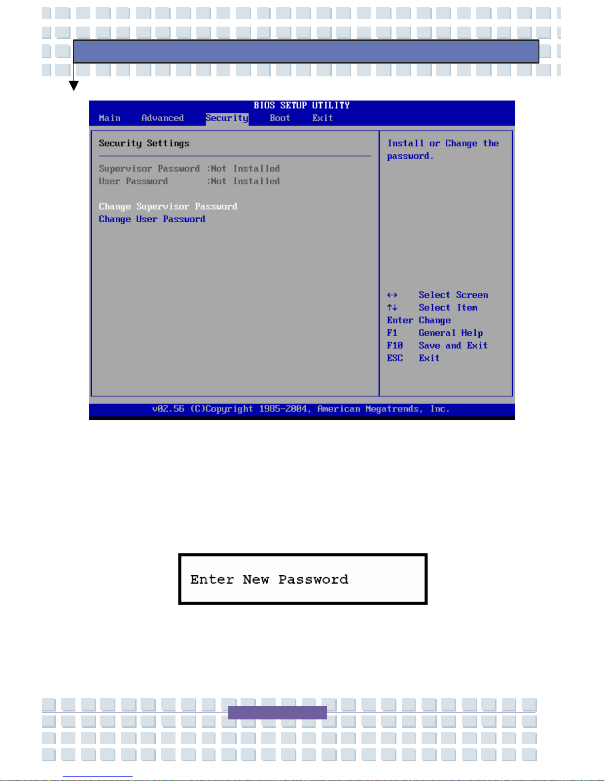
4. Security Menu – Install or clear Supervisor’s and User’s
Password settings.
5. Exit Menu – Choose decided status before leaving the BIOS
menu.
Main Menu
System Overview
System Overview will show you BIOS version and other information
about its build date and update notes, CPU type and speed, and system
memory. The variable setting s in Main menu are Share Memory, System
Time, and System Date.
Page 83

83
Preface
System Memory – This item details the information of System
Memory.
System Time – This item allows you to set the system time. The
system clock will go on even if the PC is shut down or in sleep
mode. The set format is [hour:minute:second].
System Date – This item allows you to set the system date. The
date format is [day:month:date:year].
Day: Day of the week from Sun to Sat, which is
determined by BIOD (read-only).
Month: The month from 01 (January) to 12
(December)
Date: The date from 01 to 31.
Year: users can adjust the year.
Page 84
84
Preface
Advanced Menu
Page 85
85
Preface
Page 86
86
Preface
Advanced Settings
Primary IDE Master/Slave – These two items display the types
of the primary IDE master/slave devices installed in the
TransPort
®
U1100. Press [Enter] to bring up a window showing
the detailed information of the device, including the device name,
vendor, LBA mode, PIO mode, and more.
Legacy USB Support – If you want to use a USB device, such
as a mouse, keyboard, or portable disk in your DOS system or
Page 87

87
Preface
boot your system by a USB device, you should enable this
function by selecting Enabled.
Intel
®
SpeedStep™ Tech – This item allows you to enable or
disable Intel SpeedStep technology. When set to Disabled, the
system always operates in a conserve power mode (the
processor works at FSB400 or FSB533). If you want to optimize
the processor, set this item to Enabled, so that the processor’s
speed will be controlled by the use of your operating system and
applications.
Page 88
88
Preface
Security Menu
Security Settings
Change Supervisor/User Password – when you select this
function, a message box will appear on the screen as below:
Type the password you want up to six characters in length and
press [Enter]. The password typed now will replace a ny
Page 89
89
Preface
previously set password from CMOS memory. You may also
press [ESC] to abort the selection and n ot enter a password.
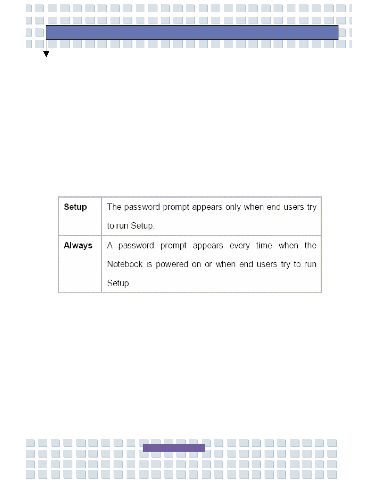
When the Supervisor Password is set, the new item User Access Level
and Password Check will be added in the menu. You can make furthe r
settings of access right in the User Access Level item. Setting options:
No Access, View Only, Limited, and Full Access. The Password
Check item is used to specify the type of BIOS password protection that
is implemented. Settings are described below:
To clear a set password, just press [Enter] when you are prompted
to enter the password. A message box will show up confirming the
password will be disabled. Once the password is disabled, the
system will boot and you can enter Setup without entering any
password.
Supervisor Password allows the user to enter and change the
settings of the setup menu; User Password only allows the user to
enter the setup menu, but not to make changes.
Page 90
90
Preface
Boot Menu
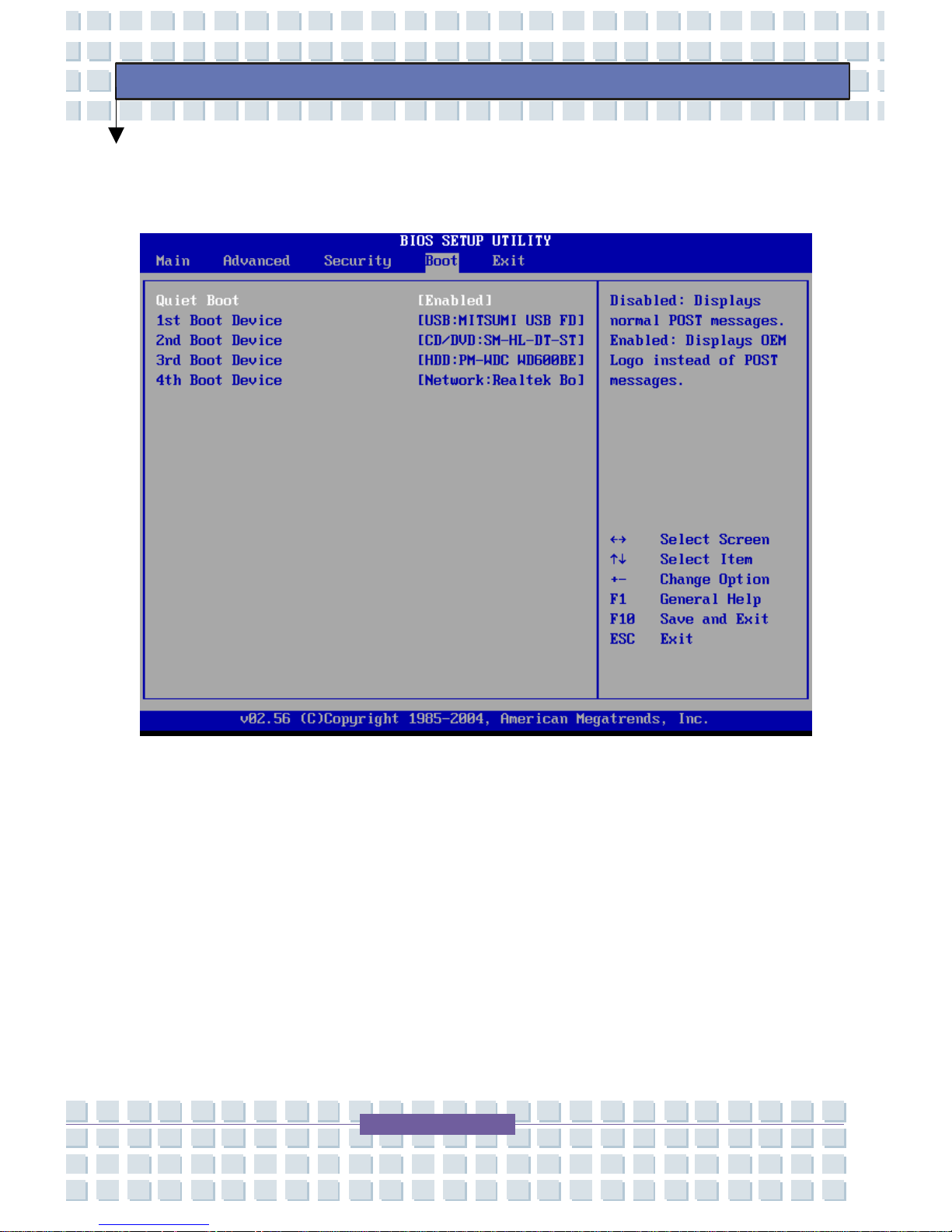
Quiet Boot – This item enables you to show the vendor logo on
the boot-up screen. Screen options: Disabled or Enabled. The
default setting is Enabled.
1
st
, 2nd, 3rd, and 4th Boot Device – These four items allow you to
set the sequence of boot devices where BIOS attempts to load
the disk operating system.
Page 91
91
Preface
Exit Menu
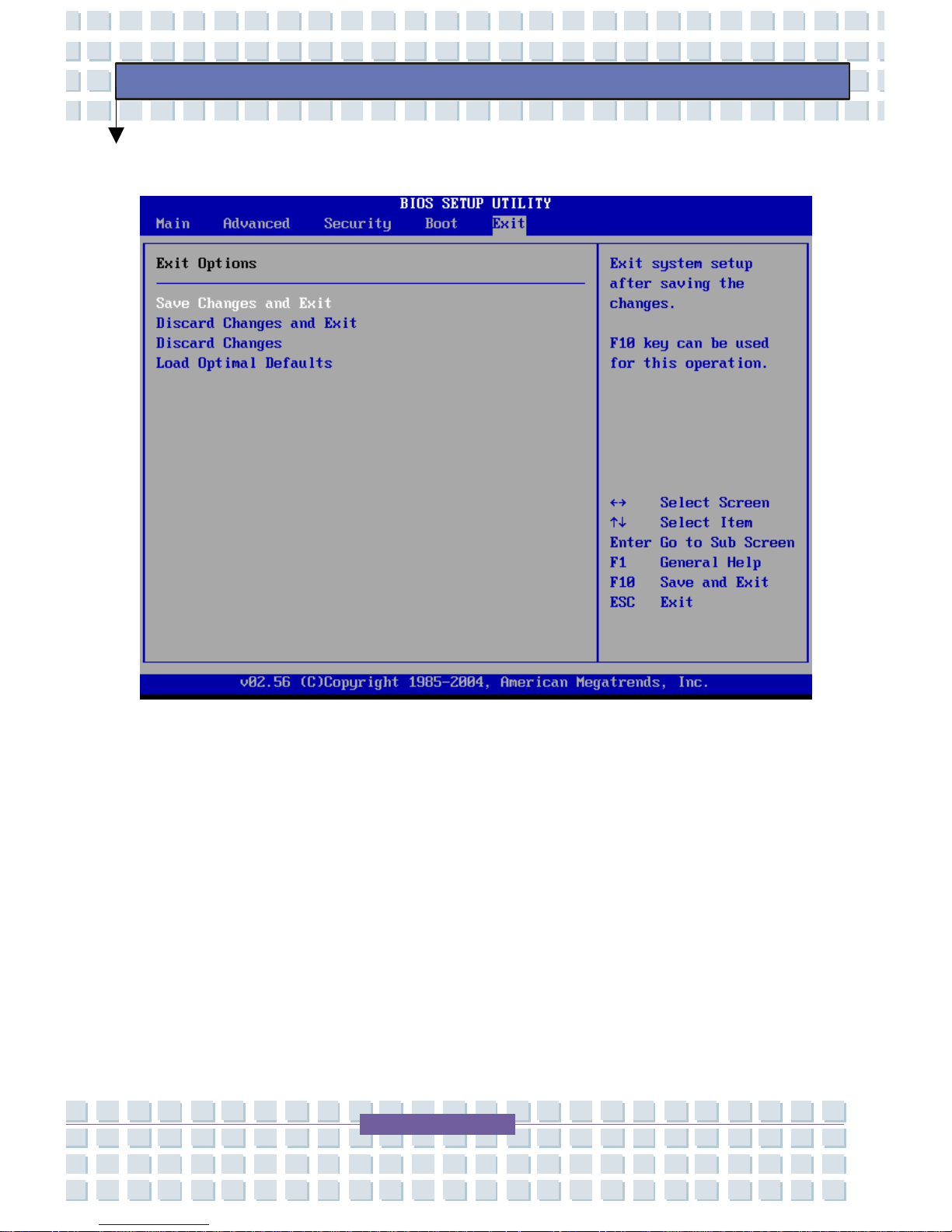
Save Changes and Exit – Save the changes you have
made and exit the utility.
Discard Changes and Exit – Exit the utility without saving
the changes you have made.
Discard Changes – Abandon your changes and reload the
previous configuration before running the utility.
Load Optimal Defaults – Select this item to load the default
settings for optimal system performance.
Page 92
92
Preface
The Computer’s CMOS Battery Care
CMOS (complementary metal-oxide semiconductor) is a semiconductor
chip located on the motherboard, which is powered by a battery
dedicated to supporting the CMOS, “CMOS Battery.” The CMOS stores
information such as the system time and system settings for your
computer.
Caution: The CMOS battery is not rechargeable;
to avoid costly repairs to replace the CMOS
battery you should take the following
p
recautions.
The system requires periodic use in order to ensure the intended
lifespan of the CMOS battery. Ideally, this requires periodic
operation of the system using either the main system battery or
the AC Adapter
Storage of the notebook without use for any period of time is not
recommended.
Page 93

93
Preface
If absolutely necessary, storing the notebook requires
precautions to ensure the intended lifespan of the CMOS battery.
Please take the following precautions:
Do not store your notebook without use for longer than thirty
days.
Remove the main battery from the notebook.
Plug in the AC Adapter and connect to an electrical outlet.
Set the laptop to off.
Page 94
94
Preface
Regulatory Notices
FCC-B Radio Frequency Interference Statement
This equipment has been tested and found to comply with the limits for a
Class B digital device, pursuant to part 15 of the FCC rules. These limits
are designed to provide reasonable protection against harmful
interference in a residential installation. This equipment generates, uses,
and can radiate radio frequency energy and, if not installed and used in
accordance with the instructions, may cause harmful interference to radio
communications. However, there is no guarantee that interference will
not occur in a particular installation. If this equipment does cause harmful
interference to radio or television reception, which can be determined by
turning the equipment off and on, the user is encouraged to try to correct
the interference by one or more of the following measures:
Reorient or relocate the receiving antenna.
Increase the separation between the equipment and receiver.
Connect the equipment into an outlet on a circuit different from
that to which the receiver is connected.
Consult MPC Support for help.
Note: The changes or modifications not expressly
approved by the party responsible for compliance
could void the user’s authority to operate the
equipment.
Page 95

95
Preface
Note: Shield interface cables and AC power cord
must comply with the emission limits.
Wireless LAN Module Statement
This device complies with Part 15 of the FCC Rules. Operation is subject
to the following two conditions:
1. This device may not cause harmful interference.
2. This device must accept any interference received, including
interference that may cause undesired operation.
Any changes or modifications not expressly approved by the
manufacturer could void the user’s authority to operate the equipment.
If necessary, consult your vendor or an experienced radio/television
technician for additional suggestions. The user may find the following
booklet helpful: "Something About Interference." This is available at FCC
local regional offices. MPC is not responsible for any radio or television
interference caused by unauthorized modifications of this equipment or
the substitution or attachment of connecting cables and equipment other
than those specified by our company. The correction will be the
responsibility of the user. Use only shielded data cables with this system.
Page 96

96
Preface
This piece of equipment supports the Wi-Fi wireless LA N security
standard, WPA (Wi-Fi Protected Access) and CCX (Cisco Compatible
eXtensions). To connect to a wireless network consisting of the WPA and
CCX certificates or PROSet may be required depending on the network
settings. For information on the PROSet installation, ask your network
administrator.
Wireless LAN FCC Identifier
PD9WM3945ABG and IC:1000M-3945ABG
Page 97
97
Preface
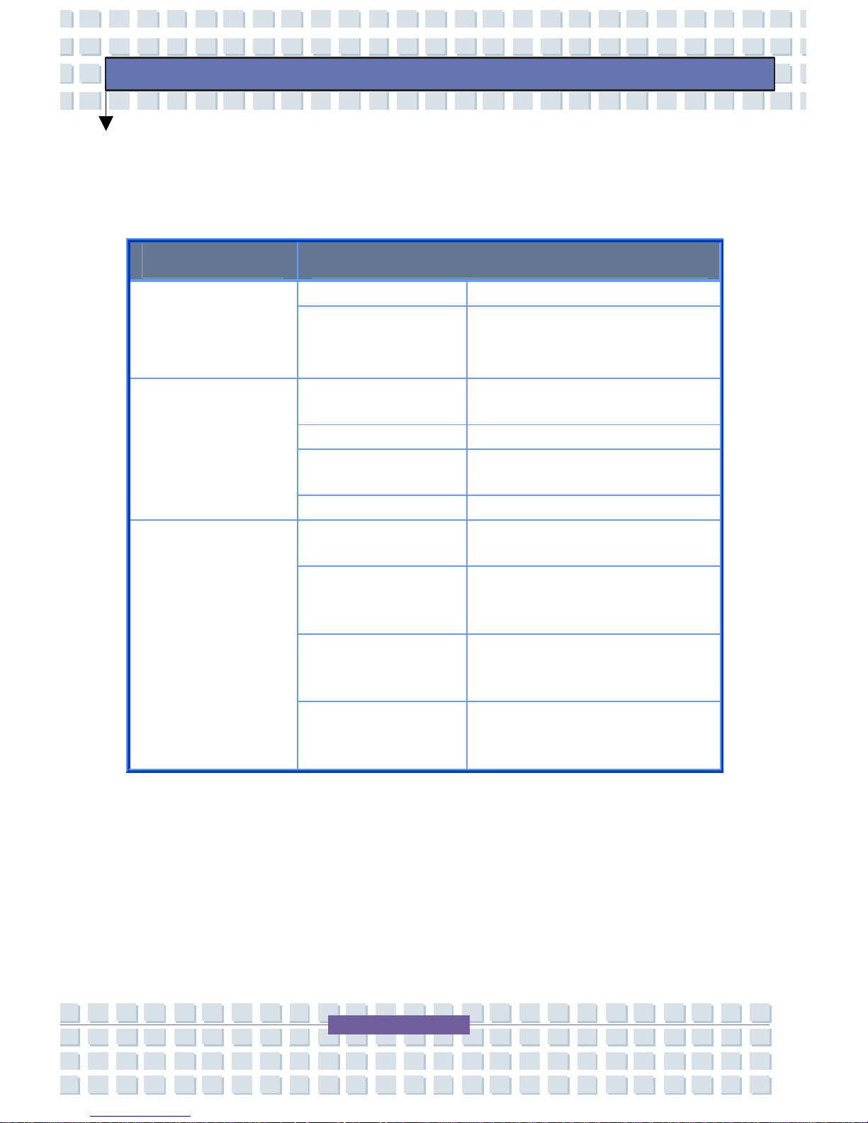
Product Specifications
Intel PRO/Wireless 3945ABG 802.11 Network Connection
Item Detailed Specifications
Dimensions 59.75 x 44.45 mm (wxh)
Physical
Specifications
Operation
Temperature
and Humidity
Temperature: 0°C ~ 70°C
Humidity: less than 85%
Power Saving
Mode
135 mW
Receiving Mode .85 W
Transmission
Mode
1.45 W
Power
Specification
Power 3.3 V
Compatibility IEEE 802.11a, IEEE 802.11b,
IEEE 802.11g
Operating
System
Microsoft Windows® XP and
Windows Vista
™
Business -
NDIS5 Miniport Driver
Media Access
Protocol
CSMA/CA (Collision
Avoidance) with
Acknowledgment (ACK))
Network
Specifications
Security Wired Equivalent Privacy
support (WEP) 64bit/128bit
WPA,* CCX*
• This piece of equipment supports the Wi-Fi wireless LA N security
standard, WPA (Wi-Fi Protected Access) and CCX (Cisco
Compatible eXtensions). To connect to a wireless network consisting
of the WPA and CCX certificates or PROSet may be required
Page 98
98
Preface
depending on the network settings. For information on the PROSet
installation, ask your network administrator.
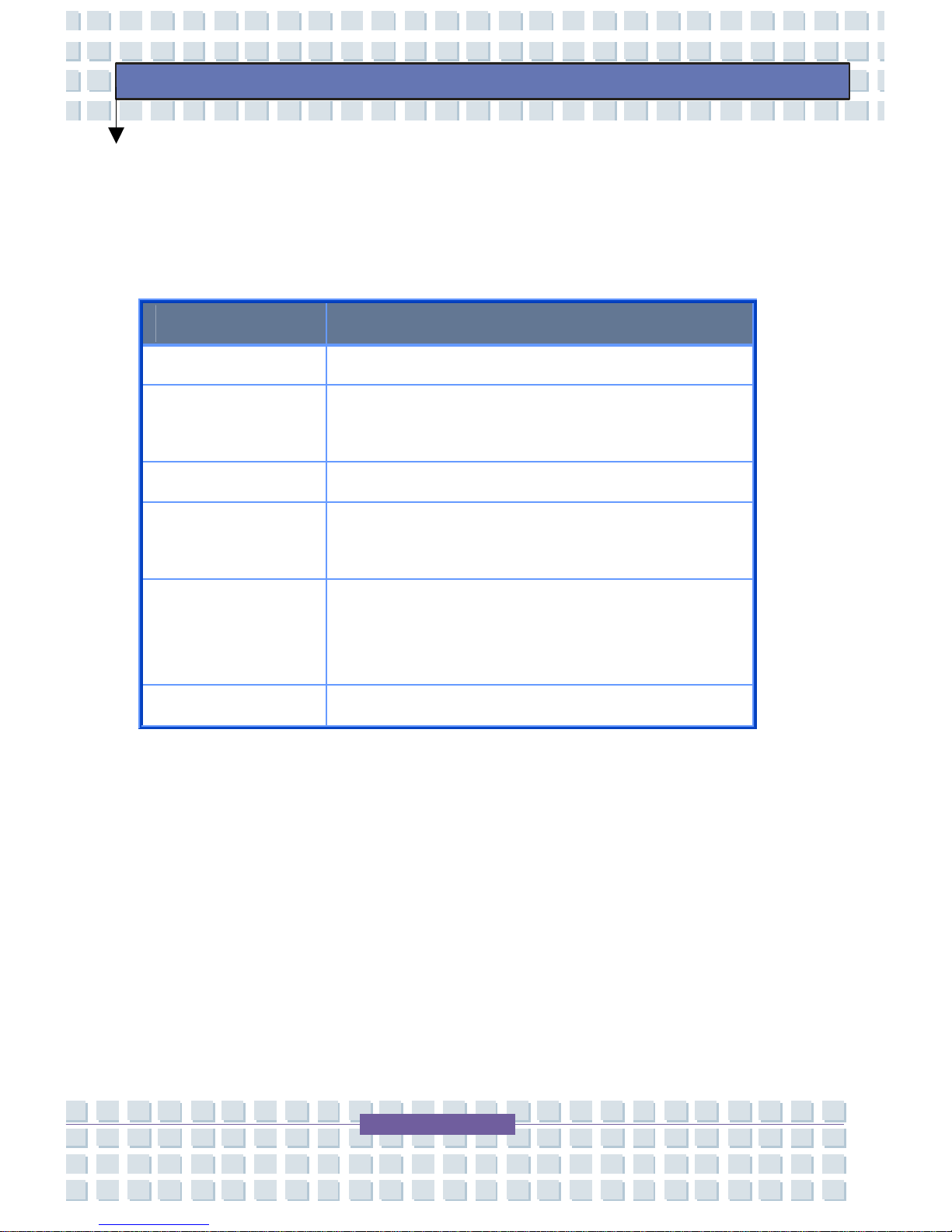
Radio Specifications
Item Detailed Specifications
RF Band 2.4GHz and 5GHz range
Support
Channels
Channels allowed per country.
Device Transceiver
Standard Output
Power
5 mW
Transmission
Rate (Mbps)*
5GHz - 54, 48, 36, 24, 18, 12, 9, 6 Mbps
2.4GHz - 11, 5.5, 2, 1 Mbps
Antenna Type Single Internal Antenna (Main/Aux)
*The transmission rate listed above may differ from the actual
transmission rate. Each mode is supported only when the device is
connected to a compatible Access Point.
Page 99

99
Preface
Electromagnetic Compatibility
USA: FCC Title 47 CFR, Part 15 (Class B)
Canada: ICES-003 (Class B)
FCC Radiation Exposure Statement
The MPC Wireless LAN Mini PCI Card will be installed with an antenna
that is integrated into the LCD screen. The radiated output power of the
MPC Wireless LAN Mini PCI Card is far below the FCC radio frequency
exposure limits. Nevertheless, the MPC Wireless LAN Mini PCI Card
shall be used in such a manner that the potential for human contact
during normal operation is minimized.
In normal operating configuration, the LCD in the upright position, the
distance between the antenna and the user should not be less than
20cm. The antenna used for this transmitter must not be collocated or
operating in conjunction with any other antenna or transmitter. Antenna
used in 5.15-5.25GHz frequency band must be integral antenna that
provide no access to the end user.
Refer to the Regulatory Statements as identified in the documentation
that comes with those products for additional information.
Page 100

100
Preface
FCC Part 68 Statement
This equipment complies with part B of the FCC rules. On the back of
this equipment is a label that contains, among other information, the FCC
registration number and ringer equivalence number (REN) for this
equipment. If requested, this information must be provided to the
telephone company. This equipment uses the following USOC jacks:
RJ11C. An FCC compliant telephone cord and modular plug is provided
with this equipment. This equipment is designed to be connected to the
telephone network or promises wiring using a compatible modular jack
that is Part 68 compliant. See Installation Instructions for details.
The REN is used to determine the quantity of devices that may be
connected to the telephone line. Excessive RENs on the telephone line
may result in the devices not ringing in response to an incoming call. In
most, but not all areas, the sum of RENs should not exceed five. To be
certain of the number of devices that may be connected to a line, as
determined by total RENs, contact the local telephone company to
determine the maximum REN for the calling area.
If the terminal equipment causes harm to the telephone network, the
telephone company will notify you in advance that temporary
discontinuance of service may be required. But if advance notice is not
practical, the telephone company will notify you as soon as possible.
Also, you will be advised of your right to file a complaint with the FCC if
you believe it is necessary.
 Loading...