

Page 1
1
Page 2

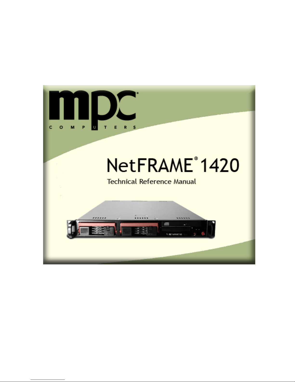
MPC Computers, LLC NetFRAME 1420
Table of Contents
Table of Contents......................................................................................................................... 2
Copyright/Limited Warranty ......................................................................................................... 4
MPC Resources ....................................................................................................................... 5
System Information .................................................................................................................. 6
Manual Conventions................................................................................................................. 6
Printing the Manual .................................................................................................................. 7
Manual Updates ....................................................................................................................... 8
System Safety .......................................................................................................................... 9
Operating Environment .......................................................................................................... 12
Cleaning ................................................................................................................................. 13
Protecting ............................................................................................................................... 13
Features and Specifications ................................................................................................... 14
Server Chassis Views ............................................................................................................15
Server Installation ...................................................................................................................... 18
Unpacking the System ........................................................................................................... 18
Preparing for Setup ................................................................................................................ 19
Server Precautions................................................................................................................. 19
Rack Installation ..................................................................................................................... 20
Safety and Preparation........................................................................................................... 30
Access Panel.......................................................................................................................... 31
Preparation............................................................................................................................. 33
PCI Riser Card ....................................................................................................................... 34
System Fans........................................................................................................................... 34
Drive Bays .............................................................................................................................. 35
Power Supply ......................................................................................................................... 37
Memory................................................................................................................................... 39
Processor and Heatsink ......................................................................................................... 41
System Board Features and Specifications ........................................................................... 46
PC Health Monitoring ............................................................................................................. 48
Jumper Settings ..................................................................................................................... 49
Power Configuration Settings................................................................................................. 56
System Board Installation.......................................................................................................57
Software Installation ............................................................................................................... 58
BIOS Setup ................................................................................................................................ 62
Changing the Configuration Data........................................................................................... 62
2
Page 3

MPC Computers, LLC NetFRAME 1420
Running Setup........................................................................................................................ 62
Main Setup ............................................................................................................................. 63
Advanced Setup ..................................................................................................................... 66
Security................................................................................................................................... 74
Boot ........................................................................................................................................ 75
Exit.......................................................................................................................................... 76
System Board Problems......................................................................................................... 77
BIOS POST Messages........................................................................................................... 78
Diagnostic Testing Preparation .............................................................................................. 84
Initial System Startup Problems ............................................................................................. 84
New Application Software Problems ...................................................................................... 85
Problems After the System Has Been Running ..................................................................... 85
FAQs ...................................................................................................................................... 86
Specific Problems................................................................................................................... 86
Service and Support .................................................................................................................. 90
MPC Technical Support ......................................................................................................... 90
Regulatory Information............................................................................................................... 91
Product Regulatory Compliance............................................................................................. 91
Index .............................................................................................................................................. 93
Page 4

MPC Computers, LLC NetFRAME 1420
Copyright/Limited Warranty
Copyright 2005 MPC Computers, LLC. All rights reserved. The information in this document is
subject to change without prior notice in order to improve reliability, design, and function and does
not represent a commitment on the part of the manufacturer. In no event will the manufacturer or
seller of an MPC product be liable for direct, indirect, special, incidental, or consequential
damages arising out of the use or inability to use the product or documentation, even if advised of
the possibility of such damages. Except as stated in the applicable MPC Computers, LLC limited
warranty, MPC and its affiliates, by this manual, make no other express warranties. THE
IMPLIED WARRANTY OF MERCHANTABILITY AND THE IMPLIED WARRANTY OF FITNESS
FOR A PARTICULAR PURPOSE ARE HEREBY DISCLAIMED. IF THESE LIMITATIONS DO
NOT APPLY TO YOU, THEN ALL IMPLIED WARRANTIES AND CONDITIONS OF
MERCHANTABILITY AND FITNESS FOR A PARTICULAR PURPOSE ARE LIMITED IN TIME
TO THE TERM OF THE LIMITED WARRANTY PERIOD REFLECTED ON YOUR PACKING
SLIP OR INVOICE. NO WARRANTIES, WHETHER EXPRESS OR IMPLIED, WILL APPLY
AFTER THE LIMITED WARRANTY PERIOD HAS EXPIRED. This document contains proprietary
information that is protected by copyright. All rights are reserved. No part of this document may
be photocopied, reproduced, or translated to another language without the prior written consent
of:
MPC Computers, LLC
906 E. Karcher Road
Nampa, Idaho 83687
Trademark Notice
Windows, Windows 2000, MS-DOS, and Microsoft are registered trademarks of Microsoft
Corporation. Pentium and MMX are trademarks or registered trademarks of Intel Corporation.
Other product names mentioned herein are used for identification purposes only and may be
trademarks and/or registered trademarks of their respective companies.
Limitation of Liability
While reasonable efforts have been made to ensure the accuracy of this manual, the
manufacturer and seller assume no liability resulting from errors or omissions in this manual or
from the use of the information contained herein.
Notices
No part of this publication may be reproduced, stored in a retrieval system, or transmitted, in any
form or by any means (mechanical photocopying, recording or otherwise) without the prior written
permission of the manufacturer. The information within this manual is subject to change without
notice.
The manufacturer shall not be held liable for technical or editorial errors or omissions contained
herein; nor for incidental or consequential damages resulting from the furnishing, performance, or
use of this material.
Life Support and Nuclear Facilities
Products sold by MPC are not authorized for use as critical components in medical devices or
systems or in nuclear facilities without the express written approval of the Chief Executive Officer
of MPC.
EMA001076-00, KDA, 10-31-2005
4
Page 5
MPC Computers, LLC NetFRAME 1420
Welcome
Congratulations on the purchase of your MPC NetFRAME® 1420 server.
The following sections contain more information about your server and this manual:
MPC Resources
System Information
Manual Conventions
Printing the Manual
Manual Updates
MPC Resources
MPC provides several resources to assist you with using your new storage solution.
Further Reading
It is recommended that you read all documentation, in addition to this manual, related to any
software or hardware supplied with your storage solution.
For More Information
For the latest information about your storage solution and about MPC services, please visit the
MPC Web site at www.mpccorp.com.
Manual Comments
If you would like to comment or ask questions about the manual, please contact us at
[email protected].
Service and Support
Service and Support Tools
Main Support Site
Knowledge Base
Contacting Support
http://support.mpccorp.com
http://primus.mpccorp.com/mknowledge/
Support Phone Number: (800) 249-1178
Page 6

MPC Computers, LLC NetFRAME 1420
System Information
If you require technical support in the future, the following information will help an MPC support
technician locate the specifications for your server and aid in returning it to normal operation.
Model Names and Manual Number
Model Name
Manual Number
NetFRAME® 1420
5015M-T
EMA001076-00
Manual Conventions
The following conventions are used throughout this manual.
Note: Important information concerning the operation of your server.
Caution: Failure to follow directions could result in loss of data or damage to
equipment. Failure to heed these cautions could negate the user warranty.
Warning: Failure to follow directions will result in loss of data or damage to
equipment and/or could result in physical harm. Failure to heed these
warnings could negate the user warranty.
Special Text
The text in this guide is formatted to highlight unique information or instructions. Review the
following examples of special text used throughout this manual:
Screen (window) names, functions, or anything that appears on the screen is formatted in
bold. For example: Click OK, the Standards screen, the Edit menu.
Keyboard strokes are indicated by brackets. For example: Press [Enter], use the [Alt] key.
When keys should be held down simultaneously, they are separated by the + sign. For
example: Press [Ctrl+Alt+Delete]. When keys should be pressed sequentially, they will be
in individual brackets without the + sign. For example: Press [1][Enter]. The [1] key
should be pressed first, and then the [Enter] key should be pressed.
Screen messages are indicated by quotes. For example: The message "Enter your
username and password" will appear.
Anything that you need to type will appear in italics. For example: Enter the word
password.
6
Page 7
MPC Computers, LLC NetFRAME 1420
Printing the Manual
This system manual may be printed as a PDF document or directly from this Online Help version.
The instructions below explain how to print this system manual.
Printing the PDF Manual
Printing from Online Help
Printing the PDF Manual
A PDF version of this manual can be found at the following locations:
NetFRAME 1420 Drivers and Documentation CD: Install the CD and click on the
Technical Reference Manual link for further instructions.
System Hard Drive: Search for the file name: NetFRAME1420.pdf.
The MPC Support Web site: http://support.mpccorp.com. See Manual Updates for
instructions.
Note: The links contained throughout this manual are only operative in the online
help version of the manual.
Printing from Online Help
Printing the Entire Manual
To print the entire manual, complete the following steps:
1. Click the book titled NetFRAME
of the Contents tab.
2. Click the Print button located on the menu bar.
3. When the Print Topics dialog box appears, select Print the selected heading and all
subtopics.
4. Click OK.
5. When the Print dialog box appears, make the appropriate selections, and print the
manual.
Note: The Print dialog box may take a few seconds to appear. Also, the Print
dialog box may minimize to the taskbar, so check the taskbar if the dialog bo x does
not appear.
Printing Topics or Parts of the Manual
To print a specific topic or part of the manual, complete the following steps:
1. Click the book title or topic title that you want to print.
®
1420 Technical Reference Manual located at the top
2. Click the Print button located on the menu bar.
3. When the Print Topics dialog box appears, do one of the following:
Select Print the selected topic if you selected a topic title.
Select Print the selected heading and all subtopics if you selected a book title.
Page 8

MPC Computers, LLC NetFRAME 1420
4. Click OK.
5. When the Print dialog box appears, make the appropriate selections, and print the
manual topic(s).
Note: The Print dialog box may take a few seconds to appear. Also, the Print
dialog box may minimize to the taskbar, so check the taskbar if the dialog bo x does
not appear.
Manual Updates
Periodically, updates are made to our manuals. You can access these updated manuals on the
MPC Support site at http://support.mpccorp.com. Please note that not all of the manual updates
will be applicable to your system. Complete the following steps to search for manual updates:
1. Go to the MPC Support Web site at http://support.mpccorp.com.
2. Click the Platforms link.
3. Click the Components link.
4. Click the Manuals link.
5. Search for the following part number: EMA001076-XX.
If the manual has been updated, the XX number will be greater than -00, such as -01, 02, and -03. If you find a manual update, download the manual by clicking on the link and
following the on-screen instructions.
Note: A PDF version of the manual is also available for printing from the MPC
Support Web site.
8
Page 9
MPC Computers, LLC NetFRAME 1420
System Safety and Care
Your MPC server has been manufactured to the highest quality standards. With proper care, it
should provide years of trouble-free service. The following sections provide information that will
help ensure your system has the longest life possible:
System Safety
Operating Environment
Cleaning
Protecting
System Safety
The following instructions pertain to the risk of fire, electric shock, or bodily injury. Please read all
of these instructions carefully and save them for later use.
Warning: Keep all packing materials away from children.
Follow all the instructions and warnings marked on this product or included in this manual.
Electrical Safety Precautions
Use the exact type of power cords as required.
Be sure to use power cord(s) that came with safety certifications.
The power cord(s) must be compliant with the AC voltage requirements in your region.
The power cord plug cap must have an electrical current rating that is at least 125% of
the electrical current rating of this product.
Plug the Power cord(s) into a socket that is properly grounded before turning on the
power.
Be aware of the locations of the power on/off switch on the chassis as well as the room's
emergency power-off switch, disconnection switch, or electrical outlet. If an electrical
accident occurs, you can then quickly remove power from the system.
Do not work alone when working with high voltage components.
Power should always be disconnected from the system when removing or installing main
system components, such as the system board, memory modules, and IDE/floppy drives.
When disconnecting power, first power down using the operating system and then unplug
all of the power supply units in the system.
To avoid making a complete circuit, which will cause electric shock, use only one hand
when working with powered-on electrical equipment.
Use extreme caution when using metal tools, which can easily damage any electrical
components or circuit boards.
Do not use mats designed to decrease static electrical discharge as protection from
electrical shock. Instead, use rubber mats that have been specifically designed as
electrical insulators.
Page 10
MPC Computers, LLC NetFRAME 1420
The power supply cords must include a grounding plug and must be plugged into
grounded electrical outlets. Follow all the instructions and warnings marked on this
product or included in this manual.
MPC recommends storing and using this product on a surface or rack specifically
designed for that purpose. Do not use this product on an unstable surface. The product
might fall, causing serious damage.
Slots and openings in the server are provided for ventilation. To ensure the reliable
operation of your product and to protect it from overheating, these openings must not be
blocked or covered. Do not use this product on a sofa, rug, or other soft surface. This
product must never be placed near or over a radiator or heat register. This product must
not be placed in a built-in enclosure of any kind unless proper ventilation is provided.
Never push objects of any kind into the product through the cabinet openings. They may
touch dangerous voltage points or short out parts — possibly resulting in an electric
shock or a fire hazard.
Never spill liquid of any kind on the product.
This product must only be connected to the AC power source as indicated on the power
supply information label. If you are not sure of the type of AC power available, ask the
local power company. Only connect this product to a power outlet that matches the power
requirements of this product.
Do not allow anything to rest on the power cord. Do not place this product where people
might walk on the cord.
If you use an extension cord with this product, make sure that the total amperage rating
of all equipment plugged into it does not exceed the amperage rating of the extension
cord. Ensure that all the products plugged into the main AC power outlet do not exceed
15 amps.
Unplug the product from the main electrical AC power outlet before cleaning. Do not use
liquid or aerosol cleaning solvents directly on the product. Use a damp cloth for cleaning
the exterior surfaces.
Do not use this product near standing bodies of water or in humid environments.
Unplug this product from the main AC power outlet and call for service if any of the
following conditions occur:
The power cord or plug is damaged or frayed.
Liquid has been spilled into the product.
The product has been exposed to rain or corrosive liquids.
The product has been dropped, or the case has been damaged.
The product’s performance changes, indicating a need for service.
Warning: Do NOT open the power supply cover; hazardous voltage s are
present. There are no user-serviceable components inside.
Warning: There is a danger of explosion if the onboard battery is installed
upside down, which would reverse its polarity. This battery must be
replaced only with the same or an equivalent type recommended by the
manufacturer. Dispose of used batteries according to the manufacturer's
instructions.
Warning: This server may have come equipped with a CD-ROM drive. To
prevent direct exposure to the laser beam and hazardous radiation, do not
open the enclosure or use the unit in any unconventional way.
10
Page 11

MPC Computers, LLC NetFRAME 1420
Operating Precaution
To ensure proper cooling and to avoid damage that is not covered under warranty, make sure
that the chassis cover is in place when the server is operating.
General Safety Precautions
Keep the area around the server clean and free of clutter.
Place the chassis top cover and any system components that have been removed away
from the system or on a table so that they won't accidentally be stepped on.
While working on the system, do not wear loose clothing such as neckties and
unbuttoned shirt sleeves, which can come into contact with electrical circuits or be pulled
into a cooling fan.
Remove any jewelry or metal objects from your body. These are excellent conductors
that can create short circuits and harm you if they come into contact with printed circuit
boards or areas where power is present.
After ensuring that all connections have been made, close the system and secure it to the
rack unit with the retention screws.
To avoid injuries to the back, be sure to use your leg muscles, keep your back straight,
and bend your knees, when lifting the system.
After removing the components or chassis covers from the system, place them on a table
for safeguard.
Be sure to remove any jewelry or metal objects before working on the chassis to avoid
short circuits should these objects come into contact with power circuits.
After accessing the interior of the chassis, be sure to close the chassis with chassis
covers and secure the chassis to the racks with screws.
Electrostatic Discharge (ESD) Precautions
Before working inside your server, it is important to know how to protect it from Electrostatic
Discharge (ESD) damage.
Caution: Modules are Electrostatic Sensitive. A small electrostatic discharge
(ESD) can damage server components. An ESD-damaged module or PCI card
might not fail immediately, but over time it could become worse, possibly
causing an intermittent problem. Be very careful to handle the module or PCI
card ONLY by the edges. DO NOT touch the gold/silver edge-connectors or
any of the components on the system board. Leave the new module or PCI
card in the antistatic bag until you are ready to install it. Place the original
module or PCI card in an antistatic bag immediately after removing it from
the system.
Page 12
MPC Computers, LLC NetFRAME 1420
Electrostatic discharge (ESD) is generated by two objects with different electrical charges coming
into contact with each other. An electrical discharge is created to neutralize this difference, which
can damage electronic components and printed circuit boards. The following measures are
generally sufficient to neutralize this difference and protect your equipment from ESD:
Use a grounded wrist strap designed to prevent static discharge.
Keep all components and printed circuit boards (PCBs) in their antistatic bags until ready
for use.
Touch a grounded metal object before removing the board from the antistatic bag.
Do not let components or PCBs come into contact with your clothing, which may retain a
charge even if you are wearing a wrist strap.
Handle a board by its edges only; do not touch its components, peripheral chips, memory
modules, or contacts.
When handling chips or modules, avoid touching their pins.
Put the system board and peripherals back into their antistatic bags when not in use.
For grounding purposes, make sure your computer chassis provides excellent
conductivity between the power supply, the case, the mounting fasteners, and the system
board.
Operating Environment
Temperature Concerns
The system specifications ensure the server will operate in ambient (room) temperatures up to
95°F (35°C). It is important to keep your server out of direct sunlight and away from other heat
sources (such as lamps and heating vents). Make sure the fan vents on your chassis are not
blocked.
If room temperature consistently exceeds 95°F (35°C), move the server to a cooler location to
keep it under the maximum temperature.
Moisture and Humidity Concerns
While your server will generally run better in cooler environments, there are server components
that are adversely affected by cold temperatures.
Caution: If your server arrives in cold weather, do not apply power to it or the
monitor until they come to room temperature.
Exposing the server to cold temperatures can produce condensation that can damage individual
components or destroy your system.
Warning: Never expose the server to moisture. Moisture exposure can lead
to an electrical shock or a fire hazard. Operating the server in areas with high
humidity can damage system components.
12
Page 13
MPC Computers, LLC NetFRAME 1420
Temperature and Humidity Operational Levels
Temperature
Humidity
Operational (Powered On) Non-Operational (Powered Off)
50°F to 95°F (10°C to 35°C) -40°F to 158°F (-40°C to 70°C)
up to 90% RH Non-condensing up to 95% RH Non-condensing
Other Environmental Concerns
High levels of dust, dirt, or smoke can also damage your server. Place the server in an area with
good ventilation. Periodically check the server's case, side, and bottom to ensure that dust or dirt
is not accumulating on the vents.
Shock, Vibration, and Altitude Operational Levels
Shock
Altitude
Operational (Powered On) Non-Operational (Powered Off)
2 G, 11 ms, half-sine 50 G, 11 ms, half-sine
up to 10,000 ft up to 10,000 ft
Cleaning
If the case becomes dirty through constant use or handling, use only a damp, dust-free cloth for
cleaning. Do not use abrasives or solvents as these may mar or scratch the case.
Cleaning kits designed to clean floppy disk drives, DVD drives, and CD-ROM drives are available
at most computer stores and should be used periodically.
Protecting
To prevent normal electrical problems such as spikes or surges, install a high-quality power surge
protector between the wall outlet and all of the system's connected components. If even one
component is not connected to the surge protector, the entire system could be at risk. You should
note that some power strips are not surge protectors but simply extension cords.
If your local area is subject to frequent electric power failures, MPC recommends attaching an
uninterruptible power supply (UPS) to the server and monitor. The UPS should be connected to
an AC generator. A UPS will provide time to save all data files and properly turn off the system.
Caution: If a storm enters your area, completely unplug the entire system
from all electrical sources, including telephone lines. Electricity from
lightning can travel in on any line and destroy all connected components.
Transporting
Always shut the server off before moving it. Any sudden jar or shock may permanently damage
the hard disk. Hard disks are more resistant to shock if they are properly shut down before being
moved. If you are transporting the server over long distances, completely repackage it in its
original packing material. If the original packaging is unavailable, pack the server with as much
padding as possible to ensure that the components are not exposed to excessive vibration or
shock.
Page 14

MPC Computers, LLC NetFRAME 1420
System Features
The following sections will help you locate and identify the components and connectors on your
server.
Features and Specifications
Server Chassis Views
System Interface
Features and Specifications
The NetFRAME® 1420 is a scaleable 1U rackmount server platform. The following is a general
outline of the system features and specifications.
Features and Specifications
Feature Specifications
CPU
Memory
Chipset
Expansion
Slots
BIOS
System Board
Single Intel® Celeron® D, or Intel® Pentium® 4, or Intel®
Pentium® D Processor (LGA 775 Socket)
Four DIMM sockets supporting up to 8GB ECC DDR2 SDRAM
Intel E7230 chipset
One universal PCI-X 133 MHz/PCI-Express x8 slot and one 32-
bit, 33 MHz (5V) PCI slot. The PCI-X 133 MHz slot is available for
use with the riser card included with the system (the PCI-Express
x8 slot is available for use with the optional CSE-RR1U-ELi riser
card).
8 Mb Phoenix® Flash ROM
Form Factor: ATX
Dimensions: 12 x 9.6 in (305 x 244 mm)
SATA
Controller
14
Intel ICH7R on-chip controller for 4-port SATA subsystem (RAID
0, 1, 5 and 10 supported)
Page 15

MPC Computers, LLC NetFRAME 1420
SATA/IDE
Drive Bays
Network
Interface
Peripheral
Drive Bays
Chassis
Dimensions
and Weight
Up to 2 hot-swap SATA hard drives; 1 Slimline CD-ROM drive, 1
floppy drive.
Integrated Dual Gigabit Ethernet
One (1) floppy drive
One (1) slim CD-ROM drive
Form Factor: 1U rackmount
Dimensions: (WxHxD) 16.8 x 1.7 x 22.6 in. (426 x 43 x 574 mm)
Weight: Approximately 45lbs (shipping weight)
Server Chassis Views
The following sections will help you locate and identify the components and connectors on your
server.
Front Panel Views
Back Panel View
Control Panel Buttons and LEDs
Page 16
MPC Computers, LLC NetFRAME 1420
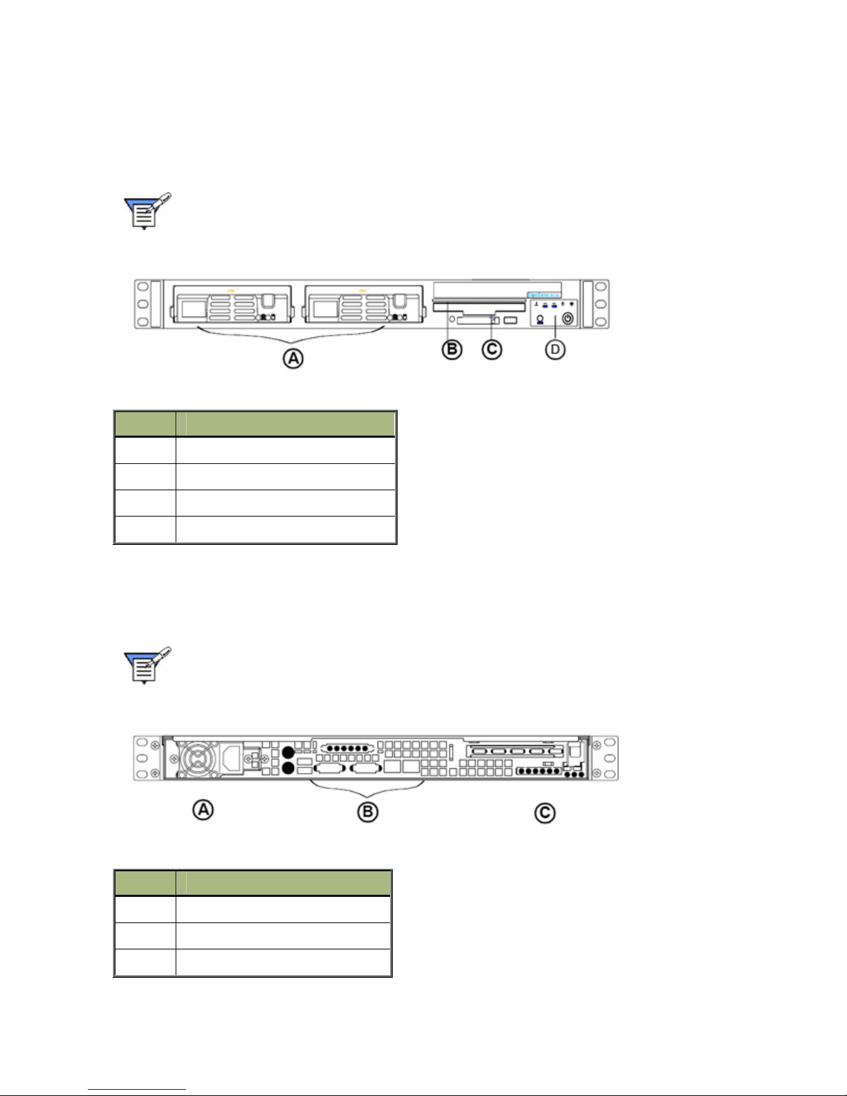
Front Panel View
The figure below illustrates the features on the front panel of your NetFRAME® 1420 server
chassis.
Note: The appearance, location, and existence of the components
mentioned may vary by model.
Front Panel Layout
Front Panel I/O Definitions
Letter Definition
A 1" Hot-swap SATA Drive Bay (2)
B Slim CDROM (1)
C Floppy (1)
D Front Control Panel
Back Panel View
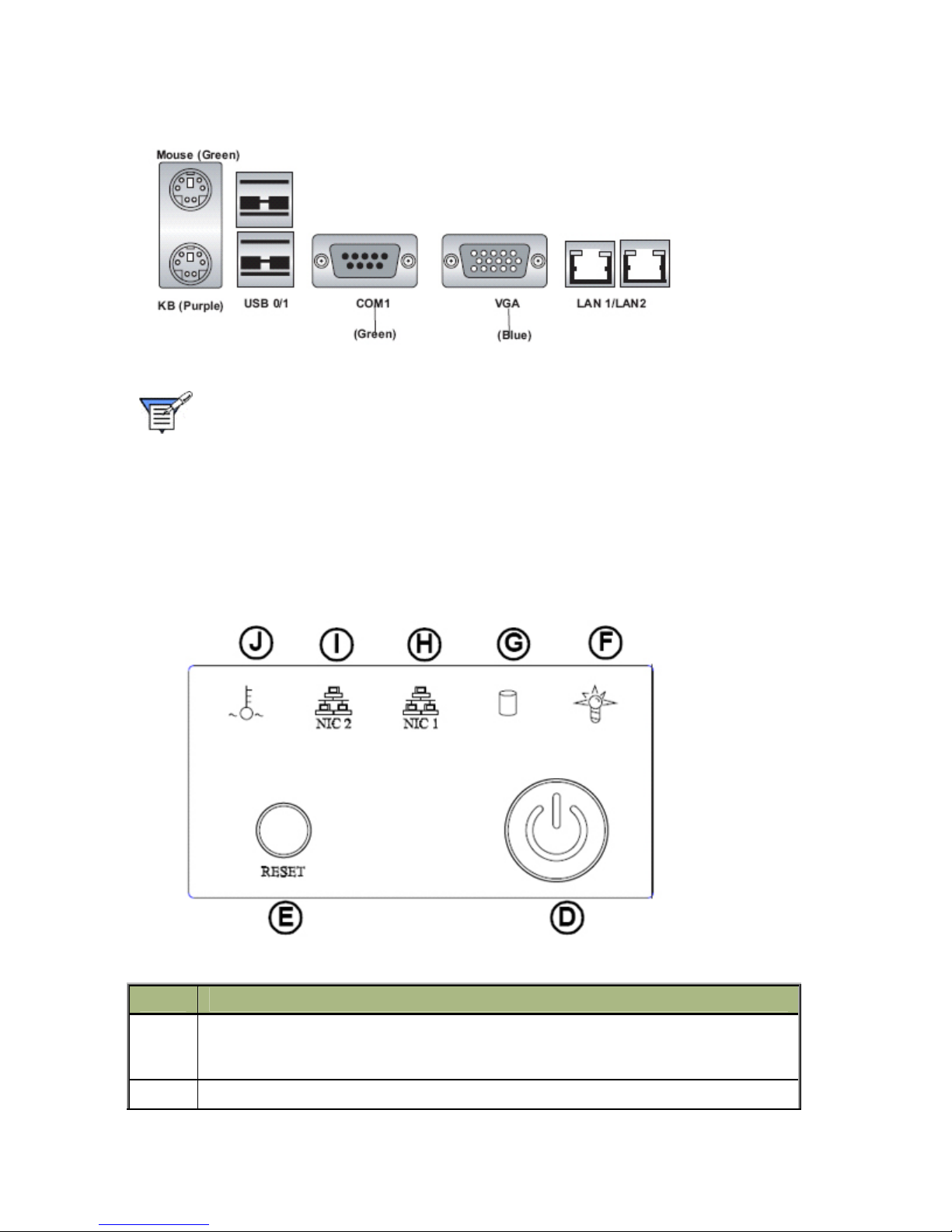
The figure below illustrates the connectors on the back panel of your NetFRAME® 1420 server
chassis.
Note: The appearance, location, and existence of the components mentioned may
vary by model.
Back Panel View
Back Panel Definitions
Letter Definition
A Power Supply Module
B Back Panel I/O Ports
C Full size PCI Expansion Slot (1)
16
Page 17
MPC Computers, LLC NetFRAME 1420
Back Panel I/O
Note: The actual I/O Configuration of your system might be different from the one
shown above.
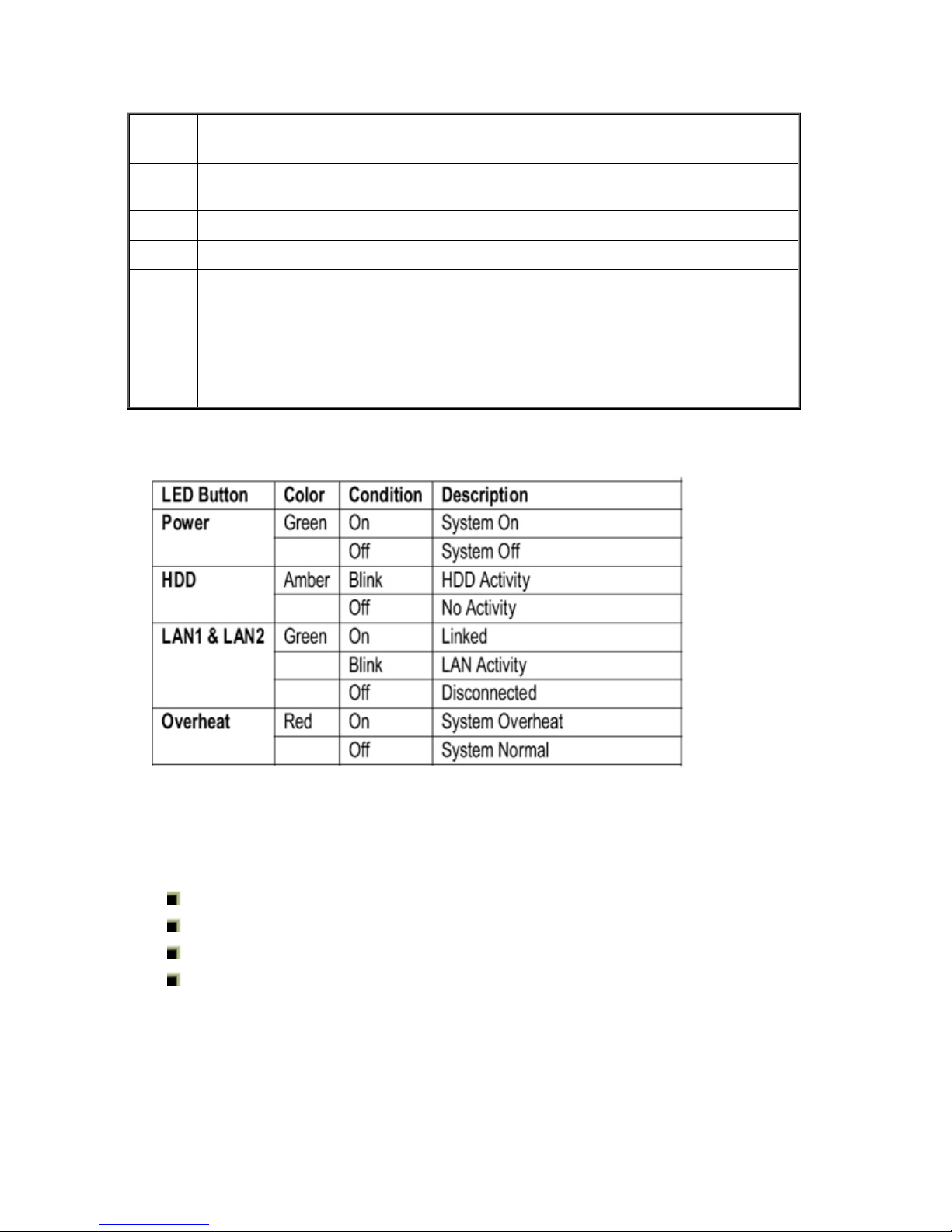
Control Panel Buttons and LEDs
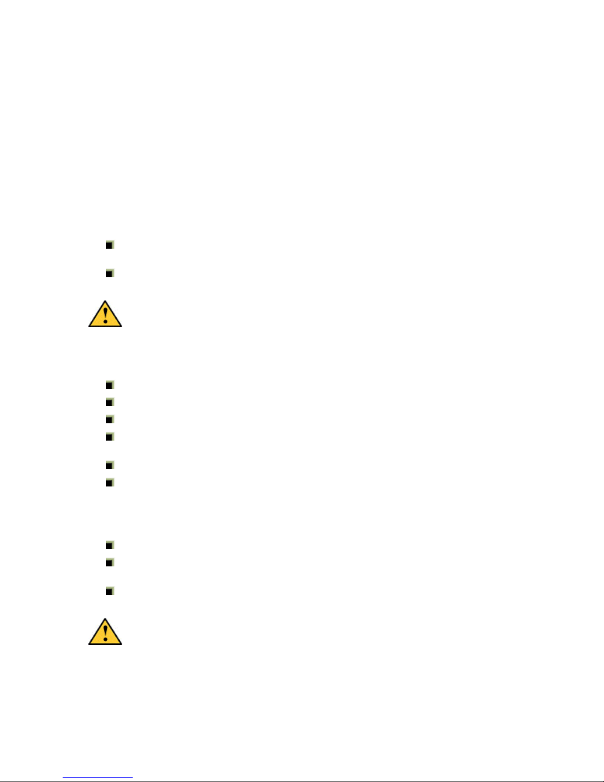
The control panel located on the front of the chassis has buttons and LEDs. LEDs indicate power
on, network activity, hard disk drive activity and overheat/fan fail conditions. The control panel
also includes a main power button and a system reset button.
Control Panel Buttons and LEDs
LED Button Definitions
Letter Description
D Power Button: This is the main power switch, which is used to apply or turn off the
main system power. Turning off system power with this button removes the main
power but keeps standby power supplied to the system.
E Reset Button: The reset switch reboots the system.
Page 18
MPC Computers, LLC NetFRAME 1420
F Power Indicator: Indicates power is being supplied to the system's power supply
units. This LED should normally be illuminated when the system is operating.
G HDD Activity: Channel activity for all HDDs. This light indicates CD-ROM and SATA
drive activity when flashing.
H NIC1: Indicates network activity on JLAN1 when flashing.
I NIC2: Indicates network activity on JLAN2 when flashing .
J Overheat/Fan Fail: When this LED flashes, it indicates a fan failure. When on
continuously it indicates an overheat condition, which may be caused by cables
obstructing the airflow in the system or the ambient room temperature being too
warm. Check the routing of the cables and make sure all fans are present and
operating normally. You should also check to make sure that the chassis covers are
installed. Finally, verify that the heatsinks are installed properly. This LED will
remain flashing or on as long as the indicated condition exists.
LED Control Panel LED Button Descriptions
Server Installation
This section provides a quick setup checklist to get your system up and running. Follow the steps
in the following sections in order to get the system operational in a minimal amount of time.
Unpacking the System
Preparing for Setup
Server Precautions
Rack Installation
Unpacking the System
Inspect the box the system was shipped in and note if it was damaged in any way. If the server
itself shows damage, file a damage claim with the carrier who delivered it.
18
Page 19
MPC Computers, LLC NetFRAME 1420
Decide on a suitable location for the rack unit that will hold the system. It should be situated in a
clean, dust-free area that is well ventilated. Avoid areas where heat, electrical noise, and
electromagnetic fields are generated. Place it near a grounded power outlet. Read the Server
Precautions and Rack Precautions.
Preparing for Setup
The box the system was shipped in should include two sets of rail assemblies, two rail mounting
brackets, and the mounting screws. Follow the steps in order to complete the installation process
in a minimal amount of time. Please read this section in its entirety before you begin the
installation procedure.
Choosing a Setup Location
Leave enough clearance in front of the rack to open the front door completely (~25
inches).
Leave approximately 30 inches of clearance in the back of the rack for sufficient airflow
and ease in servicing.
Caution: Please read all Rack and Server precautions before beginning
installation.
Server Precautions
Review the electrical and general safety precautions.
Determine the placement of each component in the rack before you install the rails.
Install the heaviest server components on the bottom of the rack first, and then work up.
Use a regulating uninterruptible power supply (UPS) to protect the server from power
surges, voltage spikes and to keep your system operating in case of a power failure.
Allow the power supply units to cool before touching them.
Always keep the rack's front door and all panels and components on the servers closed
when not servicing to maintain proper cooling.
Electrostatic Discharge (ESD) Cautions
Leave the module in the antistatic bag until you are ready to install it.
The system should be opened on an ESD-safe workbench, and the technician should
wear an ESD-safe smock with grounding wrist and foot straps.
Keep DIMMs in the antistatic bag while transporting, especially when crossing carpet.
Antistatic wrist straps with clip-on ends are available commercially.
Caution: The system board conforms to the new PCI 2.2 specification. This
requires 3.3v standby for all PCI slots, DIMM banks, and PS/2 outputs
(KB/PS/2 Mouse). Always remember to unplug the AC power cord before
adding any PCI cards, memory, or plugging/unplugging the keyboard or
mouse. Otherwise, the system may automatically power up when adding the
component. This could damage the system board or the component you are
adding and is not covered under warranty.
Page 20
MPC Computers, LLC NetFRAME 1420
Safety: Before You Remove the Access Panel
Before removing the access panel for any reason, observe these safety guidelines.
Turn off all peripheral devices connected to the server.
Turn off the server by pressing the power button on the front of the chassis. Then unplug
the AC power cord on the back of the chassis.
Disconnect all peripheral cables and all telecommunication lines connected to the I/O
connectors or ports on the back of the chassis.
Warning: The power button on the front panel DOES NOT turn off the AC
power. To disconnect power from the server, you must unplug the AC power
cord from the wall outlet or the chassis.
Warning: Hazardous electrical conditions may be present on power,
telephone, and communication cables. Turn off the server and disconnect
the power cords, telecommunications systems, networks, and modems
attached to the server before opening the server case. Otherwise, personal
injury or equipment damage can result.
Warning: Hazardous voltage, current, and energy levels are present inside
the power supply. There are no user-serviceable parts inside the po wer
supply; servicing should be performed by technically qualified personnel.
Caution: For proper cooling and airflow, always install the access panel
before turning the server on. Operating the server without the access pan el
in place can damage system parts.
Rack Installation
This section provides information on installing the system into a rack unit. There are a variety of
rack units on the market, which may mean the assembly procedure will differ slightly. The
following is a guideline for installing the system into a rack using the rack rails provided with the
system. Refer to the installation instructions that came with the rack unit you are using.
Rack Installation Safety
Rack Precautions
Installing Inner Rails
Installing Outer Rails
Open Rack Installation
Rack Installation Safety
Your NetFRAME® 1420 chassis comes equipped with a rack mount kit that can be configured for
front-mount, mid-mount, or 4-post racks. An optional slide rail kit may be purchased separately.
Each kit contains instructions for installation into a rack or cabinet. Read the following instructions
prior to installing your server in a rack.
20
Page 21
MPC Computers, LLC NetFRAME 1420
Caution: Carefully read all precautions and instructions before installation.
Equipment Rack Precautions
The equipment rack must be anchored to an unmovable support to prevent it from falling
over when one or more servers are extended in front of it on slide assemblies. The
equipment rack must be installed according to the manufacturer's instructions. You must
also consider the weight of any other device installed in the rack.
You are responsible for installing an AC power disconnect for the entire rack unit. This
main disconnect must be readily accessible, and it must be labeled as controlling power
to the entire unit, not just to the server(s).
To avoid the potential for an electrical shock hazard, you must include a third wire safety
grounding conductor with the rack installation. If server power cords are plugged into AC
outlets that are part of the rack, then you must provide proper grounding for the rack
itself. If server power cords are plugged into wall AC outlets, the safety grounding
conductor in each power cord provides proper grounding only for the server. You must
provide additional, proper grounding for the rack and other devices installed in it.
The server is designed for an AC line voltage source with up to 20 amperes of over
current protection. If the power system for the equipment rack is installed on a branch
circuit with more than 20 amperes of protection, you must provide supplemental
protection for the server. If more than one server is installed in the rack, the power source
for each server must be from a separate branch circuit.
Temperature: The operating temperature of the server, when installed in an equipment
rack, must not go below 10° C (50° F) or rise above 35° C (95° F). Extreme fluctuations in
temperature can cause a variety of problems in your server.
The equipment rack must provide sufficient airflow to the front of the server to maintain
proper cooling.
Rack Precautions
Caution: Carefully read all precautions and instructions before installation.
Ensure that the leveling jacks on the bottom of the rack are fully extended to the floor with
the full weight of the rack resting on them.
In a single rack installation, stabilizers should be attached to the rack.
In multiple rack installations, the racks should be coupled together.
Make sure the rack is stable before extending a component from the rack.
Extend only one component at a time - extending two or more simultaneously may cause
the rack to become unstable.
The equipment rack must be anchored to an unmovable support to prevent it from falling
over when one or more servers are extended in front of it on slide assemblies. The
equipment rack must be installed according to the manufacturer's instructions. You must
also consider the weight of any other device installed in the rack.
Page 22

MPC Computers, LLC NetFRAME 1420
You are responsible for installing an AC power disconnect for the entire rack unit. This
main disconnect must be readily accessible, and it must be labeled as controlling power
to the entire unit, not just to the server(s).
To avoid the potential for an electrical shock hazard, include a third wire safety grounding
conductor with the rack installation. If server power cords are plugged into AC outlets that
are part of the rack, then provide proper grounding for the rack itself. If server power
cords are plugged into wall AC outlets, the safety grounding conductor in each power
cord provides proper grounding only for the server. Provide additional, proper grounding
for the rack and other devices installed in it.
The server is designed for an AC line voltage source with up to 20 amperes of over
current protection. If the power system for the equipment rack is installed on a branch
circuit with more than 20 amperes of protection, provide supplemental protection for the
server. If more than one server is installed in the rack, the power source for each server
must be from a separate branch circuit.
The equipment rack must provide sufficient airflow to the front of the server to maintain
proper cooling.
Rack Mounting Considerations
Ambient Operating Temperature
If installed in a closed or multi-unit rack assembly, the ambient operating temperature of the rack
environment may be greater than the ambient temperature of the room. Therefore, consideration
should be given to installing the equipment in an environment compatible with the manufacturer’s
maximum rated ambient temperature (Tmra).
Reduced Airflow
Equipment should be mounted into a rack so that the amount of airflow required for safe
operation is not compromised.
Mechanical Loading
Equipment should be mounted into a rack so that a hazardous condition does not arise due to
uneven mechanical loading.
Circuit Overloading
Consideration should be given to the connection of the equipment to the power supply circuitry
and the effect that any possible overloading of circuits might have on overcurrent protection and
power supply wiring. Appropriate consideration of equipment nameplate ratings should be used
when addressing this concern.
Reliable Ground
A reliable ground must be maintained at all times. To ensure this, the rack itself should be
grounded. Particular attention should be given to power supply connections other than the direct
connections to the branch circuit (i.e. the use of power strips, etc.).
22
Page 23
MPC Computers, LLC NetFRAME 1420
Installing Inner Rails
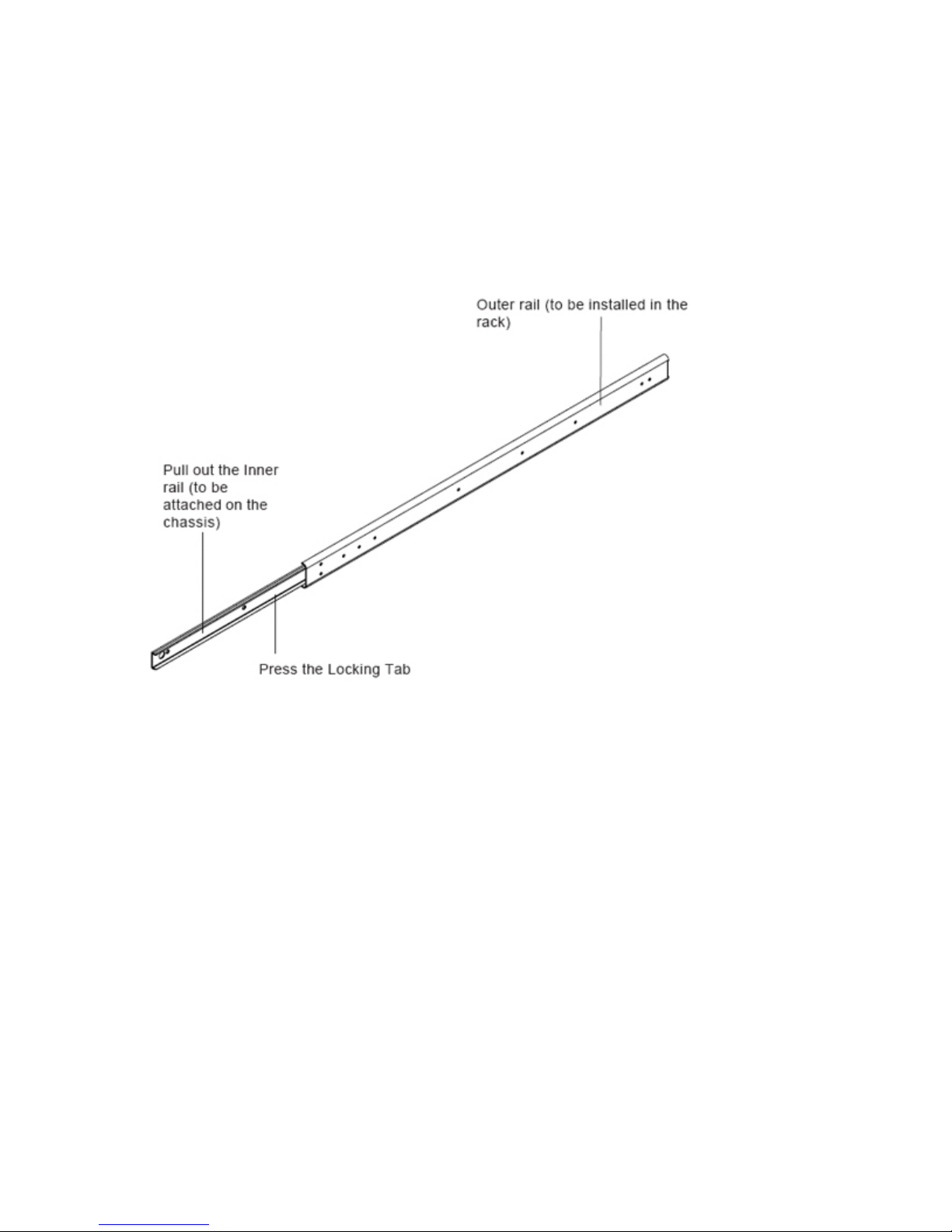
Included in the shipping package are a pair of rail assemblies. In each rail assembly, locate the
inner rail and the outer rail.
1. Press the locking tab to release the inner rail from its locking position and pull out the
inner rail from the rail assembly. (*The inner rails are to be attached to the chassis and
the outer rails are to be installed in the rack.)
Identifying the Sections of the Rack Rails
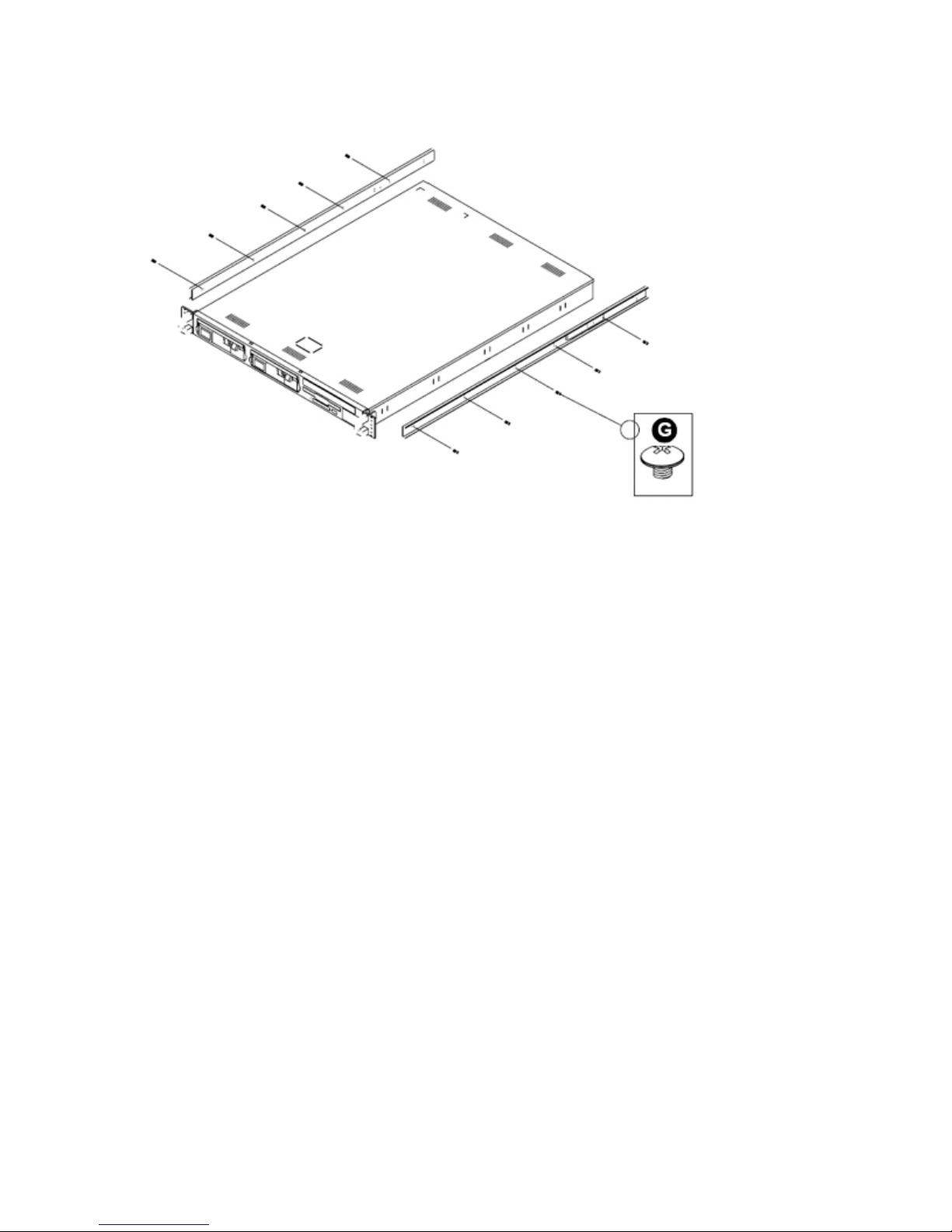
2. Locate the five holes on each side of the chassis and locate the five corresponding holes
on each of the inner rail.
Page 24
MPC Computers, LLC NetFRAME 1420
Locating the Rail Holes
3. Attach an inner rail to each side of the chassis and secure the inner rail to the chassis by
inserting five Type G screws through the holes on the chassis and the inner rail.
4. Repeat the above steps to install other rail on the chassis.
Installing Outer Rails
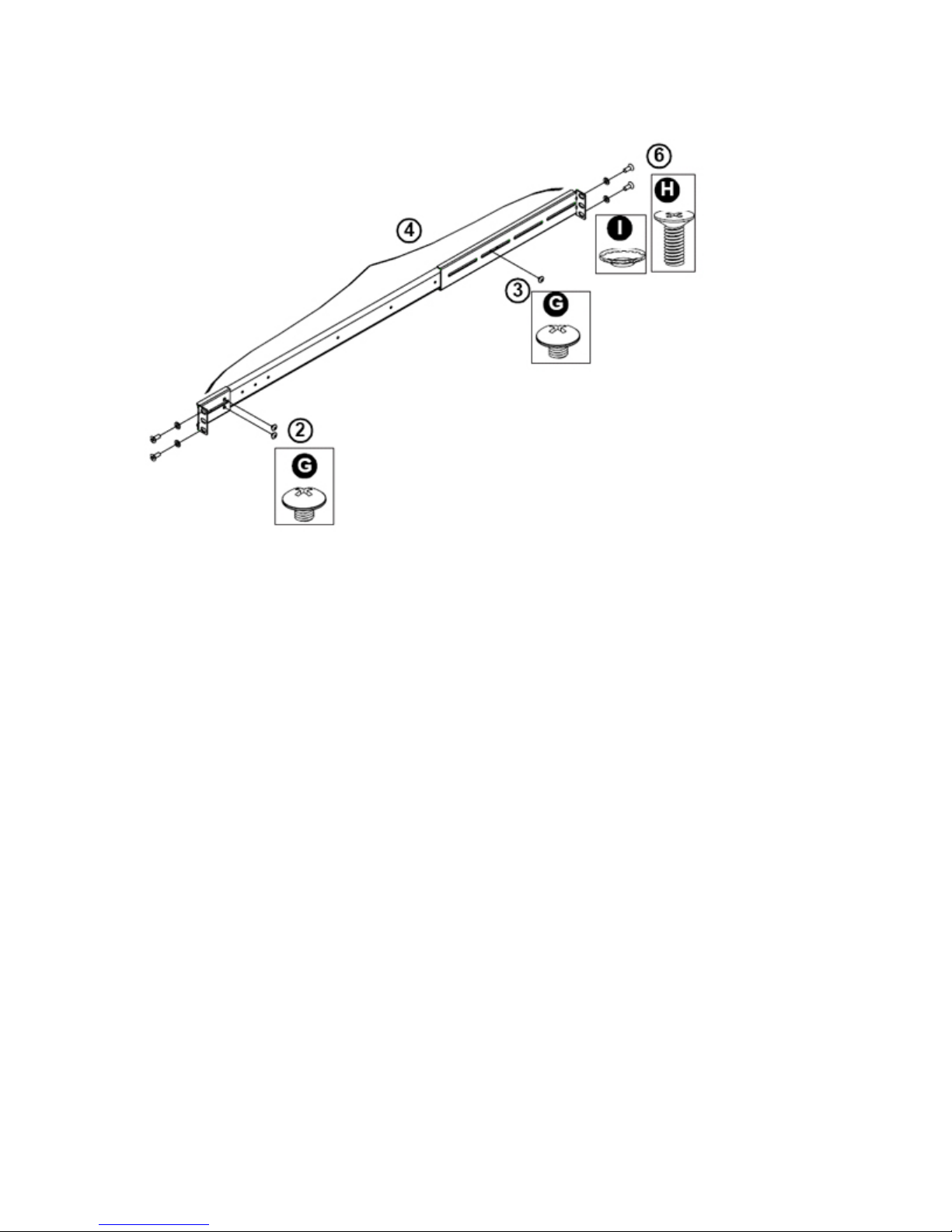
After you have installed the inner rails on the chassis, you are ready to install the outer rails of rail
assemblies to the rack. The rails are designed to fit in the racks with the depth of 28" to 33".
1. In the package, locate a pair of front (-short) and rear (-long) brackets. Please note that
the brackets are marked with Up/Front Arrows (-front) and Up/Rear arrows (-rear).
2. Secure the front (-short) bracket (marked with the Up/Front arrows) to the outer rail with
two Type G screws.
3. Attach the rear (-long) bracket to the other end of the outer rail and secure the rear (long)
bracket to the outer rail with a Type G screw as shown below.
4. Measure the depth of your rack and adjust the length of the rails accordingly.
5. Repeat the same steps install the other outer rail on the chassis.
6. Secure both outer rail assemblies to the rack with Type H screws and Type I washers.
24
Page 25
MPC Computers, LLC NetFRAME 1420
Installing the Chassis Rails
7. Slide the chassis into the rack as shown below. The system may not slide into the rack
smoothly or easily when installed the first time. However, some adjustment to the slide
assemblies might be needed for easy installation.)
8. You will need to release the safety taps on both sides of the chassis in order to
completely remove the chassis out of the rack.
Page 26
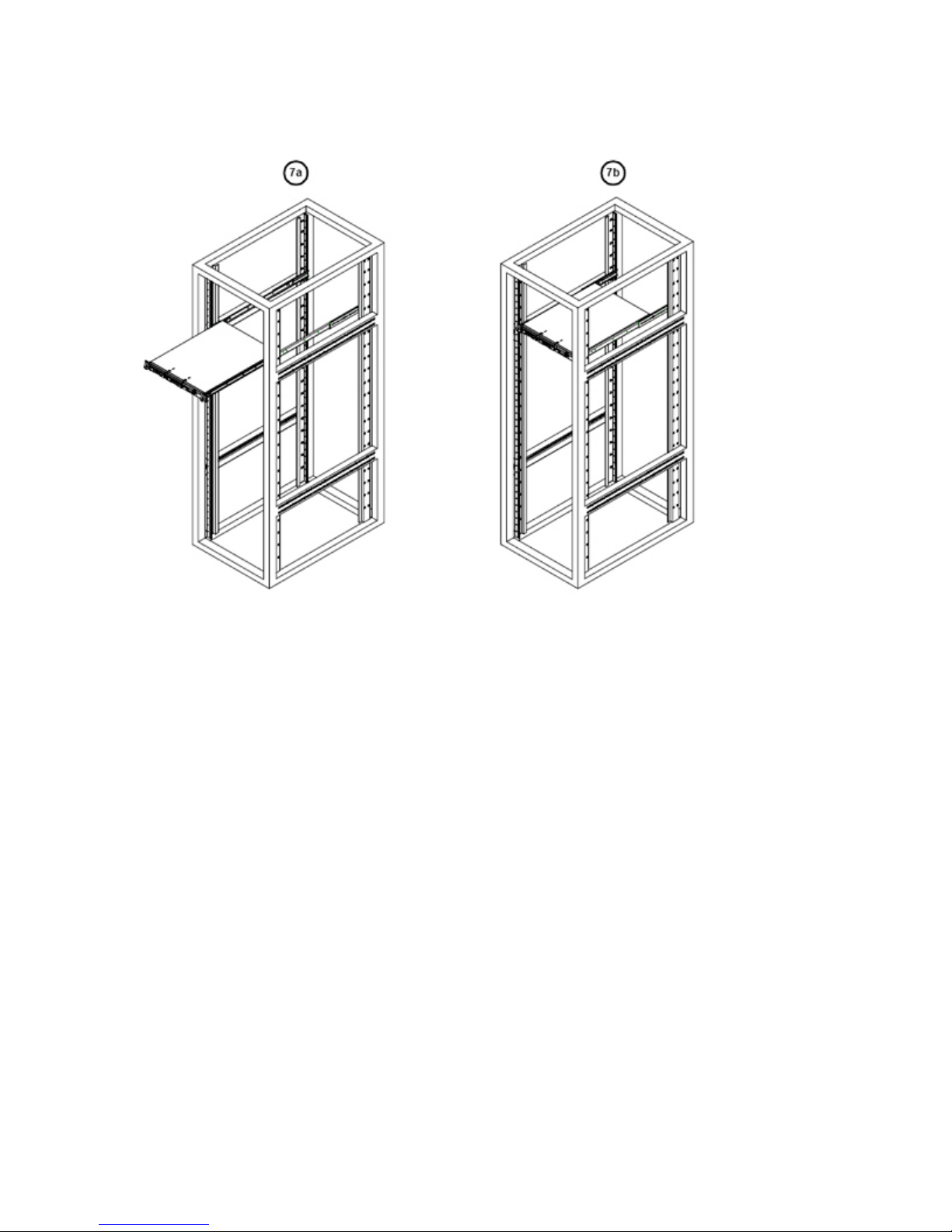
MPC Computers, LLC NetFRAME 1420
Installing the System into the Rack
Open Rack Installation
After you have installed the inner rails on the chassis, you are ready to install the outer rails of rail
assemblies to the rack. The rails are designed to fit in the racks with the depth of 28" to 33".
1. In the package, locate a pair of front (-short) and rear (-long) brackets. Please note that
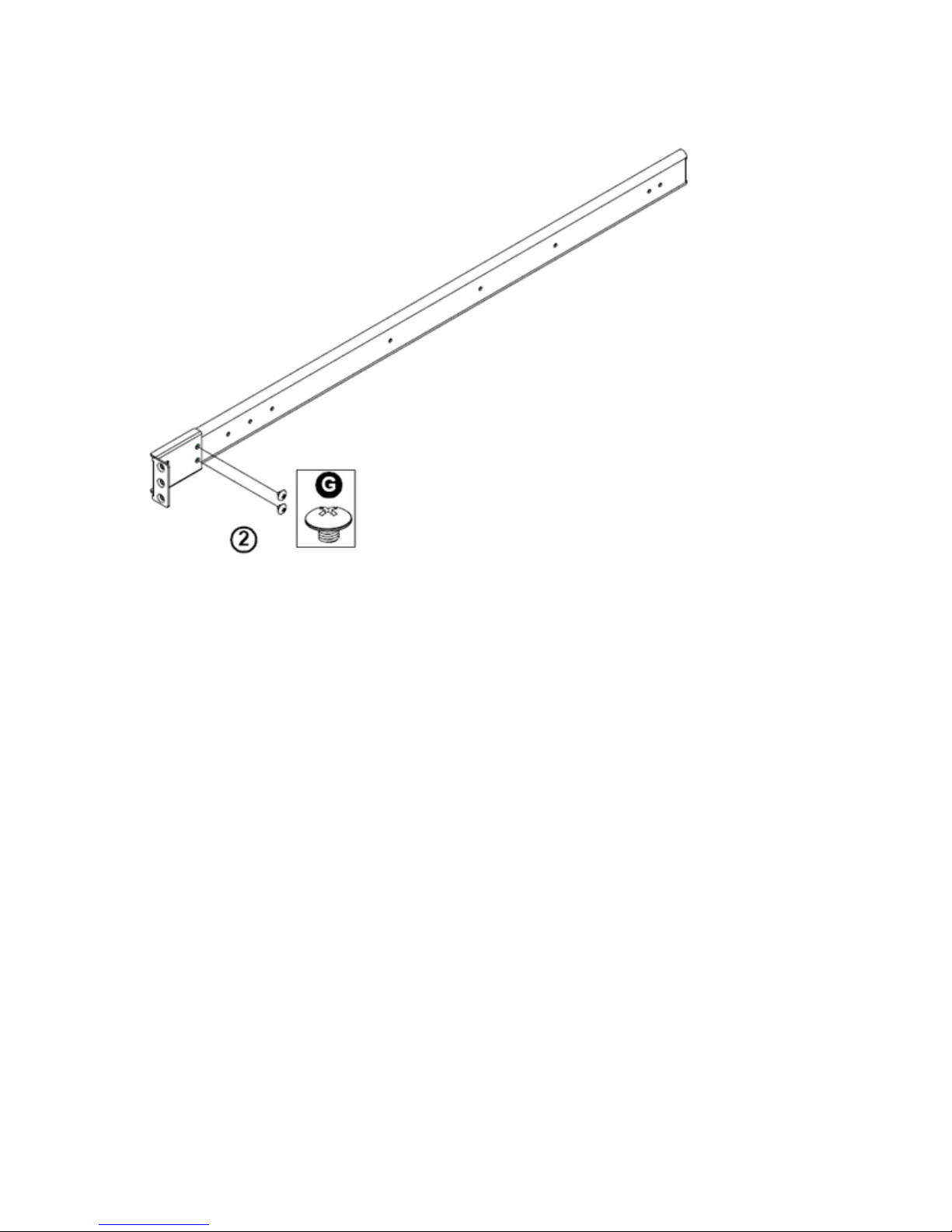
the brackets are marked with Up/Front Arrows (-front) and Up/Rear arrows (-rear).
2. Secure the front (-short) bracket (marked with the Up/Front arrows) to the outer rail with
two Type G screws as shown below:
26
Page 27
MPC Computers, LLC NetFRAME 1420
Securing Type G screws to the Rail
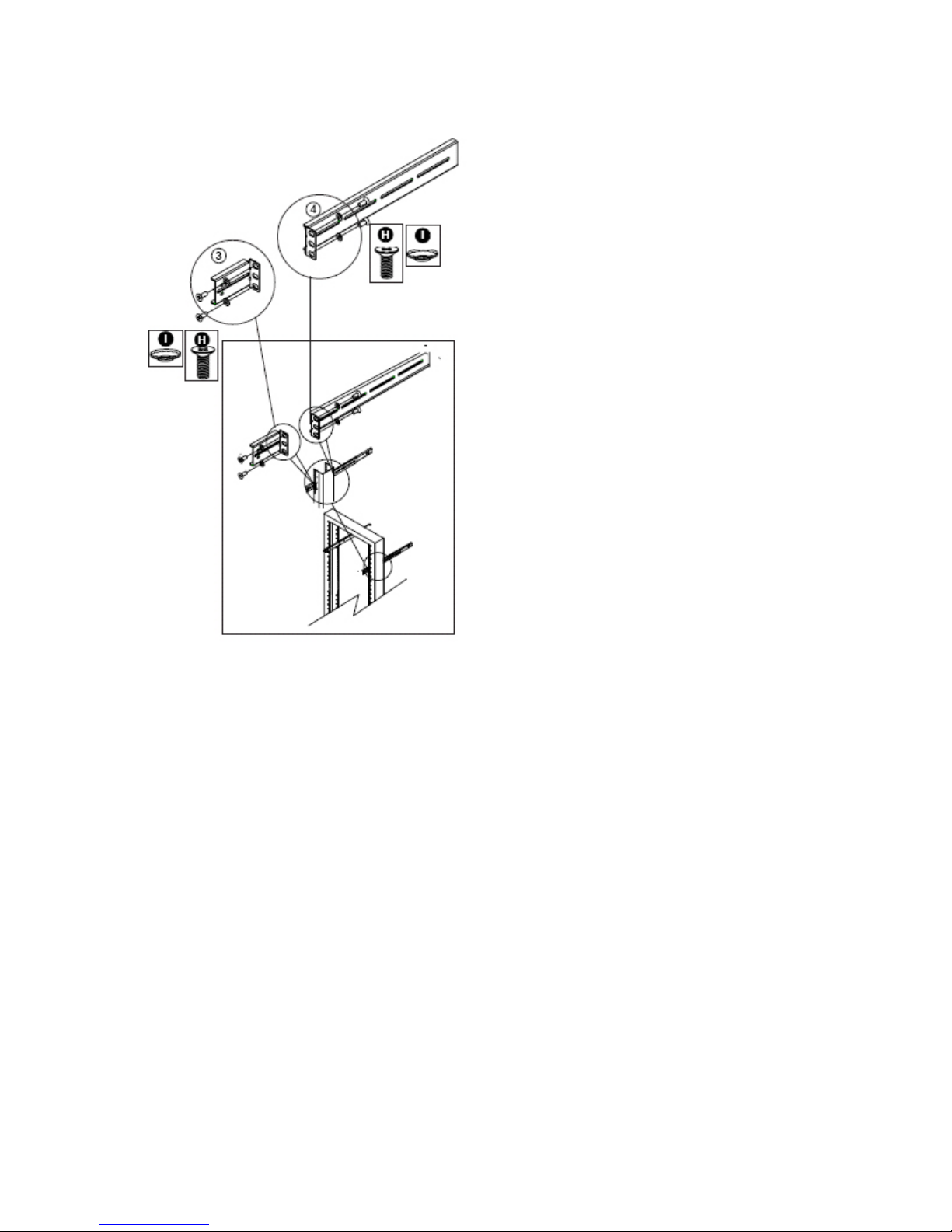
3. Attach the front (-short) bracket to the front end of the rack, and secure it to the rack with
two Type H screws and Type I washers as shown below.
4. Attach the rear (-long) bracket to the rear end of the rack, and secure it to the rack with
two Type H screws and Type I washers as shown below. Repeat the same steps to
install the other outer rail to the other side of rack.
Page 28
MPC Computers, LLC NetFRAME 1420
Installing Rails to Open Rack
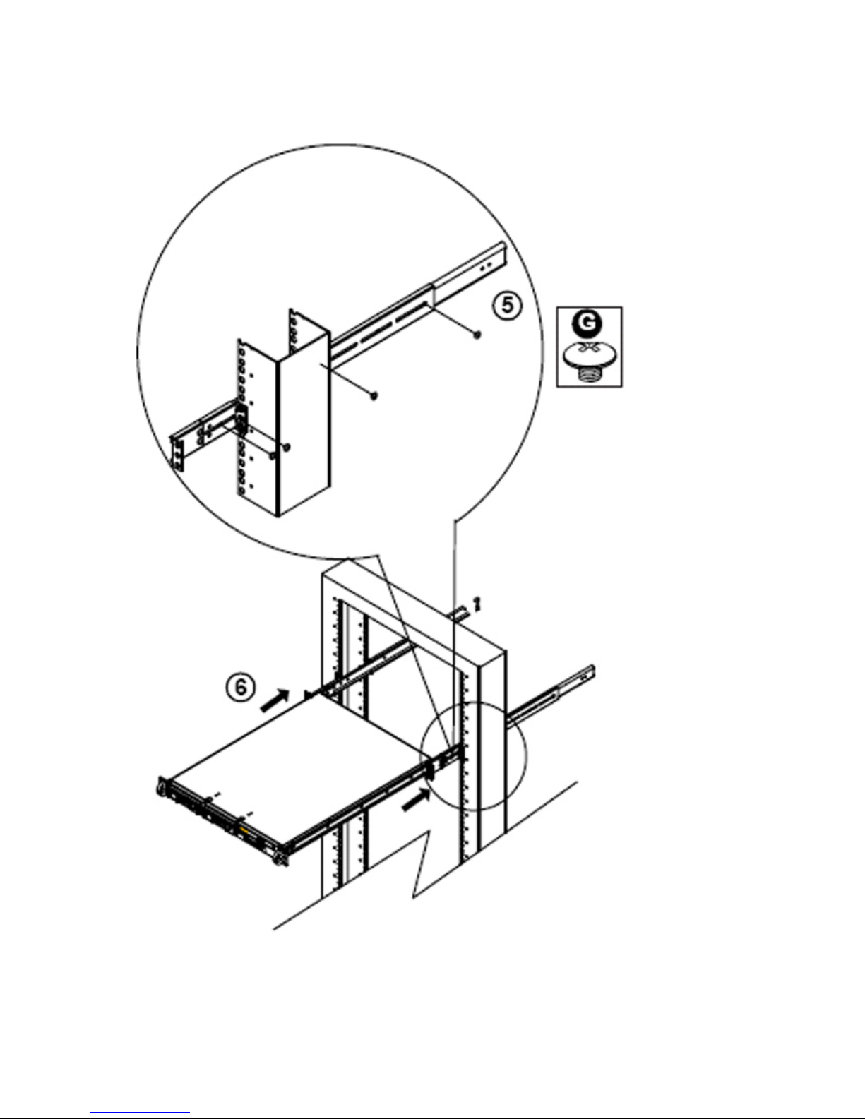
5. Measure the depth of your rack and adjust the length of the rails accordingly. Then,
secure the rails to the chassis with Type G screws.
6. Slide the inner rails which are attached to the chassis into the outer rails on the rack.
28
Page 29
MPC Computers, LLC NetFRAME 1420
Slide System into Rack
Page 30
MPC Computers, LLC NetFRAME 1420
Taking Apart Your System
To remove or replace most drives, memory, or PCI cards, you will need to remove the server's
access panel. The following sections provide information about taking your system apart.
Safety and Preparation
Access Panel
Caution: Modules are Electrostatic Sensitive. A small electrostatic discharge
(ESD) can damage server components. An ESD-damaged module or PCI card
might not fail immediately, but over time it could become worse, possibly
causing an intermittent problem. Be very careful to handle the module or PCI
card ONLY by the edges. DO NOT touch the gold/silver edge-connectors or
any of the components on the system board. Leave the module or PCI card in
the antistatic bag until ready for installation.
Caution: The system board conforms to the new PCI 2.2 specification. This
requires 3.3v standby for all PCI slots, DIMM banks, and PS/2 outputs
(KB/PS/2 Mouse). Always remember to unplug the AC power cord before
adding any PCI cards, memory, or plugging/unplugging the keyboard or
mouse. Otherwise, the system may automatically power up when adding the
component. This could also damage the system board or the component you
are adding and is not covered under warranty.
Safety and Preparation
To avoid personal injury and property damage, please carefully follow all the safety steps listed
below:
Electrostatic Discharge (ESD) Cautions
Leave the module in the antistatic bag until you are ready to install it.
The system should be opened on an ESD-safe workbench, and the technician should
wear an ESD-safe smock with grounding wrist and foot straps.
Keep DIMMs in the antistatic bag while transporting, especially when crossing carpet.
Antistatic wrist straps with clip-on ends are available commercially.
Caution: The system board conforms to the new PCI 2.2 specification. This
requires 3.3v standby for all PCI slots, DIMM banks, and PS/2 outputs
(KB/PS/2 Mouse). Always remember to unplug the AC power cord before
adding any PCI cards, memory, or plugging/unplugging the keyboard or
mouse. Otherwise, the system may automatically power up when adding the
component. This could damage the system board or the component you are
adding and is not covered under warranty.
30
Page 31
MPC Computers, LLC NetFRAME 1420
Safety: Before You Remove the Access Panel
Before removing the access panel for any reason, observe these safety guidelines.
Turn off all peripheral devices connected to the server.
Turn off the server by pressing the power button on the front of the chassis. Then unplug
the AC power cord on the back of the chassis.
Disconnect all peripheral cables and all telecommunication lines connected to the I/O
connectors or ports on the back of the chassis.
Warning: The power button on the front panel DOES NOT turn off the AC
power. To disconnect power from the server, you must unplug the AC power
cord from the wall outlet or the chassis.
Warning: Hazardous electrical conditions may be present on power,
telephone, and communication cables. Turn off the server and disconnect
the power cords, telecommunications systems, networks, and modems
attached to the server before opening the server case. Otherwise, personal
injury or equipment damage can result.
Warning: Hazardous voltage, current, and energy levels are present inside
the power supply. There are no user-serviceable parts inside the po wer
supply; servicing should be performed by technically qualified personnel.
Caution: For proper cooling and airflow, always install the access panel
before turning the server on. Operating the server without the access pan el
in place can damage system parts.
Access Panel
The following sections provide information and instructions for removing the server's access
panel.
Tools needed:
Antistatic strap
Note: If you attempt to remove the access panel on a flat surface, you may need to
use a non-skid surface or a stop behind the chassis.
Removing the Access Panel
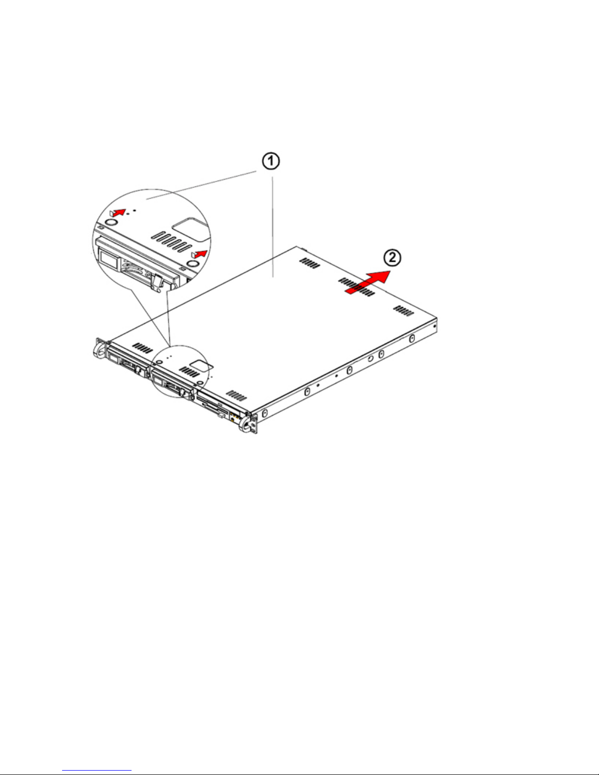
Facing the front of the chassis, the access panel is on the top of the server chassis.
1. Observe the safety precautions.
2. Turn off the server, and unplug the power cord from the power supply, or the server could
accidentally start.
3. Disconnect all the cables and label the cables for easy identification.
4. Use a grounded wrist strap designed to prevent static discharge when handling
components.
Page 32
MPC Computers, LLC NetFRAME 1420
5. Unlock and remove the screws and fasteners to remove the cover or components.
6. Save all the screws and fasteners for later use. (If necessary, label these screws or
fasteners for easy identification.)
7. Press the release tabs to release the cover from its locking position (1).
Removing the Access Panel
8. Once the top cover is released from its locking position, push the cover toward the rear
side and slide it out from the chassis.
32
Page 33
MPC Computers, LLC NetFRAME 1420
Hardware Installation
This section provides detailed instructions on how to remove, install, or replace system devices.
Preparation
Riser/PCI Card
System Fans
Drive Bays
Power Supply
Memory
Processor and Heatsink
Caution: Modules are Electrostatic Sensitive. A small electrostatic discharge
(ESD) can damage server components. An ESD-damaged module or PCI card
might not fail immediately, but over time it could become worse, possibly
causing an intermittent problem. Be very careful to handle the module or PCI
card ONLY by the edges. DO NOT touch the gold/silver edge-connectors or
any of the components on the system board. Leave the new module or PCI
card in the antistatic bag until you are ready to install it. Place the original
module or PCI card in an antistatic bag immediately after removing it from
the system.
Caution: The system board conforms to the PCI 2.2 specification. This
requires 3.3v standby for all PCI slots, DIMM banks, and PS/2 outputs
(KB/PS/2 Mouse). Always remember to unplug the AC power cord before
adding any PCI cards, memory, or plugging/unplugging the keyboard or
mouse. Otherwise, the system may automatically power up when adding the
component. This could also damage the system board or the component you
are adding and is not covered under warranty.
Warning: If the server has been running, any installed processor and heat
sink on the processor board(s) will be hot. To avoid the possibility of a burn,
be careful when removing or installing server board components that are
located near the processors.
Preparation
Complete the following steps before removing or installing hardware.
1. Turn off the server, and unplug the power cord from the power supply, or the server could
accidentally start.
2. Remove all external data cables from the system.
3. Ground yourself.
4. Remove the access panel. (See Access Panel.)
Page 34

MPC Computers, LLC NetFRAME 1420
PCI Riser Card
This system can accommodate either one PCI-X 133 MHz (full length) card or (with the optional
CSE-RR1U-ELi riser card) one PCI-Express x8 card. The PCI slot shields protect the system
board and its components from EMI and aid in proper ventilation, so make sure there is always a
shield covering each unused slot.
To install an add-on card:
1. Push down the PCI riser slot shield retention lever and remove the PCI slot shield.
2. Fully seat the card into the PCI riser card slot, pushing down with your thumbs evenly on
both sides of the card.
3. Finish by securing the PCI riser slot shield retention lever.
System Fans
Three 4-cm fans provide the cooling for the NF1420. Each fan unit is actually made up of two
fans joined back-to-back, which rotate in opposite directions. This counter-rotating action
generates exceptional airflow and works to dampen vibration levels. These fans can adjust their
speed according to the heat level sensed in the system, which results in more efficient and
quieter fan operation. Fan speed is controlled by a setting in BIOS. Each fan in a set has its own
separate tachometer. An air shroud is also included with the system to optimize airflow. Note: It is
very important that the chassis top cover is properly installed for the airflow to circulate properly
through the chassis and cool the components.
System Fan Failure
If a fan fails, the remaining fans will ramp up to full speed and the overheat/fan fail LED on the
control panel will blink on and off. Replace any failed fan at your earliest convenience with the
same type and model (the system can continue to run with a failed fan). Remove the top chassis
cover while the system is still running to determine which fan unit has failed, then power down the
system to replace it. Removing the power cord(s) is also recommended as a safety precaution.
Replacing System Cooling Fan
Removing a Fan
The following information describes how to remove the blower fan.
1. Turn off the power to the system.
2. Remove the chassis cover and unplug the fan cable from the system board.
3. Grasp the failed fan unit and lift it out of the chassis.
Installing a New Fan
Replace the failed fan with an identical 4-cm, 12 volt fan.
1. At the bottom of each fan unit there are four small rubber pieces that help position the fan
into place in the chassis. Remove these from the failed fan and attach them to the new
fan (new fans do not include this piece).
2. Then place the new fan in the housing with the fan wiring toward the system board.
3. Reconnect the fan wiring to the same fan header you removed it from.
34
Page 35
MPC Computers, LLC NetFRAME 1420
4. Power up the system and check that the fan is working properly and that the LED on the
control panel has turned off. Finish by replacing the chassis cover.
Drive Bays
Warning: Power down the system before installing or removing CD-ROM,
floppy, or IDE drives.
Accessing the Drive Bays
Serial ATA Drives: Because of their hot-swap capability, you do not need to access the inside of
the chassis or power down the system to install or replace Serial ATA drives. Proceed to the next
step for instructions.
CD-ROM/Floppy Disk Drives: For installing/removing a CD-ROM or floppy disk drive, you will
need to gain access to the inside of the system by removing the top cover of the chassis.
Note: Only a "slim" CD-ROM drive will fit into this system.
Serial ATA Drive Installation
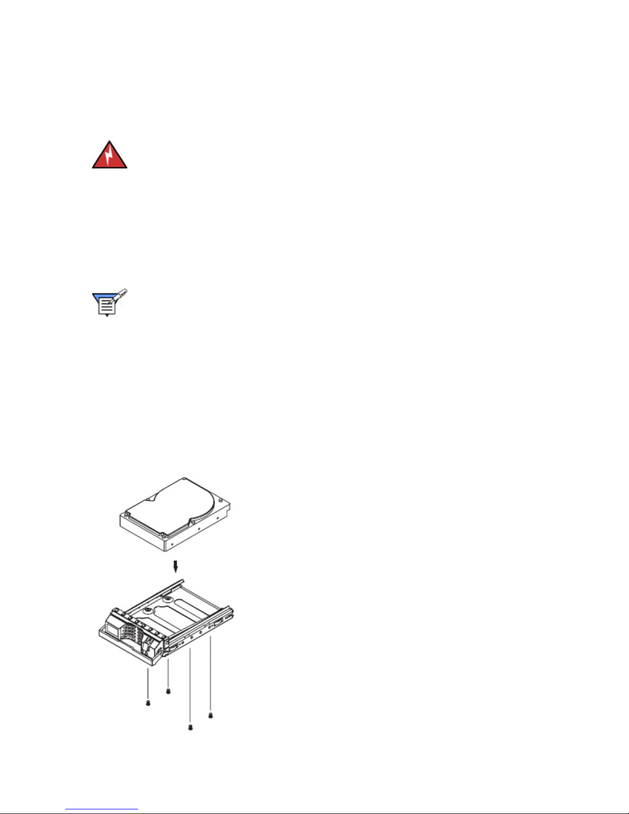
1. Mounting a Serial ATA drive in a drive carrier
The Serial ATA drives are mounted in drive carriers to simplify their installation and removal from
the chassis. These carriers also help promote proper airflow for the Serial ATA drive bays. For
this reason, even empty carriers without Serial ATA drives installed must remain in the chassis.
To add a new Serial ATA drive, install a drive into the carrier with the printed circuit board side
toward the carrier so that the mounting holes align with those in the carrier. Secure the drive to
the carrier with four screws, as shown in the figure below.
Mounting a Drive in a Carrier
Page 36
MPC Computers, LLC NetFRAME 1420
2. Installing/removing hot-swap Serial ATA drives
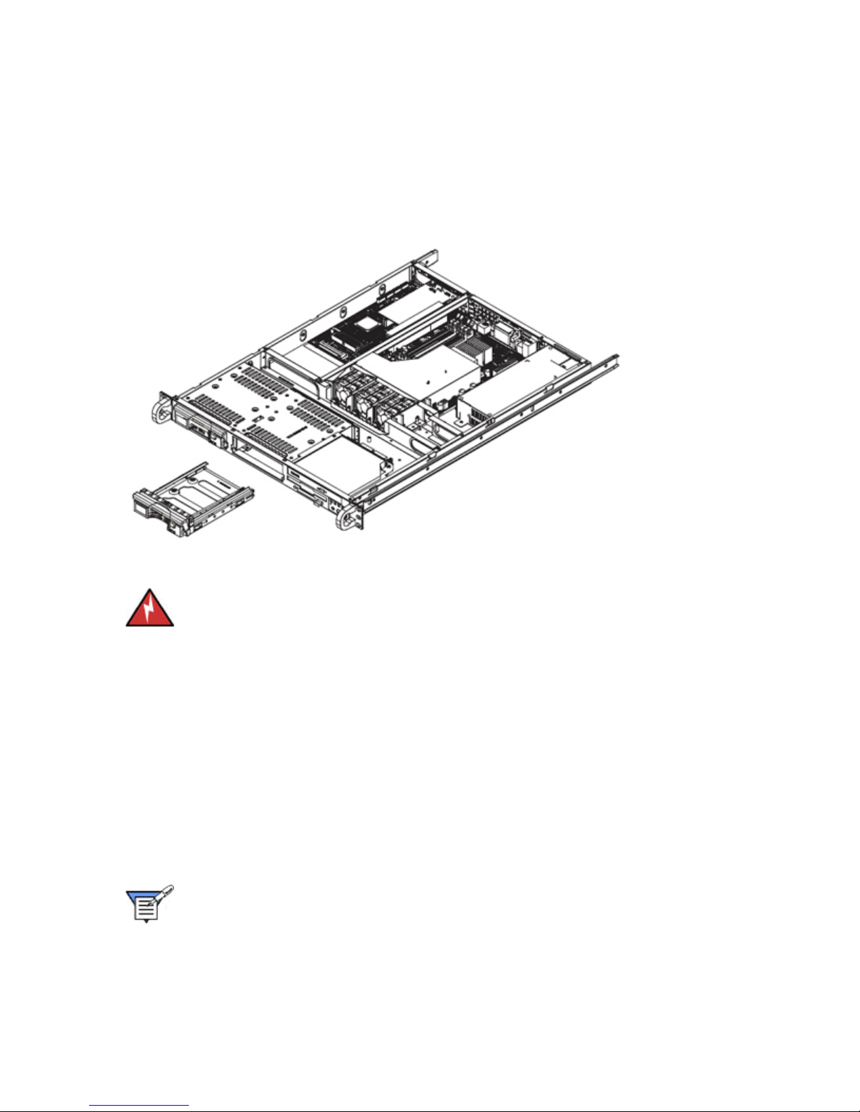
Two Serial ATA drive bays are located in the front of the chassis, making them easily accessible
for installation and removal. These drives are hot-swappable, meaning they can be installed and
removed without powering down the system. To remove, first push the release button located
beside the drive LEDs, then swing the colored handle fully out and use it to pull the unit straight
out.
Removing/Installing Serial ATA Drives
Warning: Regardless of how many Serial ATA drives are installed, both drive
carriers must remain in the drive bays to maintain proper airflow.
Serial ATA Power Cables
Serial ATA power cables should be routed so that they do not block the airflow through the
chassis.
Serial ATA Backplane
The Serial ATA drives plug into a backplane that provides power, drive ID, and bus termination. A
RAID controller can be used with the backplane to provide data security. The operating system
you use must have RAID support to enable the hot-swap capability of the Serial ATA drives.
Replacing a CD-ROM or Floppy Drive
Note: Only a "slim" CD-ROM drive and a "slim" floppy drive will fit in the chassis.
The top cover of the chassis must be opened to gain full access to the CD-ROM and floppy drive
bays.
1. Remove the retention screws that secure the CD/floppy mounting bracket.
36
Page 37

MPC Computers, LLC NetFRAME 1420
2. Remove the cables from the back of the unit.
3. Remove the CD/floppy assembly from the mounting bracket. To remove either the CD or
floppy drive, remove the screws that secure the assembly to the mounting bracket.
4. Attach the cables to the replacement CD/floppy assembly, align the assembly in the
system, and replace the retention screws.
A red mark on a wire typically designates the location of pin 1.
Power Supply
As with all computer products, a stable power source is necessary for proper and reliable
operation. It is even more important for processors that have high CPU clock rates of 1 GHz and
faster.
This server accommodates has a single 300 watt power supply. This power supply has the
capability of operating at 100 - 240 input volts. Depress the main power button on the front of the
chassis and then unplug the AC power cord to completely remove power from the system before
removing the power supply.
Warning: Depress the main power button on the front of the chassis, and
then unplug the AC power cord to completely remove power from the system
before removing the power supply.
Power Supply Failure
If the power supply unit fails, the system will shut down and you will need to replace the power
supply unit.
Replacing the Power Supply
Removing the Power Supply
The information below describes how to remove the power supply.
1. Unplug the power cord from the system.
2. Remove the top chassis cover.
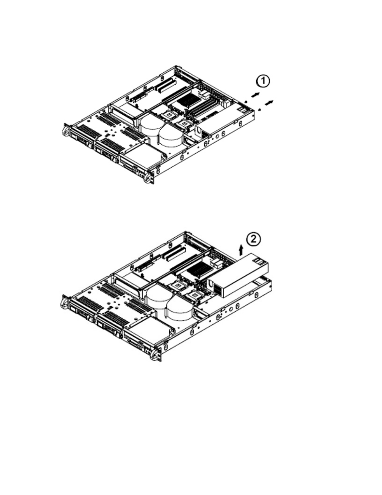
3. Remove the two screws from the power supply panel (1).
Page 38
MPC Computers, LLC NetFRAME 1420
Removing Screws
4. Lift the power supply out of the chassis (2).
Removing the Power Supply
38
Page 39

MPC Computers, LLC NetFRAME 1420
Installing a New Power Supply
Caution: Replace the failed unit with another unit of the same wattage. MPC
highly recommends that you replace it with the exact same type of power
supply.
The information below describes how to install a new power supply.
1. Carefully insert the new unit into position in the chassis and secure it with the two screws
removed earlier.
2. Replace the chassis top cover.
3. Reconnect the power cord.
4. Push the unit back into the rack.
5. Turn on the power switch on the power supply.
6. Depress the power button on the front of the system.
Memory
Caution: To prevent damage, exercise extreme care when installing
or removing DIMM modules.
Memory Support
The NF1420 supports Dual channel, ECC unbuffered DDR II 667/533/400 SDRAM. Both
interleaved and non-interleaved memory are supported, so you may populate any number of
DIMM slots. (Populating DIMM#1A,DIMM#1B, and/or DIMM#2A, DIMM#2B with memory modules
of the same size and of the same type will result in dual channel, two-way interleaved memory
which is faster than the single channel, non-interleaved memory. When ECC memory is used, it
may take 25-40 seconds for the VGA to display.)
Notes:
1. Due to chipset limitation, 8GB Memory can only be supported by the following operating
systems:
32-Bit: Windows 2000 Advanced Server, Windows Server 2003 Enterprise Edition;
64-Bit: Windows Server 2003 Standard x64 Edition, Windows XP Professional x64 Edition,
Windows Server 2003 Enterprise x64 Edition.
2. You may install a maximum of 2GB DIMMs on each slot; however, only DDR II 533 MHz
2GB density modules are available for this configuration.
3. Some old-version of DDR II-667 may not match Intel's On-Die-Temperature requirement
and will automatically be down-graded to run @ 533 MHz, If this occurs, contact your
memory vendor to check the ODT value.
Page 40
MPC Computers, LLC NetFRAME 1420
Installing Memory Modules
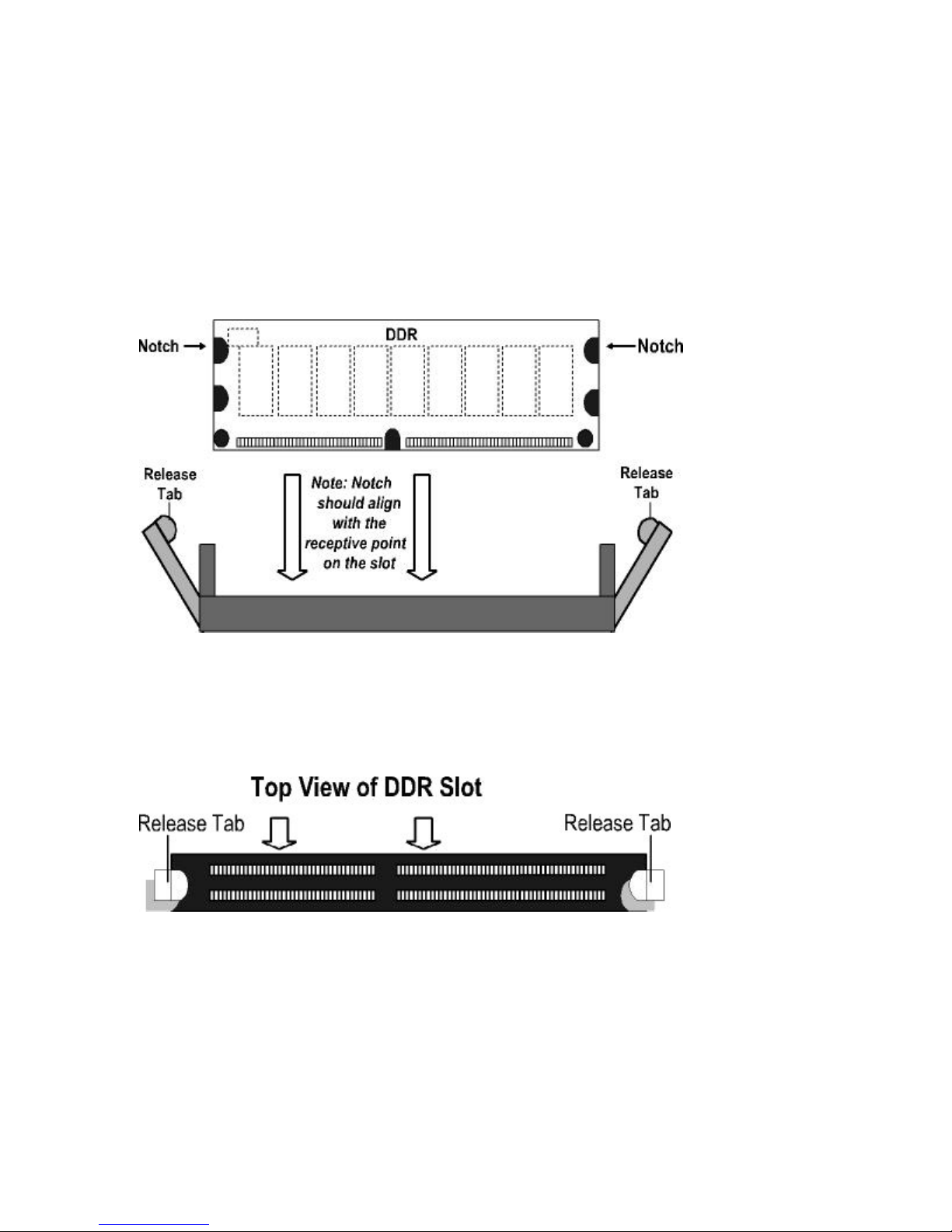
The information below describes how to install a memory module.
1. Insert each memory module vertically into a DIMM slot.
2. Pay attention to the notch along the bottom of the module to prevent inserting it
incorrectly.
3. Gently press down on the DIMM module until it snaps into place in the slot.
Side View of DDR Module Installation into Slot
Removing Memory Modules
The information below describes how to remove a memory module.
Use your thumbs to gently push each release tab outward to free the DIMM from the slot.
Top View of DDR Slot
40
Page 41
MPC Computers, LLC NetFRAME 1420
Processor and Heatsink
This section describes how to install a processor and heatsink.
Caution: When handling the processor package, avoid placing direct
pressure on the label area of the fan.
Caution: Always connect the power cord last, and always remove it before
adding, removing, or changing any hardware components. Make sure that
you install the processor into the CPU socket before you install the CPU
heatsink.
Caution: Avoid placing direct pressure to the top of the processor package.
Always remove the power cord first before adding, removing, or changing
any hardware components.
Installing the Processor
The information below describes how to install a processor.
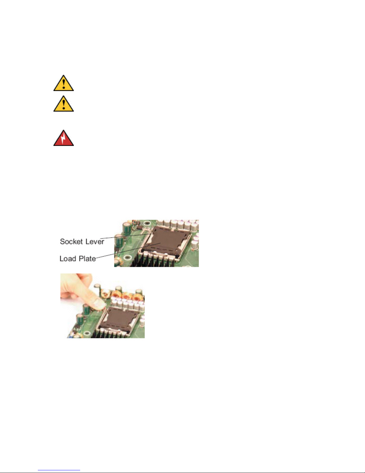
1. Press the socket lever to release the load plate, which covers the CPU socket, from its
locking position.
Socket Lever and Load Plate
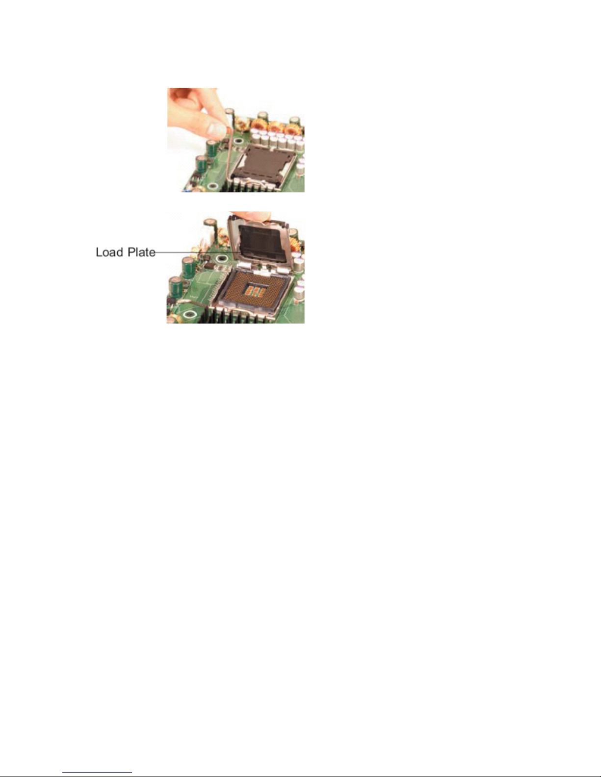
2. Gently lift the socket lever to open the load plate.
Page 42
MPC Computers, LLC NetFRAME 1420
Lifting Socket Lever
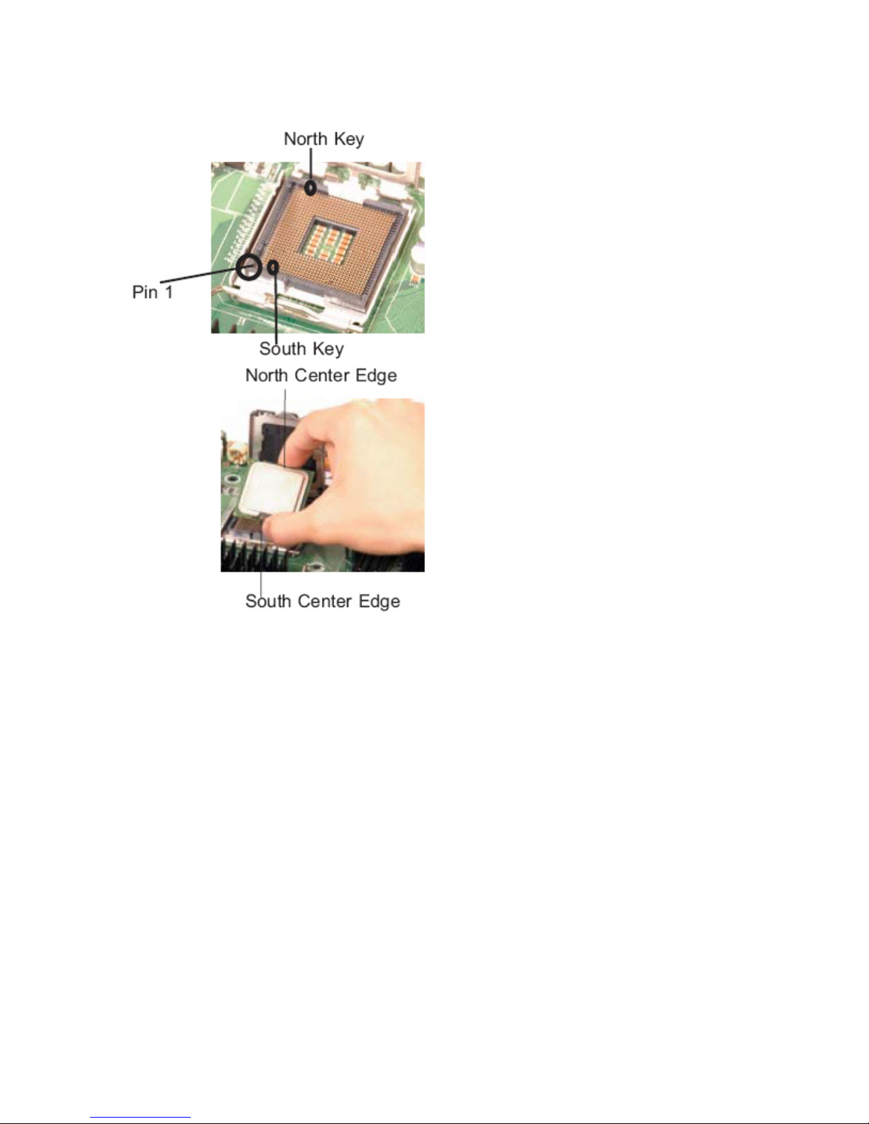
3. Locate Pin 1 on the CPU socket. (*Note: Pin 1 is the corner marked with a triangle).
Please note that the North Key and the South Key are located vertically in the CPU
housing.
4. Use your thumb and your index finger to hold the CPU at the North Center Edge and the
South Center Edge of the CPU.
5. Align Pin 1 of the CPU with Pin 1 of the socket. Once aligned, carefully lower the CPU
straight down and into the socket. Do not drop the CPU on the socket. Do not move the
CPU horizontally or vertically. Do not rub the CPU against the surface of the socket or
against any pins of the socket, which may damage the CPU and/or the socket.
42
Page 43
MPC Computers, LLC NetFRAME 1420
Placing the CPU
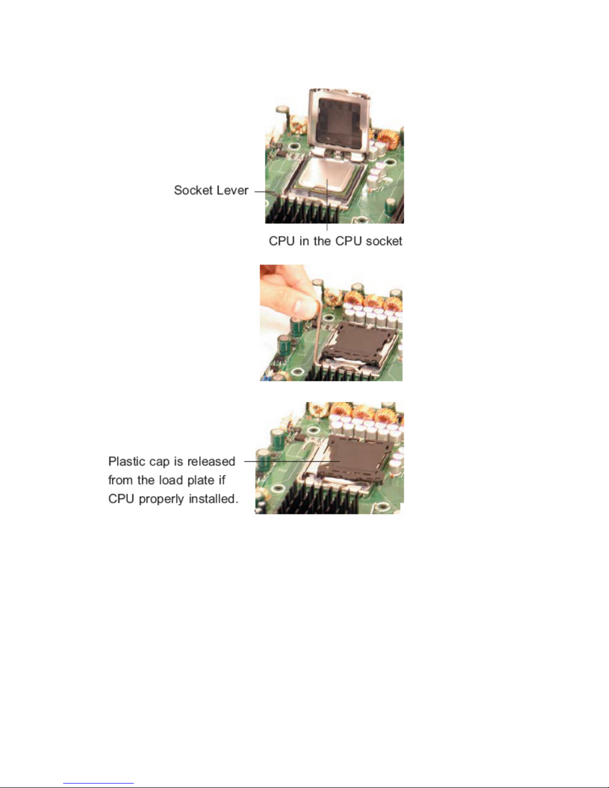
6. With the CPU inside the socket, inspect the four corners of the CPU to make sure that
the CPU is properly installed.
7. Use your thumb to gently push the lever down and lock it in the hook.
8. If the CPU is properly installed into the socket, the plastic cap will be automatically
released from the load plate when the lever is pushed into the hook. Remove the plastic
cap from the system board.
Page 44
MPC Computers, LLC NetFRAME 1420
Installing the CPU
Installing the Heatsink
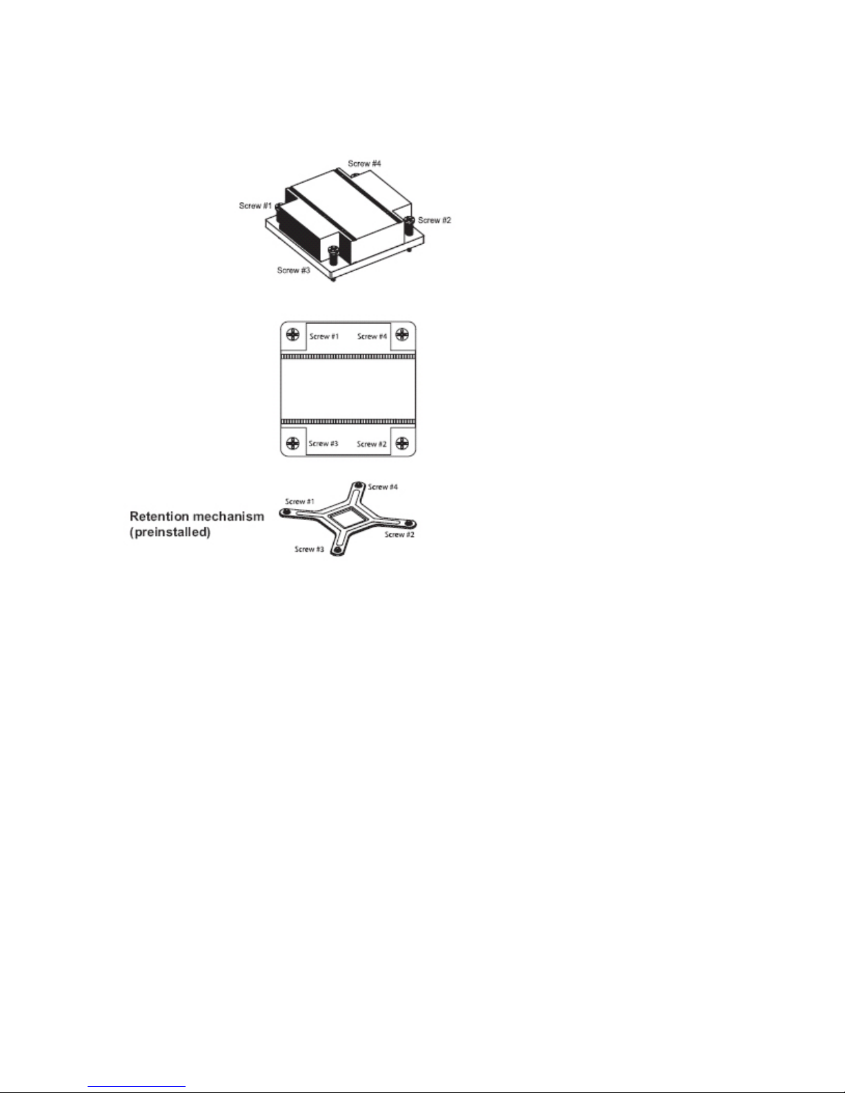
1. Do not apply any thermal grease to the heatsink or the CPU die; the required amount has
already been applied.
2. Place the heatsink on top of the CPU so that the four mounting holes are aligned with
those on the retention mechanism.
3. Screw in two diagonal screws (eg. the #1 and the #2 screws) until just snug (do not fully
tighten the screws, which may damage the CPU).
4. Finish the installation by fully tightening all four screws.
44
Page 45
MPC Computers, LLC NetFRAME 1420
Installing the Heatsink
Removing the Heatsink
1. Unplug the power cord from the power supply.
2. Unscrew and remove the heatsink screws.
3. Hold and gently wriggle the heatsink to loosen it from the CPU. (Do not use excessive
force when loosening the heatsink!)
4. Once the heatsink is loosened, remove it from the CPU socket.
5. Clean the surfaces of the CPU and the heatsink to remove the old thermal grease.
Reapply the proper amount of thermal grease on the surface before re-installing the
heatsink.
Page 46
MPC Computers, LLC NetFRAME 1420
System Board
The following sections contain information about system features, PC health monitoring, jumpers,
power configuration settings, the I/O chip, and the installation of your system board.
Features and Specifications
PC Health Monitoring
Jumper Settings
Power Configuration Settings
System Board Installation
Software Installation
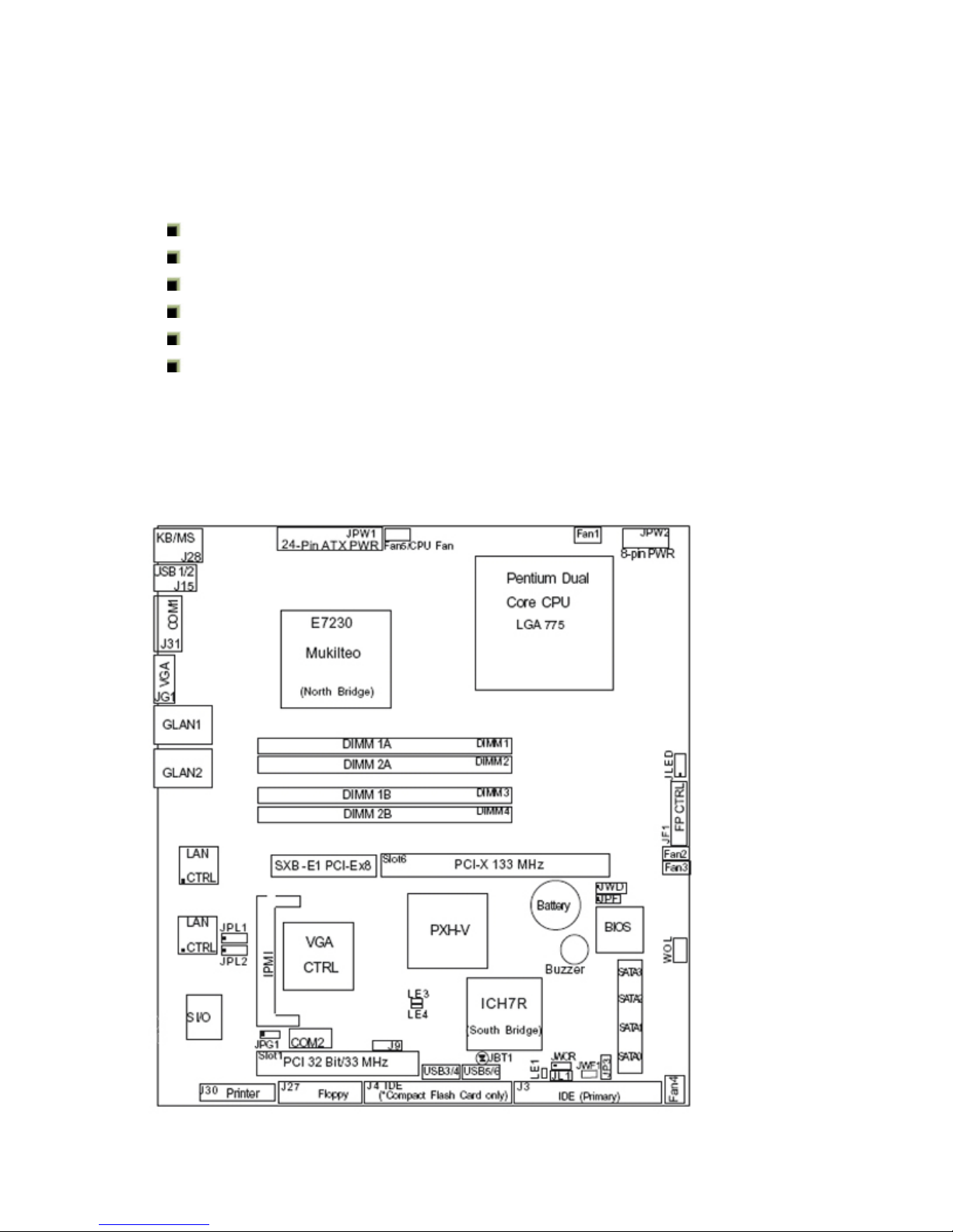
System Board Features and Specifications
The following is a general outline of the system board features and specifications.
System Board Layout (not drawn to scale)
46
Page 47

MPC Computers, LLC NetFRAME 1420
System Board Specifications
Feature Specifications
CPU
Memory
Chipset
Expansion
Slots
BIOS
System Board
Single Intel® Celeron® D, or Intel® Pentium® 4, or Intel®
Pentium® D Processor (LGA 775 Socket)
Four DIMM sockets supporting up to 8GB ECC DDR2 SDRAM
Intel E7230 chipset
One universal PCI-X 133 MHz/PCI-Express x8 slot and one 32-bit,
33 MHz (5V) PCI slot. The PCI-X 133 MHz slot is available for use
with the riser card included with the system (the PCI-Express x8
slot is available for use with the optional CSE-RR1U-ELi riser
card).
8 Mb Phoenix® Flash ROM
Form Factor: ATX
Dimensions: 12 x 9.6 in (305 x 244 mm)
PC Health
Monitoring
ACPI Features
Onboard I/O
Onboard voltage monitors for CPU cores, Chipset Voltage,
Memory Voltage, +3.3V, +5V, +5V Standby, +12V, and −12V
CPU 4-phase-switching voltage regulator
Status monitor for fan speed & System OH/Fan Fail LED/Control
Pulse Width Modulation Fan Control & Low noise fan speed control
Environmental temperature monitoring via BIOS, PWR-Up from AC
PWR loss
Slow blinking LED for suspend state indicator
BIOS support for USB keyboard
Main switch override mechanism
Internal/external modem ring-on
1 ATA/100 EIDE Channel
Intel ICH7R SATA Controller, 4 connectors for 4 devices with
support of RAID functions 0, 1, 5 and 10
1 floppy port interface (up to 2.88 MB)
1 Fast UART 16550 compatible serial port and 1 header
Two Intel single-port 82573 PCI-E Gigabit Ethernet Controller
Page 48

MPC Computers, LLC NetFRAME 1420
PS/2 mouse and PS/2 keyboard ports
Up to 6 USB (Universal Serial Bus) 2.0 ports for a speed
VGA Connector
Low Profile IPMI 2.0
Super I/O (Winbond 83627 HF) with hardware monitoring
(W83792DL)
ATI Rage XL 8 MB
Temperature
Other
Monitoring CPU, chassis environment
CPU Thermal Trip support
Thermal Monitor 2 (TM2) (available if supported by the CPU)
Wake-on-LAN (WOL)
Wake-on-Ring (WOR)
Onboard Standby PWR warning LED Indicator ("LE 1")
CD Utilities
Dimensions
Drivers and software for Intel E7230 chipset utilities
9.6" (W) x 12" (L) (243.84 mmx 304.8 mm)
PC Health Monitoring
This section describes the PC health monitoring features of the NF1420. The system board has
an onboard System Hardware Monitor chip that supports PC health monitoring.
Fan Status Monitor with Firmware Speed Control
The PC health monitor can check the RPM status of the cooling fans. The onboard fans are
controlled by Thermal Management via BIOS.
CPU Overheat/Fan Fail LED and Control
This feature is available when the user enables the CPU overheat warning function in the BIOS.
This allows the user to define an overheat temperature. When this temperature reaches the
threshold, the CPU thermal trip feature will be activated and it will send a signal to the Speaker
LED and, at the same time, the CPU speed will be decreased. It will also activate the alarm if a
fan failure occurs.
48
Page 49
MPC Computers, LLC NetFRAME 1420
Jumper Settings
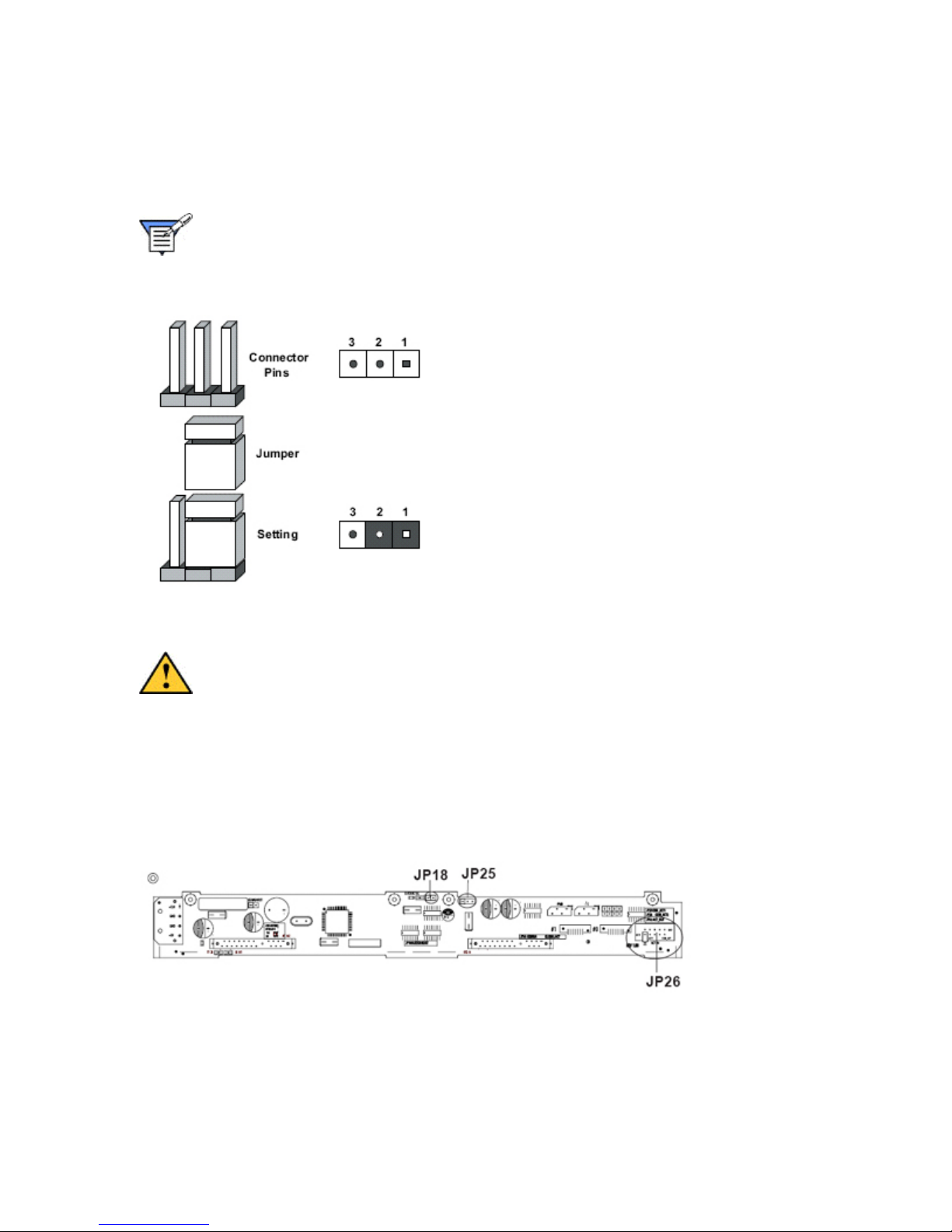
To modify the operation of the motherboard, jumpers can be used to choose between optional
settings. Jumpers create shorts between two pins to change the function of the connector. Pin 1
is identified with a square solder pad on the printed circuit board.
Note: On a two-pin jumper, Closed means the jumper is on both pins and Open
means the jumper is either on only one pin or completely removed.
Jumper Settings
The figure below shows the locations of the system board's jumpers, and the table explains the
settings for the configuration jumpers.
Caution: Some jumpers have a small tab on top that you can grip with your
fingertips, forceps, or with a pair of fine needle-nosed pliers. If your jumpers
do not have such a tab, take care when using needle-nosed pliers to remove
or install a jumper; grip the narrow sides of the jumper with the pliers; never
grip the wide sides. Gripping the wide sides can damage the contacts inside
the jumper, causing intermittent problems with the function controlled by
that jumper. Take care to grip with, but not squeeze, the pliers or other tool
you use to remove a jumper, or you may bend or break the stake pins on the
board.
SATA Backplane Jumpers
Page 50

MPC Computers, LLC NetFRAME 1420
SATA Backplane Jumper Configurations
Jumper Name Default Setting Description
JP18 Open Buzzer Reset
JP25 1-2 Overheat Temperature 50°C
JP26 Open Common Activity In and
Act#1~Act#2 In
System Board Jumpers
CMOS Clear
JBT1 is used to clear CMOS. Instead of pins, this "jumper" consists of contact pads to prevent the
accidental clearing of CMOS.
To clear CMOS,
1. First power down the system and unplug the power cord(s)
2. With the power disconnected, short the CMOS pads with a metal object such as a small
screwdriver
3. Remove the screwdriver (or shorting device).
4. Reconnect the power cord(s) and power on the system.
Note: Do not use the PW_ON connector to clear CMOS.
50
Page 51
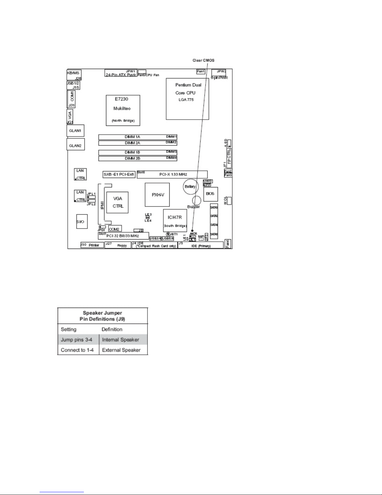
MPC Computers, LLC NetFRAME 1420
System Board Jumper JBT1
Speaker Jumper/Connector
To use the internal (onboard) speaker, place a jumper on pins 3-4 of J9. If you wish to use an
external speaker, connect the speaker header to all four pins of J9.
Speaker Jumper Pin Definitions
JLAN1 Enable/Disable
Change the setting of jumper JPL1 to enable or disable the JLAN1 Ethernet port on the
motherboard. The default setting is enabled.
Page 52
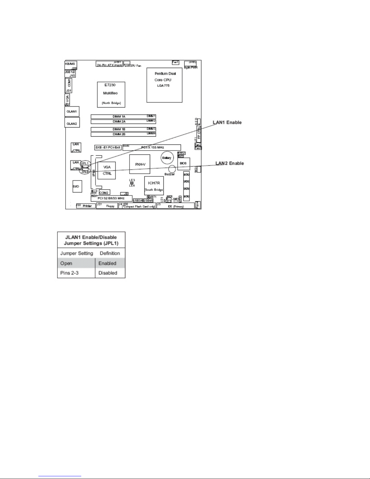
MPC Computers, LLC NetFRAME 1420
System Board Jumpers JPL1 and JPL2
JLAN1 Jumper Settings
JLAN2 Enable/Disable
Change the setting of jumper JPL2 to enable or disable the JLAN2 Ethernet port on the
motherboard. The default setting is enabled.
52
Page 53
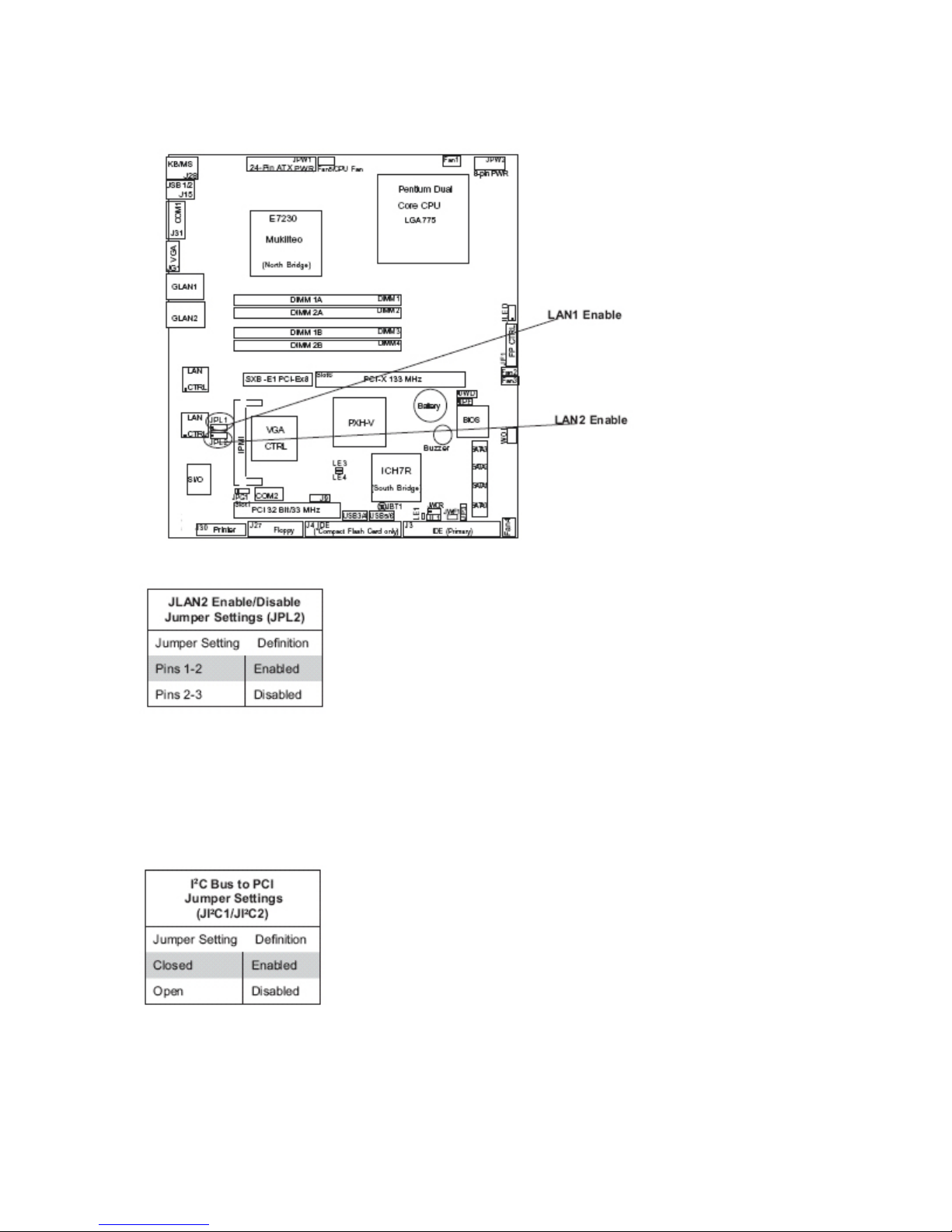
MPC Computers, LLC NetFRAME 1420
System Board Jumpers JPL1 and JPL2
JLAN2 Jumper Settings
2
I
C Bus to PCI
Jumpers JI
2
(I
C) Bus. The default setting is “Open” to disable the connection. Both jumpers must be set to
2
C1 and JI2C2 allow you to connect the PCI/PCI-X slots to the System Management
the same setting.
2
C Bus to PCI Jumper Settings
I
Page 54
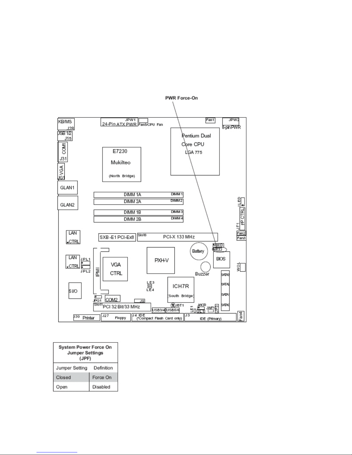
MPC Computers, LLC NetFRAME 1420
Power Force On Enable
Jumper JPF allows you to enable or disable the Force-Power-On function. If enabled, system
power will always stay on. If disabled (the normal setting), the user needs to press the power
button to power on the system.
Power Force On Jumper
Power Force On Jumper Settings
54
Page 55
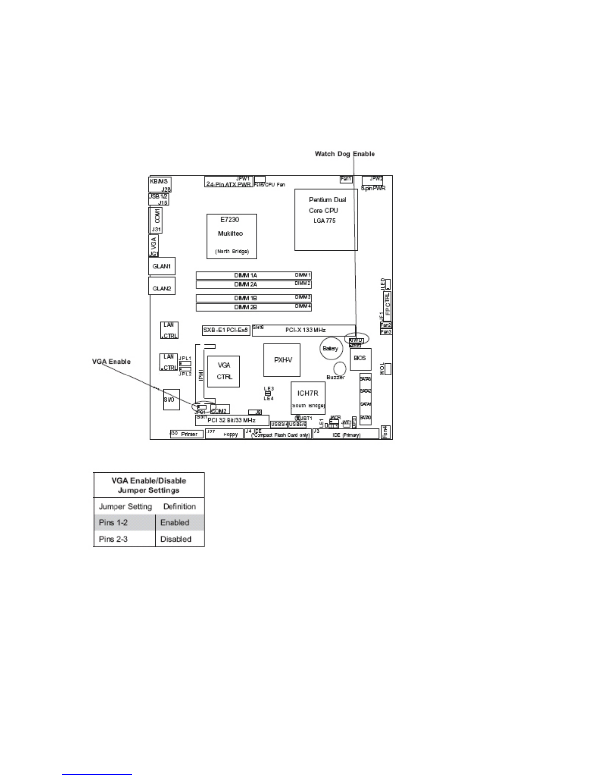
MPC Computers, LLC NetFRAME 1420
VGA Enable/Disable
JPG1 allows you to enable or disable the VGA port. The default position is on pins 1 and 2 to
enable VGA.
Watch Dog and VGA Jumpers
VGA Jumper Settings
Watch Dog Enable
JWD controls the Watch Dog function. Watch Dog is a system monitor that can reboot the system
when a software application is “hung up”. Pins 1-2 will cause WD to reset the system if an
application is hung up. Pins 2-3 will generate a non-maskable interrupt signal for the application
that is hung up. Watch Dog must also be enabled in BIOS. When enabled, the user needs to
write their own application software in order to disable the Watch Dog Timer.
Page 56
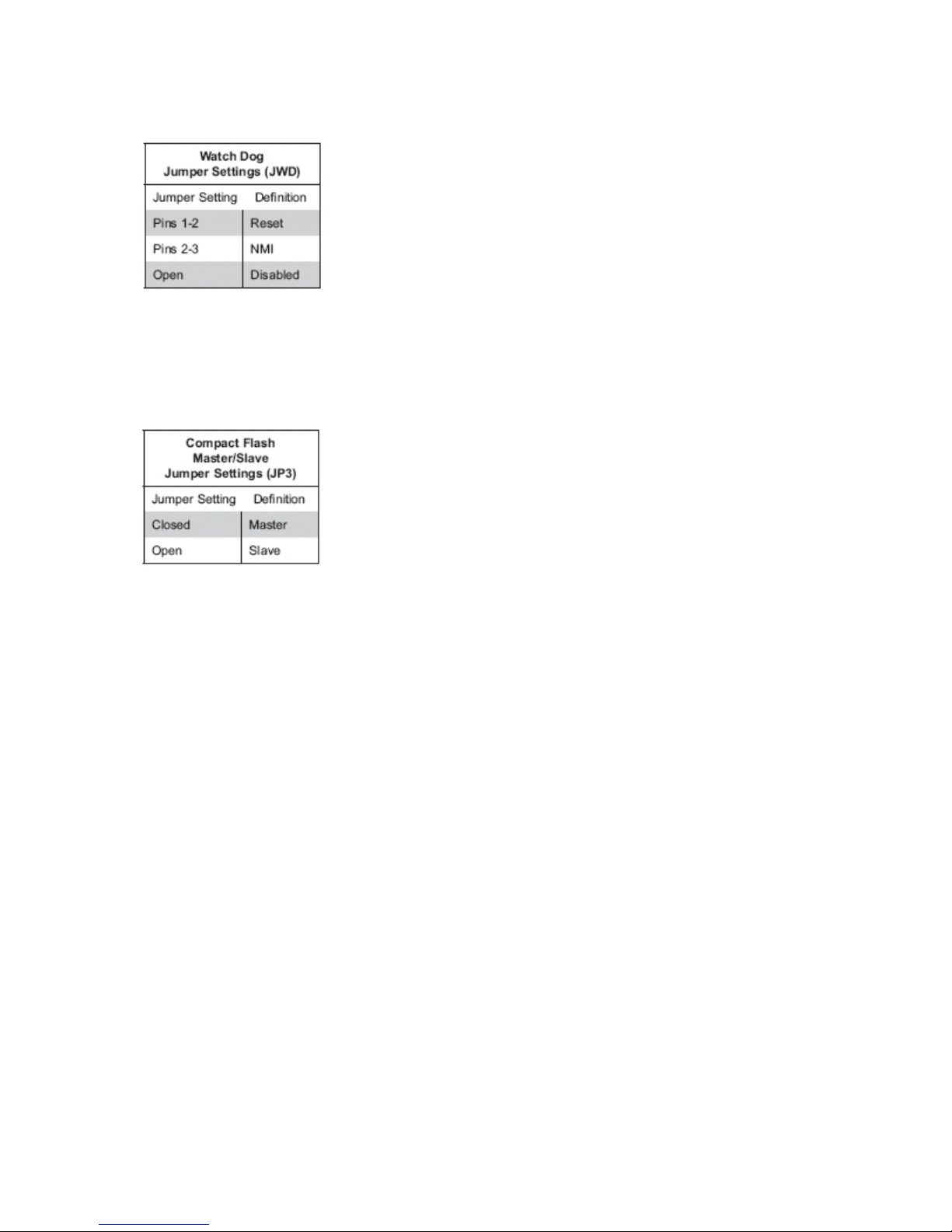
MPC Computers, LLC NetFRAME 1420
Watch Dog Jumper Settings
Compact Flash Master/Slave
The JP3 jumper allows you to assign either master or slave status to the compact fl ash card,
which plugs into the J4 connector.
Compact Flash Master/Slave Settings
Power Configuration Settings
This section describes features of your system board that deal with power and power settings.
Slow Blinking LED for Suspend-State Indicator
When the CPU goes into a suspend state, the chassis power LED will start blinking to indicate
that the CPU is in suspend mode. When the user presses any key, the CPU will wake-up and the
LED will automatically stop blinking and remain on.
BIOS Support for USB Keyboard
If the USB keyboard is the only keyboard in the system, it keyboard will function like a normal
keyboard during system boot-up.
Main Switch Override Mechanism
When an electrically compliant ATX power supply is used, the power button can function as a
system suspend button. When the user depresses the power button, the system will enter a
SoftOff state. The monitor will be suspended and the hard drive will spin down.
Depressing the power button again will cause the whole system to wake-up. During the SoftOff
state, the electrically compliant ATX power supply provides power to keep the required circuitry in
the system alive. In case the system malfunctions and you want to turn off the power, just
depress and hold the power button for 4 seconds. The power will turn off and no power will be
provided to the system board.
56
Page 57
MPC Computers, LLC NetFRAME 1420
Wake On-Ring (WOR)
Wake-up events can be triggered by a device such as the external modem ringing when the
system is in the SoftOff state. Note that external modem ring-on can only be used with an ATX
2.01 (or above) compliant power supply.
Wake-On-LAN (WOL)
Wake-On-LAN is defined as the ability of a management application to remotely power up a
computer that is powered off. Remote PC setup, up-dates and asset tracking can occur after
hours and on weekends so that daily LAN traffic is kept to a minimum and users are not
interrupted. The system board has a 3-pin header (WOL) to connect to the 3-pin header on a
Network Interface Card (NIC) that has WOL capability. Note that Wake-On-LAN can only be used
with an ATX 2.01 (or above) compliant power supply.
System Board Installation
The following sections provide information about installing your server's system board. To remove
the system board, follow the procedure in reverse order.
Caution: Read all precautions and instructions before installation.
The system board can be extremely sensitive to ESD and always requires careful
handling. After removing it from the chassis, place it component side up on a
nonconductive, static free surface to prevent shorting out the battery leads. If you place
the system board on a conductive surface, the battery leads may short out. If they do, this
will result in a loss of CMOS data and will drain the battery. Do NOT slide the system
board over any surface.
Touch a grounded metal object before removing the board from the antistatic bag.
Handle the board by its edges only; do not touch its components, peripheral chips,
memory modules, or gold contacts.
When handling chips or modules, avoid touching their pins.
Put the system board and peripherals back into their antistatic bags when not in use.
For grounding purposes, make sure your computer chassis provides excellent
conductivity between the power supply, the case, the mounting fasteners, and the system
board.
1. Accessing the Inside of the System
Remove the screws from the back lip of the top cover of the chassis, then pull the cover off.
2. Check Compatibility of System Board Ports and I/O Shield
Make sure that the I/O ports on the system board align properly with their respective holes in the
I/O shield at the back of the chassis.
3. Mounting the System Board onto the System Board Tray
Carefully mount the system board to the system board tray by aligning the board holes with the
raised metal standoffs that are visible in the chassis. Insert screws into all the mounting holes on
Page 58
MPC Computers, LLC NetFRAME 1420
your system board that line up with the standoffs and tighten until snug (if you screw them in too
tight, you might strip the threads). Metal screws provide an electrical contact to the system board
ground to provide a continuous ground for the system. Finish by replacing the top cover of the
chassis.
4. Connecting Cables
Now that the system board is installed, the next step is to connect the cables to the board. These
include the data (ribbon) cables for the peripherals and control panel and the power cables.
5. Connecting Data Cables
The ribbon cables used to transfer data from the peripheral devices have been carefully routed to
prevent them from blocking the flow of cooling air that moves through the system from front to
back. If you need to disconnect any of these cables, you should take care to keep them routed as
they were originally after reconnecting them (make sure the red wires connect to the pin 1
locations). The following data cables (with their locations noted) should be connected.
SATA drive cables (SATA#0, SATA#1)
Control Panel cable (JF1)
CD-ROM drive cable (J3)
Floppy drive cable (J27)
6. Connecting Power Cables
This system has a 24-pin primary power supply connector (JPW1) for connection to the
electrically compliant ATX power supply. In addition, there is an 8-pin secondary power connector
(JPW2) that also must be connected to your power supply.
7. Connecting the Control Panel
JF1 contains header pins for various front control panel connectors. All JF1 wires have been
bundled into a single ribbon cable to simplify this connection. Make sure the red wire plugs into
pin 1 as marked on the board. The other end connects to the Control Panel PCB board, located
just behind the system status LEDs on the chassis.
Software Installation
After all the hardware has been installed, you must first configure Intel's ICH7R SATA RAID*
before you install the Windows Operating System and other software drivers.
Introduction to Serial ATA and Parallel ATA
To configure the SATA RAID functions, you must first use the Intel ICH7R SATA RAID Utility
program to configure the RAID Level that you desire before installing the Windows XP/2000/2003
operating system and other software drivers. (The necessary drivers are all included on the
System Drivers and Documentation CD that came packaged with your system.) Note that the
current version of the ICH7R SATA RAID Utility can only support Windows XP/2000/2003
Operating Systems.
58
Page 59

MPC Computers, LLC NetFRAME 1420
Serial ATA (SATA)
Serial ATA (SATA) is a physical storage interface that uses a single cable with a minimum of four
wires to create a point-to-point connection between devices. It is a serial link, which supports
transfer rates up to 3Gbps. Because the serial cables used in SATA are thinner than the
traditional cables used in Parallel ATA (PATA), SATA systems have better airflow and can be
installed in smaller chassis than Parallel ATA. In addition, the cables used in PATA are limited to
a length of 40cm, while Serial ATA cables can be up to one meter in length. Overall, SATA
provides better functionality than PATA.
Introduction to Intel ICH7R Serial RAID
Located in the South Bridge of the E7230 Mukilteo chipset, the I/O Controller Hub (ICH7R)
provides the I/O subsystem with access to the rest of the system. It supports a 2-channel
UltraATA/100 Bus Master IDE controller (PATA) and four Serial ATA (SATA) ports. The ICH7R
supports the following PATA and SATA device configurations: Legacy mode and Native mode.
RAID Configurations
The following types of RAID configurations are supported:
RAID1 (Data Mirroring): an identical data image from one drive is copied to another drive. The
second drive must be the same size or larger than the first drive.
Intel Matrix Storage
The Intel Matrix Storage, supported by the ICH7R, allows the user to create RAID1 set by using
only two identical hard disk drives. The Intel Matrix Storage Technology creates two partitions on
each hard disk drive and generates a virtual RAID0 and RAID1 sets. It also allows you to change
the HDD partition size without any data.
Configuring BIOS settings for SATA RAID Functions (Native Mode)
1. Press the [Del] key during system bootup to enter the BIOS Setup Utility. Note: If it is the
first time powering on the system, we recommend you load the Optimized Default
Settings. If you have already done so, please skip to Step 3.
2. Use the arrow keys to select the Exit Settings. Once in the Exit settings, Scroll down to
select Load Optimized Default Settings and press the [Enter] key. Select OK to confirm
the selection. Press the [Enter] key to load the default settings for the BIOS.
3. Use the arrow keys to select the Main section in BIOS.
4. Scroll down to SATA Control Mode and press the [Enter] key to select Enhanced.
5. Scroll down to SATA RAID Enabled and press [Enter]. Then, select Enabled.
6. Scroll down to Exit. Select Save and Exit from the Exit menu. Press the [Enter] key to
save the changes and exit the BIOS.
7. Once you've exited the BIOS Utility, the system will re-boot.
8. During the system boot-up, press the [Ctrl] and [I] keys simultaneously to run the Intel
RAID Configuration Utility when prompted by the following message: "Press <Ctrl> <I>
for Intel RAID Configuration Utility."
Page 60
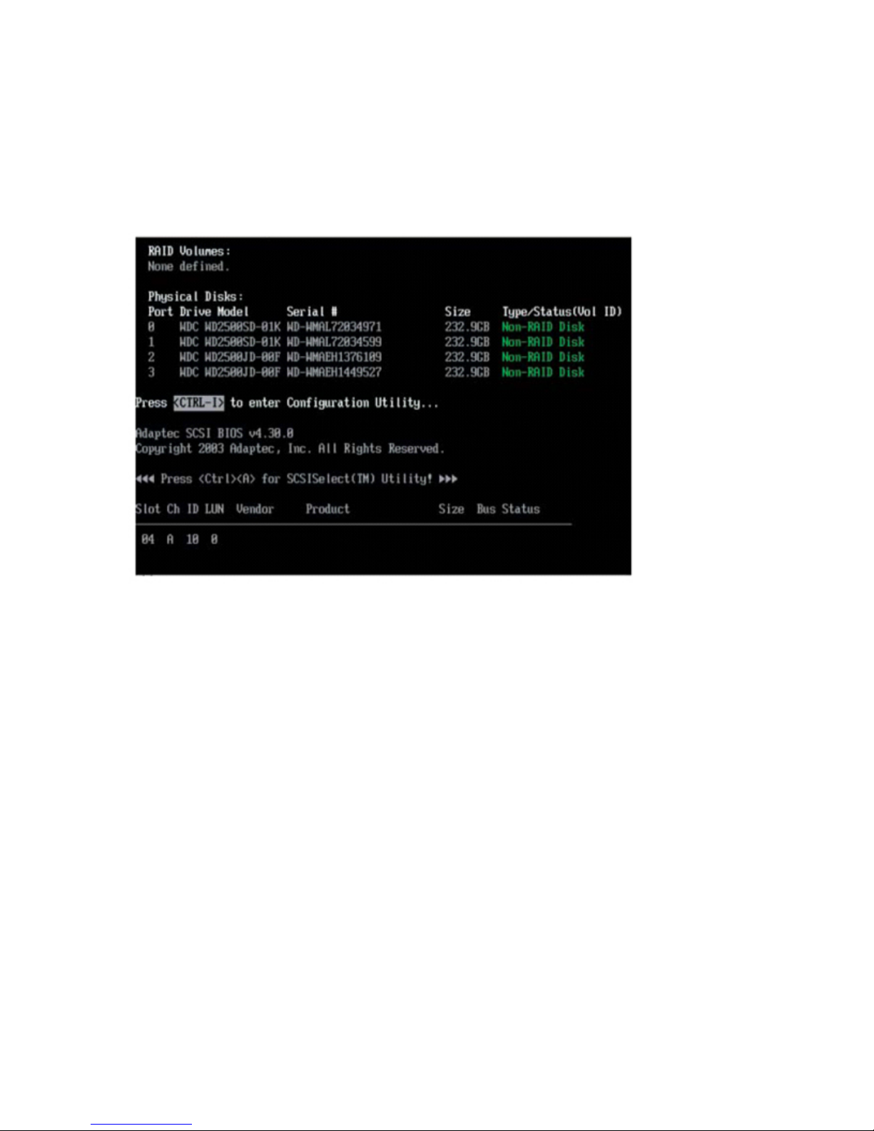
MPC Computers, LLC NetFRAME 1420
Using the Intel ICH7R SATA RAID Utility Program
Creating, Deleting and Resetting RAID Volumes:
1. After the system exits from the BIOS Setup Utility, the system will automatically reboot.
The following screen appears after Power-On Self Test.
RAID Volumes Screen
2. When you see the above screen, press the [Ctrl] and the [I] keys simultaneously to have
the main menu of the SATA RAID Utility appear.
Creating a RAID 1 Volume:
1. Select Create RAID Volume from the main menu and press the [Enter] key. The
following screen will appear:
60
Page 61
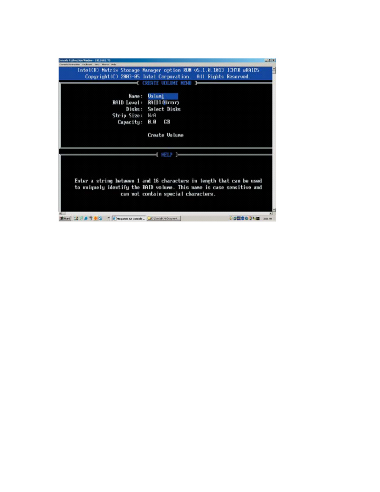
MPC Computers, LLC NetFRAME 1420
RAID 1 Volume Screen
2. Specify a name for the RAID 1 set and press the [Tab] key or the [Enter] key to go to the
next field. (You can use the [Esc] key to select the previous menu.)
3. When RAID Level item is highlighted, press the [Up Arrow], [Down Arrow] keys to select
RAID 1 (Mirror) and press [Enter].
4. When the Capacity item is highlighted, enter your RAID volume capacity and press
[Enter]. The default setting is the maximum capacity allowed.
5. Press [Enter] when the Create Volume item is highlighted. A warning message displays.
6. When asked "Are you sure you want to create this volume (Y/N), press "Y" to create the
RAID volume, or type "N" to go back to the Create Volume menu.
Deleting RAID Volume:
Warning: Be sure to back up your data before deleting a RAID set. You will lose all data on
the disk drives when deleting a RAID set.
1. From the main menu, select item 2-Delete RAID Volume, and press [Enter].
2. Use the [Up Arrow], [Down Arrow] keys to select the RAID set you want to delete and
press [Del]. A Warning message displays.
3. When asked "Are you sure you want to delete this volume (Y/N), press "Y" to delete the
RAID volume, or type "N" to go back to the Delete Volume menu.
Page 62
MPC Computers, LLC NetFRAME 1420
BIOS Setup
This section describes the Basic Input/Output System (BIOS) Setup options. Use Setup to
change the server configuration defaults. You can run Setup with or without an operating system
being present. Setup stores most of the configuration values in battery-backed CMOS; the rest of
the values are stored in flash memory. The configuration values take effect when you boot the
server. Power-on self test (POST) uses these values to configure the hardware; if the values and
the actual hardware do not agree, POST generates an error message. You must then run BIOS
Setup to specify the correct configuration.
System BIOS
The BIOS is the Basic Input Output System. The Phoenix BIOS flash chip stores the system
parameters, such type of disk drives, video displays, etc. in the CMOS. The CMOS memory
requires very little electrical power. When the computer is turned off, a backup battery provides
power to the BIOS flash chip, enabling it to retain system parameters. Each time the computer is
powered-on the computer is configured with the values stored in the BIOS ROM by the system
BIOS, which gains control at boot-up.
Starting Setup
Normally, the only visible POST (Power On Self Test) routine is the memory test. As the memory
is being tested, press the [Delete] key to enter the main menu of the BIOS Setup utility. From the
main menu, you can access the other setup screens, such as the Chipset and Power menus.
Main BIOS Setup gives detailed descriptions of each parameter setting in the Setup utility.
The following sections provide more information about BIOS Setup.
Changing the Configuration Data
Running Setup
Main Setup
Advanced Setup
Security
Boot
Exit
Changing the Configuration Data
The CMOS information that determines the system parameters may be changed by entering the
BIOS Setup utility. This Setup utility can be accessed by pressing [Delete] at the appropriate time
during system boot.
Running Setup
The BIOS setup options described in this section are selected by choosing the appropriate text
from the Main BIOS Setup screen. All displayed text is described in this section, although the
screen display is often all you need to understand how to set the options.
While the BIOS is in control, the Setup program can be activated in one of two ways:
1. By pressing [Delete] immediately after turning the system on; or
62
Page 63
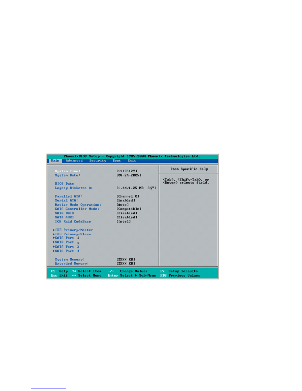
MPC Computers, LLC NetFRAME 1420
2. When the following message appears briefly at the bottom of the screen during the POST
(Power On Self-Test), press the [Delete] key to activate the Main Setup Menu.
Main Setup
All Main setup options are described in this section.
Use the [Up] [Down] arrow keys or the [Tab] key to move among the different settings in the
above menu.
Press the [Esc] key to exit the CMOS Setup Menu and use the [Left] [Right] arrow keys to enter
the other categories of BIOS settings.
Main Menu
The Main menu is used to report processor and memory information and to configure the system
date, system time, and Setup languages.
Main Menu
System Time
To set the system date and time, key in the correct information in the appropriate fields. Then
press the [Enter] key to save the data.
System Date
Using the arrow keys, highlight the month, day and year fields and enter the correct data. Press
the [Enter] key to save the data.
BIOS Date
This feature allows BIOS to automatically display the BIOS date.
Page 64

MPC Computers, LLC NetFRAME 1420
Legacy Diskette A
This setting allows the user to set the type of floppy disk drive installed as diskette A. The options
are Disabled, 360Kb 5.25 in, 1.2MB 5.25 in, 720Kb 3.5 in, 1.44/1.25MB, 3.5 in and 2.88MB 3.5 in.
Parallel ATA
This setting allows the user to enable or disable the function of Parallel ATA. The options are
Disabled and Enabled.
Serial ATA
This setting allows the user to enable or disable the function of Serial ATA. The options are
Disabled and Enabled.
Native Mode Operation
Select the native mode for ATA. The options are: Serial ATA and Auto.
SATA Controller Mode
Select Compatible to allow the SATA and PATA drives to be auto-detected and placed in the
Legacy Mode. Select Enhanced to allow the SATA and PATA drives to be auto-detected and
placed in the Native IDE Mode. Note: The Enhanced mode is supported by the Windows 2000
OS or a later version.
When the SATA Controller Mode is set to "Enhanced", the following items will display:
Serial ATA (SATA) RAID
Select Enable to enable Serial ATA RAID Functions. (*For the Windows OS environment, use the
RAID driver if this feature is set to Enabled. If set to Disabled, use the Non-RAID driver. When
this feature--SATA RAID is set to Enabled, the next item-"SATA AHCI Enable" will not be
available.) The options are Enabled and Disabled (*Default). *If this feature is set to "Enhanced",
the following feature will be available:
SATA AHCI
Select Enable to enable the function of Serial ATA Advanced Host Interface. (*Take caution when
using this function. This feature is for advanced programmers only.) The options are Enabled and
Disabled.
ICH RAID CodeBase
Select Intel to enable Intel's ICH RAID Controller for the Windows OS. Select Adaptec to enable
Adaptec's RAID Controller for the Linux OS. The options are Intel and Adaptec.
Primary IDE Master/Slave, Secondary IDE Master/Slave, or Primary IDE
Master/Slave, SATA Port 1, SATA Port 2,SATA Port 3, SATA Port 4
These settings allow the user to set the parameters of Primary IDE Master/Slave and Secondary
IDE Master/Slave slots. Hit <Enter> to activate the following sub-menu screen for detailed options
of these items. Set the correct configurations accordingly.
64
Page 65
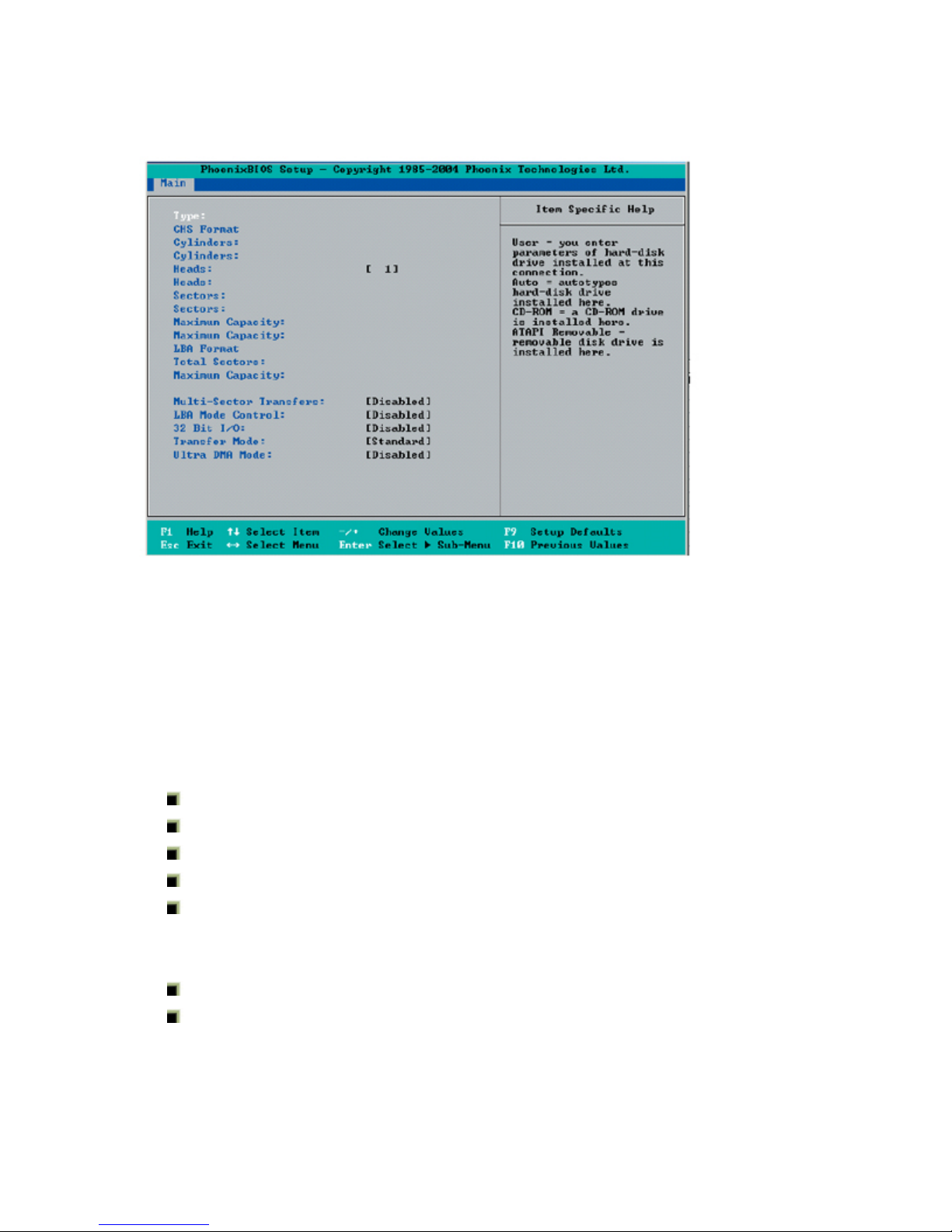
MPC Computers, LLC NetFRAME 1420
Primary IDE Master/Slave, Secondary IDE Master/Slave, or Primary IDE Master/Slave,
SATA Port 1, SATA Port 2,SATA Port 3, SATA Port 4
Type
Selects the type of IDE hard drive. The options are Auto, (which allows BIOS to automatically
determine the hard drive's capacity, number of heads, etc.), a number from 1-39 to select a
predetermined type of hard drive, CDROM and ATAPI Removable. The option- "User" will allow
the user to enter the parameters of the HDD installed at this connection. The option-"Auto" will
allow BIOS to automatically configure the parameters of the HDD installed at the connection.
Choose the option 1-39 to select a predetermined HDD type. Select CDROM if a CDROM drive is
installed. Select ATAPI if a removable disk drive is installed.
CHS Format
The following items will be displayed by the BIOS:
TYPE: This item displays the type of CPU.
Cylinders: This item indicates the status of Cylinders.
Headers: This item indicates the number of headers.
Sectors: This item displays the number of sectors.
Maximum Capacity: This item displays the maximum storage capacity of the system.
LBA Format
The following items will be displayed by the BIOS:
Total Sectors: This item displays the number of total sectors available in the LBA Format.
Maximum Capacity: This item displays the maximum capacity in the LBA Format.
Multi-Sector Transfer
This item allows the user to specify the number of sectors per block to be used in multi-sector
transfer. The options are Disabled, 4 Sectors, 8 Sectors and 16 Sectors.
Page 66
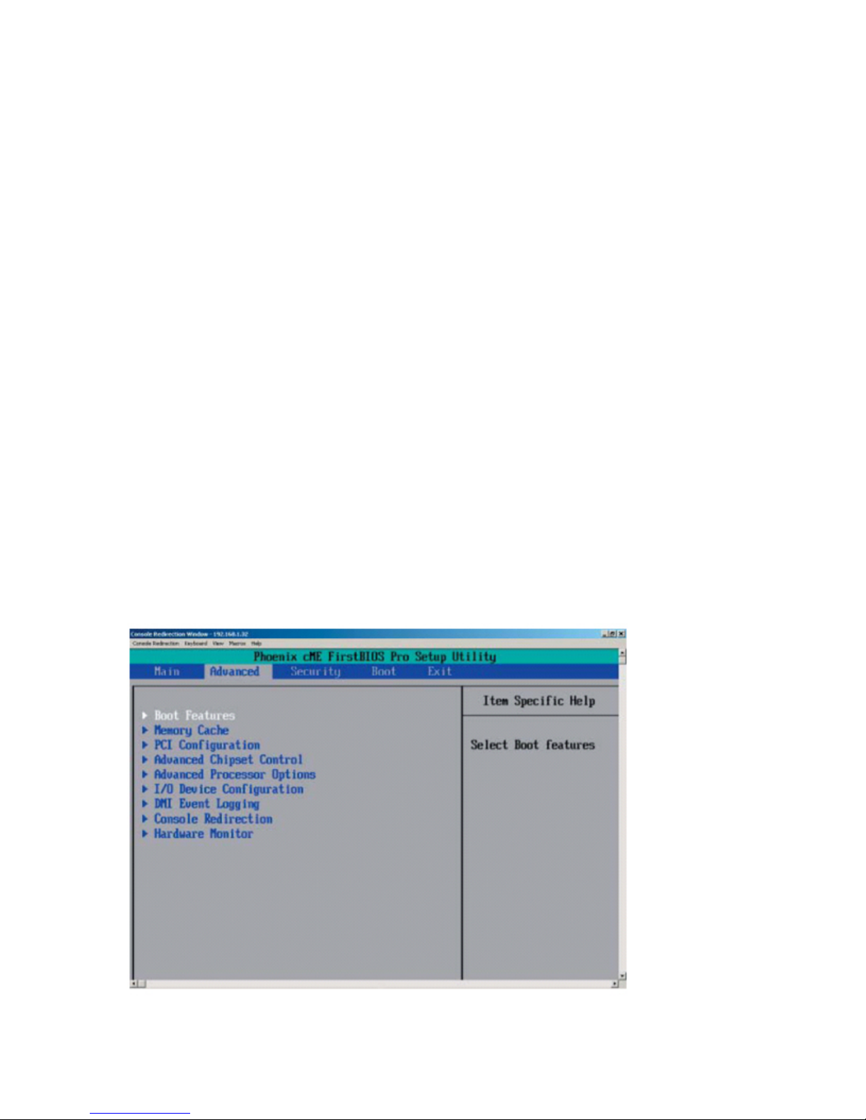
MPC Computers, LLC NetFRAME 1420
LBA Mode Control
This item determines if the BIOS will access the Primary IDE Master Device via the LBA mode.
The options are Enabled and Disabled.
32 Bit I/O
This feature allows the user to enable or disable the function of 32-bit data transfer. The options
are Enabled and Disabled.
Transfer Mode
This feature allows the user to select the transfer mode. The options are Standard, Fast PIO1,
Fast PIO2, Fast PIO3, Fast PIO4, FPIO3/DMA1 and FPIO4/DMA2.
Ultra DMA Mode
This feature allows the user to select the Ultra DMA Mode. The options are Disabled, Mode 0,
Mode 1, Mode 2, Mode 3, Mode 4 and Mode 5.
System Memory
This display informs you how much system memory is detected in the system.
Extended Memory
This display informs you how much extended memory is detected in the system.
Advanced Setup
Choose Advanced from the Setup Utility main menu with the arrow keys. You should see the
following display. The items with a triangle beside them have sub menus that can be accessed by
highlighting the item and pressing [Enter]. Options for settings are displayed by highlighting the
setting option using the arrow keys and pressing [Enter]. All Advanced BIOS Setup options are
described in this section.
Advanced Menu
66
Page 67

MPC Computers, LLC NetFRAME 1420
Boot Features
Access the submenu to make changes to the following settings.
Quick Boot Mode
If enabled, this feature will speed up the POST (Power On Self Test) routine by skipping certain
tests after the computer is turned on. The settings are Enabled and Disabled. If Disabled, the
POST routine will run at normal speed.
Quiet Boot
Set to Enabled to display the Diagnostic Screen during POST. The settings are Enabled and
Disabled.
ACPI Mode
Use the setting to determine if you want to employ ACPI (Advanced Configuration and Power
Interface) power management on your system. The options are Yes and No.
Power Button Behavior
If set to Instant-Off, the system will power off immediately as soon as the user hits the power
button. If set to 4-sec., the system will power off when the user presses the power button for 4
seconds or longer. The options are instant-off and 4-sec override.
Resume On Modem Ring
Select On to "wake your system up" when an incoming call is received by your modem. The
options are On and Off.
Power Loss Control
This setting allows you to choose how the system will react when power returns after an
unexpected loss of power. The options are Last State, Stay off, and Power On.
Watch Dog
If enabled, this option will automatically reset the system if the system is not active for more than
5 minutes. The options are Enabled and Disabled.
Summary Screen
This setting allows you to Enable or Disable the summary screen which displays the system
configuration during bootup.
Memory Cache
Cache Memory
Set to enabled to set the state of Cache Memory. The options are Enabled and Disabled.
Cache System BIOS Area
This setting allows you to designate a reserve area in the system memory to be used as a
System BIOS buffer to allow the BIOS write (cache) its data into this reserved memory area.
Select "Write Protect" to enable this function, and this area will be reserved for BIOS ROM
access only. Select "Uncached" to disable this function and make this area available for other
devices.
Cache Video BIOS Area
This setting allows you to designate a reserve area in the system memory to be used as a Video
BIOS buffer to allow the BIOS write (cache) its data into this reserved memory area. Select "Write
Page 68

MPC Computers, LLC NetFRAME 1420
Protect" to enable the function and this area will be reserved for Video BIOS ROM access only.
Select "Uncached" to disable this function and make this area available for other devices.
Cache Base 0-512K
If enabled, this feature will allow the data stored in the base memory area: block 0-512K to be
cached (written) into a buffer, a storage area in the Static DRM (SDROM) or to be written into L1,
L2 cache inside the CPU to speed up CPU operations. Select "Uncached" to disable this function.
Select "Write Through" to allow data to be cached into the buffer and written into the system
memory at the same time. Select "Write Protect" to prevent data from being written into the base
memory area of Block 0-512K. Select "Write Back" to allow CPU to write data back directly from
the buffer without writing data to the System Memory for fast CPU data processing and operation.
The options are "Uncached", "Write Through", "Write Protect", and "Write Back".
Cache Base 512K-640K
If enabled, this feature will allow the data stored in the base memory area: block 512K-640K to be
cached (written) into a buffer, a storage area in the Static DRM (SDROM) or to be written into L1,
L2 cache inside the CPU to speed up CPU operations. Select "Uncached" to disable this function.
Select "Write Through" to allow data to be cached into the buffer and written into the system
memory at the same time. Select "Write Protect" to prevent data from being written into the base
memory area of Block 512K-640K. Select "Write Back" to allow CPU to write data back directly
from the buffer without writing data to the System Memory for fast CPU data processing and
operation. The options are "Uncached", "Write Through", "Write Protect", and "Write Back".
Cache Extended Memory
If enabled, this feature will allow the data stored in the extended memory area to be cached
(written) into a buffer, a storage area in the L1, L2, L3 cache inside the CPU to speed up CPU
operations. Select "Uncached" to disable this function. Select "Write Through" to allow data to be
cached into the buffer and written into the system memory at the same time. Select "Write
Protect" to prevent data from being written into the extended memory area. Select "Write Back" to
allow the CPU to write data back directly from the buffer without writing data to the System
Memory for fast CPU data processing and operation. The options are "Uncached", "Write
Through", "Write Protect", and "Write Back".
Discrete MTRR Allocation
If enabled, MTRRs (-Memory Type Range Registers) are configured as distinct, separate units
and cannot be overlapped. If enabled, the user can achieve better graphic effects when using a
Linux graphic driver that requires the write combining configuration with 4GB or more memory.
The options are Enabled and Disabled.
PCI Configuration
Access the submenu to make changes to the following settings for PCI devices.
Onboard GLAN1/GLAN2 (Gigabit- LAN)
Enabling this option provides the capability to boot from GLAN. The options are Disabled and
Enabled.
Reset Configuration Data
If set to Yes, this setting clears the Extended System Configuration Data- (ESCD) area. The
options are Yes and No.
Frequency for PCIX
This option allows the user to change the bus frequency for the devices installed in the slots
indicated. The options are Auto, PCI 33 MHz, PCI 66 MHz, PCI-X 66 MHz, PCI-X 100 MHz, and
PCI-X 133 MHz.
68
Page 69

MPC Computers, LLC NetFRAME 1420
Slot 1 PCI 32-bit/Slot 2 PCI-X 133 MHz
Access the submenu for each of the settings above to make changes to the following:
Option ROM Scan
When enabled, this setting will initialize the device expansion ROM. The options are Enabled and
Disabled.
Enable Master
This setting allows you to enable the selected device as the PCI bus master. The options are
Enabled and Disabled.
Latency Timer
This setting allows you to set the clock rate for Bus Master. A high-priority, high-throughout
device may benefit from a greater Clock rate. The options are Default, 0020h, 0040h, 0060h,
0080h, 00A0h, 00C0h, and 00E0h. For Unix, Novell and other Operating Systems, please select
the option: other. If a drive fails after the installation of a new software , you might want to change
this setting and try again. Different OS requires different Bus Master clock rate.
Large Disk Access Mode
This setting determines how large hard drives are to be accessed. The options are DOS or Other
(for Unix, Novelle NetWare and other operating systems).
Advanced Chipset Control
Access the submenu to make changes to the following settings.
Clock Spectrum Feature
If "Enabled", BIOS will monitor the level of Electromagnetic Interference caused by the
components and will attempt to decrease the interference whenever needed. The options are
Enabled and Disabled.
ECC Conditions
This setting specifies the ECC Error conditions that will be treated as "ECC Error Events" by the
system. The options are None, Single Bit, Multiple Bit and Both. Note: This item is available when
it is supported by the memory.
ECC Error Handler
This setting allows you to select the type of interrupt to be activated as a result of an ECC error.
The options are None, NMI (Non-Maskable Interrupt), SMI (System Management Interrupt) and
SCI (System Control Interrupt.) Note: This item is available when it is supported by the memory.
Onboard GLANs
This feature allows the user to enable this function to allow the BIOS to disable Gigabit LAN. The
options are: Enabled and Disabled.
Route Port 80h Cycles to
This feature allows the user to decide which bus to send the debug information to. The options
are PCI, LPC and Disabled.
USB Function
If set to Enabled to enable the USB function when the user keys in a value to a USB item. The
options are Enabled and Disabled.
Page 70

MPC Computers, LLC NetFRAME 1420
Legacy USB Support
This setting allows you to enable support for the Legacy USB devices. The settings are Enabled
and Disabled.
Caution: Take caution when changing the Advanced settings. Incorrect values entered
may cause system malfunction. Also, a very high DRAM frequency or incorrect DRAM
timing may cause system instability. When this occurs, revert to the default setting.
Advanced Processor Options
Access the submenu to make changes to the following settings:
CPU Speed
The feature allows the BIOS to display the CPU Speed.
Hyper-threading (*Available when supported by the CPU.)
This setting allows you to Enable or Disable the function of hyper-threading. Enabling hyperthreading results in increased CPU performance. (Applicable for XP systems.)
Single Logical Processor Mode (*Available when supported by the CPU.)
This feature allows the user to select the Processor Operation Mode. Set to Disabled to allow the
processor to operate in the "single core" mode. Set to Enabled to allow the processor to operate
in the "multi-core" (dual-core) mode.
Machine Checking
Set to Enabled to allow the operating system to debug a system crash after a reset. The options
are Disabled and Enabled.
L3 Cache (*Available when supported by the CPU.)
Set to Enabled to enable L3 cache in the CPU to enhance system performance. The options are
Disabled and Enabled.
Thermal Management 2 (*Available when supported by the CPU.)
If enabled, this feature allows you to select between Thermal Manager 1 and Thermal Manager 2.
Set to Disable to activate the function of TM1, allowing the CPU to regulate its power
consumption based upon the modulation of the CPU Internal clock when the CPU temperature
reaches a pre-defined overheat threshold. Set to Enable to activate the function of TM2, which
will allow the CPU to reduce its power consumption by lowering the CPU frequency and the CPU
voltage when the CPU temperature reaches a pre-defined overheat threshold. Note: please refer
to Intel's web site for detailed information.
Adjacent Cache Line Prefetch
The CPU fetches the cache line for 64 bytes if Disabled. The CPU fetches both cache lines for
128 bytes as comprised if Enabled.
C1 Enhanced Mode (*Available when supported by the CPU.)
Set to Enabled to enable the Enhanced Halt State. The options are Enabled and Disabled. Note:
please refer to Intel's web site for detailed information.
No Execute Mode Memory Protection
Enable this feature to enable the functionality of Execute Disable Bit and allow the processor to
classify areas in the memory where an application code can execute and where it cannot, and
thus preventing a worm or a virus from inserting and creating a flood of codes that will overwhelm
the processor or damage the system during an attack. Note: this feature is available when your
OS and your CPU support the function of Execute Disable Bit. The options are Disabled and
70
Page 71

MPC Computers, LLC NetFRAME 1420
Enabled. Note: For more information regarding hardware/software support for this function,
please refer to Intel's and Microsoft's web sites.
Processor Power Management (*Available when supported by the CPU.)
This feature allows the user to determine the processor power management mode. If set to C
States only, the processor power will be controlled through CPU power states in the ACPI setting.
Select "GV1/GV3 only" to enable the function of DBS (Demand Based Switching) which will allow
the user to configure CPU power management in the OS. If set to Disabled, C States and
GV1/GV3 are disabled. If set to Enabled, C States and GV1/GV3 are Enabled. Note: please refer
to Intel's web site for detailed information.
I/O Device Configuration
Access the submenu to make changes to the following settings.
KBC Clock input
This setting allows you to set the clock frequency for the Keyboard Clock. The options are 6MHz,
8MHz, 12 MHz and 16MHz.
Serial Port A
This setting allows you to decide how Serial Port A is controlled. The options are Enabled (user
defined), Disabled, and Auto (BIOS- or OS- controlled).
Base I/O Address
Select the base I/O address for Serial Port A. The options are 3F8, 2F8, 3E8 and 2E8.
Interrupt
Set the Interrupt for Serial Port A. The options are IRQ3 and IRQ4.
Serial Port B
This setting allows you to decide how Serial Port B is controlled. The options are Enabled (user
defined), Disabled, and Auto (BIOS- or OS- controlled).
Mode
This feature allows the user to set the mode for Serial Port B. The options are Normal and IR.
Base I/O Address
Select the base I/O address for Serial Port B. The options are 3F8, 2F8, 3E8 and 2E8.
Interrupt
Set the Interrupt for Serial Port B. The options are IRQ3 and IRQ4.
Parallel Port
This setting allows you to assign control of the Parallel Port. The options are Enabled (user
defined), Disabled, and Auto (BIOS- or OS- controlled).
Base I/O Address
Select the base I/O address for the Parallel Port. The options are 378, 278, and 3BC.
Interrupt
Set the Interrupt for the Parallel Port. The options are IRQ5 and IRQ7.
Mode
This feature allows the user to set the mode for the Parallel Port. The options are Output Only, BiDirectional, EPP and ECP.
Page 72

MPC Computers, LLC NetFRAME 1420
DMA Channel
This feature allows the user to select the DMA Channel for the Parallel Port. The options are
DMA1 and DMA3.
Floppy Disk Controller
This setting allows you to assign control of the floppy disk controller. The options are Enabled
(user defined), Disabled, and Auto (BIOS and OS controlled).
Base I/O Address
Select the base I/O address for the parallel port. The options are Primary and Secondary.
DMI Event Logging
Access the submenu to make changes to the following settings.
Event Log Validity
This is a display to inform you of the event log validity. It is not a setting.
Event Log Capacity
This is a display to inform you of the event log capacity. It is not a setting.
View DMI Event Log
Highlight this item and press [Enter] to view the contents of the event log.
Event Logging
This setting allows you to Enable or Disable event logging.
ECC Event Logging
This setting allows you to Enable or Disable ECC event logging.
Mark DMI Events as Read
Highlight this item and press [Enter] to mark the DMI events as read.
Clear All DMI Event Logs
Select Yes and press [Enter] to clear all DMI event logs. The options are Yes and No.
Console Redirection
Access the submenu to make changes to the following settings.
COM Port Address
This item allows you to specify to redirect the console to Onboard COM A or Onboard COM B.
This setting can also be Disabled.
BAUD Rate
This item allows you to select the BAUD rate for console redirection. The options are 300, 1200,
2400, 9600, 19.2K, 38.4K, 57.6K and 115.2K.
Console Type
This item allows you to choose from the available options to select the console type for console
redirection. The options are VT100, VT100,8bit, PC-ANSI, 7bit, PC ANSI, VT100+, VT-UTF8.
Flow Control
72
Page 73
MPC Computers, LLC NetFRAME 1420
This item allows you to choose from the available options to select the flow control for console
redirection. The options are: None, XON/XOFF, and CTS/RTS.
Console Connection
This item allows you to decide how Console Redirection is to be connected: either Direct or Via
Modem.
Continue CR after POST
Choose whether to continue with console redirection after the POST routine. The options are On
and Off.
Hardware Monitoring
CPU Temperature Threshold
This option allows the user to set a CPU temperature threshold that will activate the alarm system
when the CPU temperature reaches this pre-set temperature threshold. The options are 75C,
80C, 85C and 90C. Highlight this and press [Enter] to see the data for the following items:
CPU Temperature
System Temperature
Fan 1 Speed - FAN 5 Speed: If the feature of Auto Fan Control is enabled, the BIOS will
automatically display the status of the fans indicated in this item.
Fan Speed Control Modes
This feature allows the user to decide how the system controls the speeds of the onboard fans. If
the option is set to "3-pin fan", the fan speed is controlled based upon the CPU die temperature.
When the CPU die temperature is higher, the fan speed will be higher as well. If the option is set
to "4-pin", the fan speed will be controlled by the Thermal Management Settings pre-configured
by the user at this feature. Select "3-pin" if your chassis came with 3-pin fan headers. Select "4pin" if your chassis came with 4-pin fan headers. Select "Disable" to disable the fan speed control
function to allow the onboard fans to run at the full speed (12V) at all time. The Options are: 1.
Disable (Full Speed at 12V), 2. Optimized Server w/3-pin, and 3. Optimized Server w/4-pin.
The Voltage status of the following items will be displayed:
VcoreA
1.5V
Vin0 (3.3V)
Vin1 (5V)
Vin2 (-12V)
Vin3 (12V)
5V Standby
Page 74
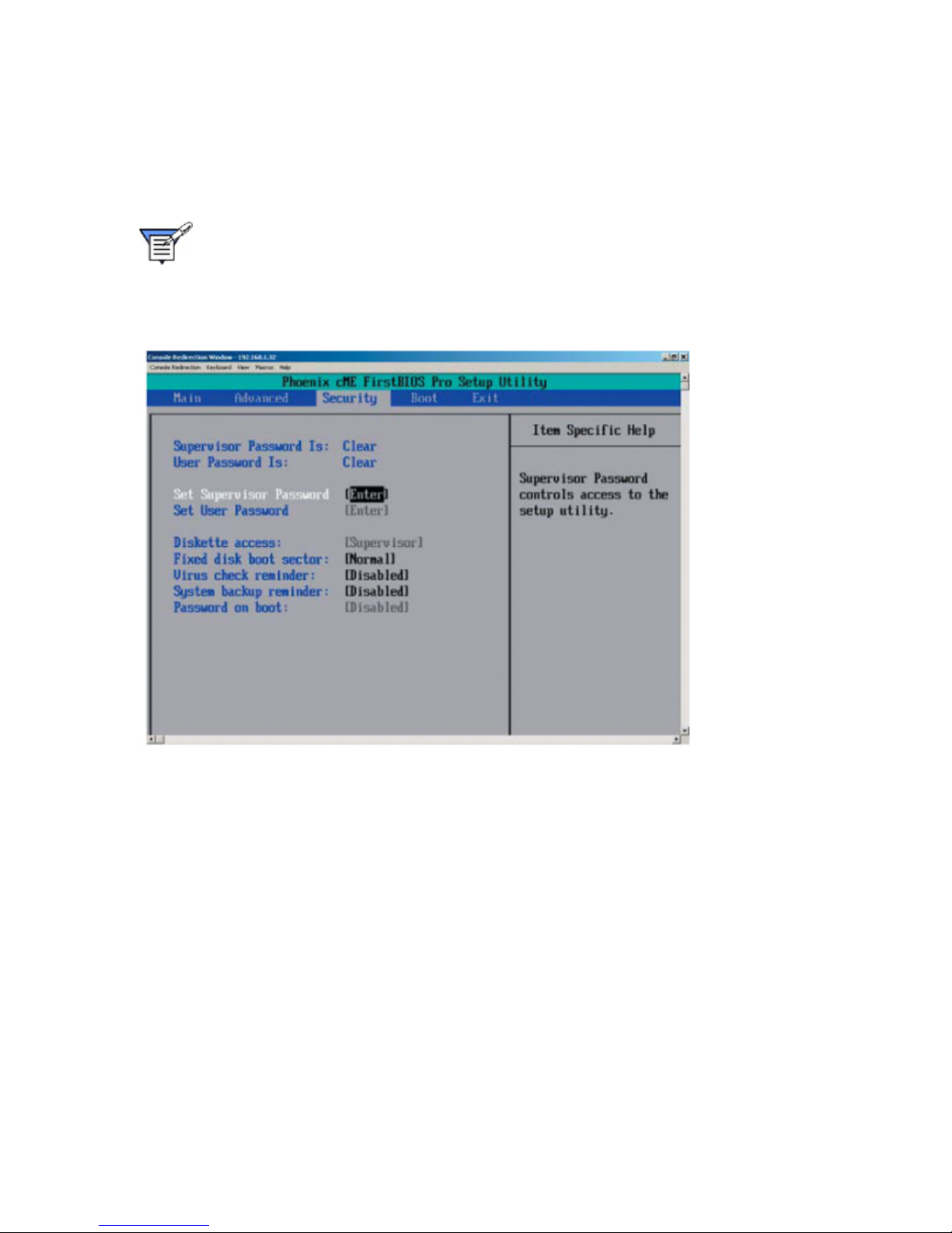
MPC Computers, LLC NetFRAME 1420
Security
The Security menu is used to set passwords and security features.
Choose Security from the main menu with the Left/Right arrow keys and press [Enter].
Note: Depending on your system's configuration and BIOS revision, your system's
defaults may be different from the defaults in the table below. Also, certain values
or options shown in the table may not be present in your system's BIOS. This BIOS
section is for reference only.
Security Menu
Supervisor Password Is:
This displays whether a supervisor password has been entered for the system. Clear means such
a password has not been used and Set means a supervisor password has been entered for the
system.
User Password Is:
This displays whether a user password has been entered for the system. Clear means such a
password has not been used and Set means a user password has been entered for the system.
Set Supervisor Password
When the item "Set Supervisor Password" is highlighted, press the [Enter] key. When prompted,
type the Supervisor's password in the dialogue box to set or to change supervisor's password,
which allows access to BIOS.
Set User Password
When the item "Set User Password" is highlighted, press the [Enter] key. When prompted, type
the user's password in the dialogue box to set or to change the user's password, which allows
access to the system at boot-up.
74
Page 75
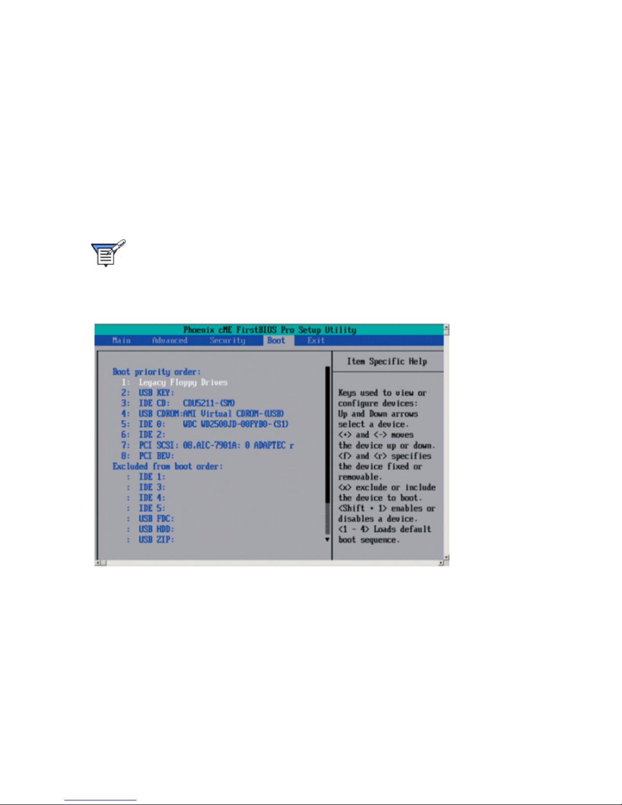
MPC Computers, LLC NetFRAME 1420
Fixed Disk Boot Sector
This setting may offer some protection against viruses when set to Write Protect, which protects
the boot sector on the hard drive from having a virus written to it. The other option is Normal.
Password on Boot
This setting allows you to require a password to be entered when the system boots up. The
options are Enabled (password required) and Disabled (password not required).
Boot
The Boot menu is used to set boot features and the boot sequence.
Choose Boot from the main menu with the Left/Right arrow keys and press [Enter].
Note: Depending on your system's configuration and BIOS revision, your system's
defaults may be different from the defaults in the table below. Also, certain values
or options shown in the table may not be present in your system's BIOS. This BIOS
section is for reference only.
Boot Menu
Boot Priority Order/Excluded from Boot Order
Use the Up and Down Arrow Keys to select a device. Use [+] and [-] keys to move the device up
or down. Use the [f] key or the [r] key to specify the devices. You can also use the keys indicated
above to specify the priority of the boot order for a device or move a item from the category of
"Excluded from Boot Order" to the category of "Boot Priority Order" and vise versa. Please refer
to the window of "Item Specific Help" for details.
Page 76
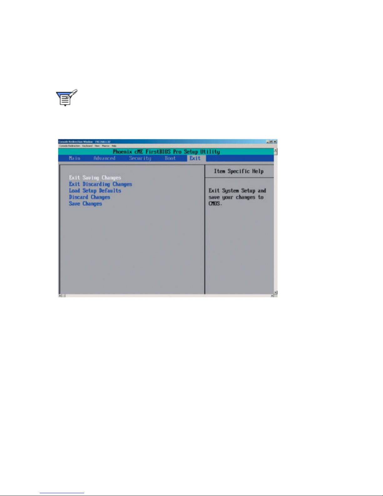
MPC Computers, LLC NetFRAME 1420
Exit
The Exit menu is used to exit Setup, save changes, and load and save defaults.
Choose Exit from the main menu with the Left/Right arrow keys and press [Enter].
Note: Depending on your system's configuration and BIOS revision, your system's
defaults may be different from the defaults in the table below. Also, certain values
or options shown in the table may not be present in your system's BIOS. This BIOS
section is for reference only.
Exit Menu
Exit Saving Changes
Highlight this item and press [Enter] to save any changes you made and to exit the BIOS Setup
utility.
Exit Discarding Changes
Highlight this item and press [Enter] to exit the BIOS Setup utility without saving any changes
you may have made.
Load Setup Defaults
Highlight this item and press [Enter] to load the default settings for all items in the BIOS Setup.
These are the safest settings to use.
Discard Changes
Highlight this item and press [Enter] to discard (cancel) any changes you made. You will remain
in the Setup utility.
Save Changes
Highlight this item and press [Enter] to save any changes you made. You will remain in the Setup
utility.
76
Page 77
MPC Computers, LLC NetFRAME 1420
Troubleshooting
In the unlikely event you encounter problems running your system, this section will help you
identify possible problem areas. If you are unable to resolve a problem using this section, please
contact technical support.
The following information is covered in this Troubleshooting section:
System Board Problems
BIOS POST Messages
Diagnostic Testing Preparation
Initial System Startup Problems
New Application Software Problems
Problems after the System Has Been Running
FAQs
Specific Problems
System Board Problems
Troubleshooting Procedures
Use the following procedures to troubleshoot your system. Always disconnect the AC power cord
before adding, changing or installing any hardware components.
Before Power On
1. Check that the Standby PWR LED (LE1) is not lit. Note: If LE1 is on, it indicates that
Standby PWR is on. Be sure to turn off the power supply before installing or removing the
components.
2. Make sure the 8-pin 12v power connector at JPW2 is connected.
3. Make sure that no short circuits exist between the system board and chassis.
4. Disconnect all ribbon/wire cables from the system board, including those for the keyboard
and mouse.
5. Remove all add-on cards.
6. Install a CPU and heatsink (be sure that it is fully seated,) and then, connect the chassis
speaker and the power LED to the system board. Check all jumper settings as well.
7. Make sure to use the correct type of CMOS battery. Do not install the CMOS battery
upside down to avoid possible explosion.
No Power
1. Make sure that no short circuits exist between the system board and the chassis.
2. Make sure that all jumpers are set to their default positions.
3. Check if the 115V/230V switch on the power supply is properly set.
4. Turn the power switch on and off to test the system.
Page 78

MPC Computers, LLC NetFRAME 1420
5. The battery on your system board may be old. Check to verify that it still supplies ~3VDC.
If it does not, replace it with a new one.
No Video
1. If the power is on, but you have no video, you will need to remove all the add-on cards
and cables first.
2. Use the speaker to determine if any beep codes exist.
3. Remove all memory modules and turn on the system. (If the alarm is on, check the specs
of the memory, reset the memory or try a different one.)
Memory Errors
1. Make sure that the DIMM modules are properly installed and fully seated in the slots.
2. You should be using unbuffered, ECC DDR II-677/533/400 memory. Also, it is
recommended that you use the same memory speed for all DIMMs in the system.
3. Check for bad DIMM modules or slots by swapping modules between slots and noting
the results.
4. Check the power supply voltage 115V/230V switch.
Losing the System’s Setup Configuration
1. Please be sure to use a high quality power supply. A poor quality power supply may
cause the system to lose the CMOS setup information.
2. The battery on your system board may be old. Check to verify that it still supplies ~3VDC.
If it does not, replace it with a new one.
3. If the above steps do not fix the Setup Configuration problem, contact your vendor for
repairs.
BIOS POST Messages
During the Power-On Self-Test (POST), the BIOS will check for problems. If a problem is found,
the BIOS will activate an alarm or display a message. The following is a list of such BIOS
messages.
1 long beep pause 1 long beep = Memory Module Errors
1 long beep + 2 short beeps = VGA Errors
This section lists the POST (Power On Self Test) codes for the PhoenixBIOS. POST codes are
divided into two categories: recoverable and terminal.
Recoverable POST Errors
When a recoverable type of error occurs during POST, the BIOS will display a POST code that
describes the problem. BIOS may also issue one of the following beep codes:
1 long and two short beeps - video configuration error
1 continuous long beep - overheat (Overheat LED will be on)
1 long beep and 1 short pause - memory not detected
78
Page 79

MPC Computers, LLC NetFRAME 1420
Terminal POST Errors
If a terminal type of error occurs, BIOS will shut down the system. Before doing so, BIOS will
write the error to port 80h, attempt to initialize video and write the error in the top left corner of the
screen.
The following is a list of codes that may be written to port 80h.
POST Code Descriptions
02h Verify Real Mode
03h Disable Non-Maskable Interrupt (NMI)
04h Get CPU type
06h Initialize system hardware
07h Disable shadow and execute code from the ROM.
08h Initialize chipset with initial POST values
09h Set IN POST flag
0Ah Initialize CPU registers
0Bh Enable CPU cache
0Ch Initialize caches to initial POST values
0Eh Initialize I/O component
0Fh Initialize the local bus IDE
10h Initialize Power Management
11h Load alternate registers with initial POST values
12h Restore CPU control word during warm boot
13h Initialize PCI Bus Mastering devices
14h Initialize keyboard controller
16h 1-2-2-3 BIOS ROM checksum
17h Initialize cache before memory Auto size
18h 8254 timer initialization
1Ah 8237 DMA controller initialization
1Ch Reset Programmable Interrupt Controller
20h 1-3-1-1 Test DRAM refresh
22h 1-3-1-3 Test 8742 Keyboard Controller
24h Set ES segment register to 4 GB
28h Auto size DRAM
29h Initialize POST Memory Manager
2Ah Clear 512 kB base RAM
2Ch 1-3-4-1 RAM failure on address line xxxx*
2Eh 1-3-4-3 RAM failure on data bits xxxx* of low byte of memory bus
2Fh Enable cache before system BIOS shadow
32h Test CPU bus-clock frequency
Page 80

MPC Computers, LLC NetFRAME 1420
33h Initialize Phoenix Dispatch Manager
36h Warm start shut down
38h Shadow system BIOS ROM
3Ah Auto size cache
3Ch Advanced configuration of chipset registers
3Dh Load alternate registers with CMOS values
41h Initialize extended memory for RomPilot
42h Initialize interrupt vectors
45h POST device initialization
46h 2-1-2-3 Check ROM copyright notice
47h Initialize I20 support
48h Check video configuration against CMOS
49h Initialize PCI bus and devices
4Ah Initialize all video adapters in system
4Bh QuietBoot start (optional)
4Ch Shadow video BIOS ROM
4Eh Display BIOS copyright notice
4Fh Initialize MultiBoot
50h Display CPU type and speed
51h Initialize EISA board
52h Test keyboard
54h Set key click if enabled
55h Enable USB devices
58h 2-2-3-1 Test for unexpected interrupts
59h Initialize POST display service
5Ah Display prompt “Press F2 to enter SETUP”
5Bh Disable CPU cache
5Ch Test RAM between 512 and 640 kB
60h Test extended memory
62h Test extended memory address lines
64h Jump to UserPatch1
66h Configure advanced cache registers
67h Initialize Multi Processor APIC
68h Enable external and CPU caches
69h Setup System Management Mode (SMM) area
6Ah Display external L2 cache size
6Bh Load custom defaults (optional)
80
Page 81

MPC Computers, LLC NetFRAME 1420
6Ch Display shadow-area message
6Eh Display possible high address for UMB recovery
70h Display error messages
72h Check for configuration errors
76h Check for keyboard errors
7Ch Set up hardware interrupt vectors
7Dh Initialize Intelligent System Monitoring
7Eh Initialize coprocessor if present
80h Disable onboard Super I/O ports and IRQs
81h Late POST device initialization
82h Detect and install external RS232 ports
83h Configure non-MCD IDE controllers
84h Detect and install external parallel ports
85h Initialize PC-compatible PnP ISA devices
86h Re-initialize onboard I/O ports.
87h Configure Motherboard Configurable Devices (optional)
88h Initialize BIOS Data Area
89h Enable Non-Maskable Interrupts (NMIs)
8Ah Initialize Extended BIOS Data Area
8Bh Test and initialize PS/2 mouse
8Ch Initialize floppy controller
8Fh Determine number of ATA drives (optional)
90h Initialize hard-disk controllers
91h Initialize local-bus hard-disk controllers
92h Jump to UserPatch2
93h Build MPTABLE for multi-processor boards
95h Install CD ROM for boot
96h Clear huge ES segment register
97h Fix up Multi Processor table
98h 1-2 Search for option ROMs. One long, two short beeps on checksum failure
99h Check for SMART Drive (optional)
9Ah Shadow option ROMs
9Ch Set up Power Management
9Dh Initialize security engine (optional)
9Eh Enable hardware interrupts
9Fh Determine number of ATA and SCSI drives
A0h Set time of day
Page 82

MPC Computers, LLC NetFRAME 1420
A2h Check key lock
A4h Initialize typematic rate
A8h Erase F2 prompt
AAh Scan for F2 key stroke
ACh Enter SETUP
AEh Clear Boot flag
B0h Check for errors
B1h Inform RomPilot about the end of POST.
B2h POST done - prepare to boot operating system
B4h 1 One short beep before boot
B5h Terminate QuietBoot (optional)
B6h Check password (optional)
B7h Initialize ACPI BIOS
B9h Prepare Boot
BAh Initialize SMBIOS
BBh Initialize PnP Option ROMs
BCh Clear parity checkers
BDh Display MultiBoot menu
BEh Clear screen (optional)
BFh Check virus and backup reminders
C0h Try to boot with INT 19
C1h Initialize POST Error Manager (PEM)
C2h Initialize error logging
C3h Initialize error display function
C4h Initialize system error handler
C5h PnPnd dual CMOS (optional)
C6h Initialize note dock (optional)
C7h Initialize note dock late
C8h Force check (optional)
C9h Extended checksum (optional)
CAh Redirect Int 15h to enable remote keyboard
CBh Redirect Int 13h to Memory Technologies
Devices such as ROM, RAM, PCMCIA, and serial disk
CCh Redirect Int 10h to enable remote serial video
CDh Re-map I/O and memory for PCMCIA
CEh Initialize digitizer and display message
D2h Unknown interrupt
82
Page 83

MPC Computers, LLC NetFRAME 1420
The following are for boot block in Flash ROM
POST Code Descriptions
E0h Initialize the chipset
E1h Initialize the bridge
E2h Initialize the CPU
E3h Initialize system timer
E4h Initialize system I/O
E5h Check force recovery boot
E6h Checksum BIOS ROM
E7h Go to BIOS
E8h Set Huge Segment
E9h Initialize Multi Processor
EAh Initialize OEM special code
EBh Initialize PIC and DMA
ECh Initialize Memory type
EDh Initialize Memory size
EEh Shadow Boot Block
EFh System memory test
F0h Initialize interrupt vectors
F1h Initialize Run Time Clock
F2h Initialize video
F3h Initialize System Management Manager
F4h Output one beep
F5h Clear Huge Segment
F6h Boot to Mini DOS
F7h Boot to Full DOS
* If the BIOS detects error 2C, 2E, or 30 (base 512K RAM error), it displays an additional wordbitmap (xxxx) indicating the address line or bits that failed. For example, “2C 0002” means
address line 1 (bit one set) has failed. “2E 1020" means data bits 12 and 5 (bits 12 and 5 set)
have failed in the lower 16 bits. The BIOS also sends the bitmap to the port-80 LED display. It
first displays the checkpoint code, followed by a delay, the high-order byte, another delay, and
then the loworder byte of the error. It repeats this sequence continuously.
Page 84
MPC Computers, LLC NetFRAME 1420
Diagnostic Testing Preparation
Caution: Turn off devices before disconnecting cables. Before disconnecting
any peripheral cables from the system, turn off the system and any external
peripheral devices. Failure to do so can cause permanent damage to the
system and/or the peripheral devices.
1. Turn off the system and all external peripheral devices. Disconnect all of them from the
system, except the keyboard and video monitor.
2. Make sure the system power cord is plugged into a properly grounded AC outlet.
3. Make sure your video display monitor and keyboard are correctly connected to the
system. Turn on the video monitor. Set its brightness and contrast controls to at least two
thirds of their maximum ranges. See the documentation supplied with your video display
monitor.
4. If the operating system normally loads from the hard disk drive, make sure there is no
diskette in drive A. Otherwise, place a diskette containing the operating system files in
drive A.
5. Turn on the system. If the power LED does not light, see Power Light Problems.
Initial System Startup Problems
Problems that occur at initial system startup are usually caused by incorrect installation or
configuration. Hardware failure is a less frequent cause.
Checklist
Are the power supplies turned on? Check the switches on the back of the chassis.
Are all cables correctly connected and secured?
Are the processors fully seated in their slots on the server board?
Are all add-in PCI boards fully seated in their slots on the server board?
Are all jumper settings on the server board correct?
Are all jumper and switch settings on add-in boards and peripheral devices correct? To
check these settings, refer to the manufacturer's documentation that comes with them. If
applicable, ensure that there are no conflicts; for example, two add-in boards sharing the
same interrupt.
Are all DIMMs installed correctly?
Are all peripheral devices installed correctly?
If the system has a hard disk drive, is it properly formatted or configured?
Are all device drivers properly installed?
Are the configuration settings made in BIOS Setup correct?
Is the operating system properly loaded? Refer to the operating system documentation.
Did you press the system power on/off switch on the front panel to turn the server on
(power on light should be lit)?
Is the system power cord properly connected to the system and plugged into a NEMA 5-
15R outlet for 100-120 V~ or a NEMA 6-15R outlet for 200-240 V~?
84
Page 85
MPC Computers, LLC NetFRAME 1420
Is AC power available at the wall outlet?
New Application Software Problems
Problems that occur when you run new application software are usually related to the software.
Faulty equipment is much less likely, especially if other software runs correctly.
Checklist
Does the system meet the minimum hardware requirements for the software? See the
software documentation.
Is the software an authorized copy? If not, get one; unauthorized copies often do not
work.
If you are running the software from a diskette, is it a good copy?
If you are running the software from a CD-ROM disk, is the disk scratched or dirty?
If you are running the software from a hard disk drive, is the software correctly installed?
Were all necessary procedures followed and files installed?
Are the correct device drivers installed?
Is the software correctly configured for the system?
Are you using the software correctly?
Problems After the System Has Been Running
Problems that occur after the system hardware and software have been running correctly may
indicate equipment failure. Many situations that are easy to correct, however, can also cause
such problems.
Checklist
If you are running the software from a diskette, try a new copy of the software.
If you are running the software from a CD-ROM disk, try a different disk to see if the
problem occurs on all disks.
If you are running the software from a hard disk drive, try running it from a diskette. If the
software runs correctly, there may be a problem with the copy on the hard disk drive.
Reinstall the software on the hard disk, and try running it again. Make sure all necessary
files are installed.
If the problems are intermittent, there may be a loose cable, dirt in the keyboard (if
keyboard input is incorrect), a marginal power supply, or other random component
failures.
If you suspect that a transient voltage spike, power outage, or brownout might have
occurred, reload the software and try running it again. (Symptoms of voltage spikes
include a flickering video display, unexpected system reboots, and the system not
responding to user commands.)
Note: If you are getting random errors in your data files, they may be getting
corrupted by voltage spikes on your power line. If you are experiencing any of the
above symptoms that might indicate voltage spikes on the power line, you may
want to install a surge suppressor between the power outlet and the system power
Page 86
MPC Computers, LLC NetFRAME 1420
cord.
FAQs
Question: What type of memory does my system board support?
Answer: This server supports up to 8 GB of unbuffered, ECC, DDR2-677/533/400, two-way
interleaved or non-interleaved SDRAM.
Question: How do I update my BIOS?
Answer: It is not recommended that you upgrade your BIOS if you are not experiencing problems
with your system.
Question: What's on the CD that came with my system board?
Answer: The supplied compact disc has quite a few drivers and programs that will greatly
enhance your system. We recommend that you review the CD and install the applications you
need.
Specific Problems
Specific Problems
This section provides a more detailed approach to specific problems you may encounter. The
following information is covered in this section:
Power Light Problems
Overheat Problems
Screen Character Problems
Cooling Fan Rotation Problems
Server Connection Problems
Network Problems
Application Software Problems
Undetected Bootable CD-ROM
Power Light Problems
If the power light does not light, check the following:
Is the system operating normally? If so, the power LED may be defective or the cable
from the front panel to the server board is loose.
Are there other problems with the system? If so, check the items listed under Cooling Fan
Rotation Problems.
Overheat Problems
This light indicates an overheat condition in the chassis.
If the overheat light is lit, check the following:
1. Make sure that cables are not obstructing the airflow in the system.
86
Page 87
MPC Computers, LLC NetFRAME 1420
2. Make sure that the ambient room temperature is not too warm. (See the Operating
Environment section of this manual.)
3. Make sure that the chassis cover is installed and that all fans are present and operating
normally.
4. Make sure that the air seals are not damaged. The air seals are located under the blower
fan and beneath the frame cross section that separates the drive bay area from the
system board area of the chassis.
Screen Character Problems
If no characters appear on the screen, check the following:
Is the keyboard functioning? Check to see that the “Num Lock” light is functioning.
Is the video monitor plugged in and turned on?
Are the brightness and contrast controls on the video monitor properly adjusted?
Are the video monitor switch settings correct?
Is the video monitor signal cable properly installed?
Is the onboard video controller enabled?
If you are using an add-in video controller board, do the following:
1. Verify that the video controller board is fully seated in the server board connector.
2. Reboot the system for changes to take effect.
3. If there are still no characters on the screen after you reboot the system and POST emits
a beep code, write down the beep code you hear. This information is useful for your
service representative.
4. If you do not receive a beep code and characters do not appear, the video display
monitor or video controller may have failed.
If characters on the screen appear distorted or incorrect, check the following:
Are the brightness and contrast controls properly adjusted on the video monitor? See the
manufacturer’s documentation.
Are the video monitor signal and power cables properly installed?
If the problem persists, the video monitor may be faulty or it may be the incorrect type.
Cooling Fan Rotation Problems
If the system cooling fans are not operating properly, system components could be damaged.
Check the following:
Is AC power available at the wall outlet?
Is the system power cord properly connected to the system and the wall outlet?
Did you press the power button?
Is the power light lit?
Have any of the fan motors stopped (use the server management subsystem to check
the fan status)?
Page 88
MPC Computers, LLC NetFRAME 1420
Are the fan power connectors properly connected to the server board?
Is the cable from the front panel board connected to the server board?
Are the power supply cables properly connected to the server board?
Are there any shorted wires caused by pinched cables or power connector plugs forced
into power connector sockets the wrong way?
Server Connection Problems
If you can't connect to a server, check the following:
Make sure the network cable is securely attached to the connector at the system back
panel. If the cable is attached but the problem persists, try a different cable.
Make sure the hub port is configured for the same duplex mode as the network controller.
Check with your LAN administrator about the correct networking software that needs to
be installed.
If you are directly connecting two servers (no hub), you will need a crossover cable (see
your hub documentation for more information on crossover cables).
Check the network controller LEDs that are visible through an opening at the system
back panel.
Network Problems
The following table describes some possible network problems and possible solutions.
Network Problems
Problem Action
The server hangs when the
drivers are loaded.
Diagnostics pass, but the
connection fails.
The controller stopped working
when an add-in adapter was
installed.
The add-in adapter stopped
working without apparent cause.
Change the PCI BIOS interrupt settings.
Make sure the network cable is securely
attached.
Make sure you specify the correct frame type in
your NET.CFG file.
Make sure the cable is connected to the port
from the onboard network controller.
Make sure your PCI BIOS is current.
Make sure the other adapter supports shared
interrupts. Also, make sure your operating
system supports shared interrupts.
Try reseating the add-in adapter.
Try reseating the adapter first; then try a different
slot if necessary.
The network driver files may be corrupt or
deleted. Delete and then reinstall the drivers.
Run the diagnostics.
88
Page 89
MPC Computers, LLC NetFRAME 1420
Application Software Problems
If you have problems with application software, do the following:
Verify that the software is properly configured for the system. See the software
installation and operation documentation for instructions on setting up and using the
software.
Try a different copy of the software to see if the problem is with the copy you are using.
Make sure all cables are installed correctly.
Verify that the server board jumpers are set correctly.
If other software runs correctly on the system, contact your vendor about the failing
software.
Undetected Bootable CD-ROM
If the bootable CD-ROM is not detected, check the following:
Is the BIOS set to allow the CD-ROM to be the first bootable device?
Page 90

MPC Computers, LLC NetFRAME 1420
Service and Support
MPC provides many support tools to make using your system easier. Visit the MPC Support Web
site at http://support.mpccorp.com to find the tools that are readily available to you. The following
are some of these tools:
a searchable Knowledge Base to find answers to your questions
downloadable drivers and utilities
updated versions of this manual
MPC Technical Support
MPC staffs knowledgeable personnel who will assist you with your technical and non-technical
questions.
Before You Call
When you call MPC’s Technical Support, have your system information ready. Having this
information ready before you call will help solve your problem faster.
You might be asked to check the system's current BIOS configuration. Refer to BIOS Setup to
familiarize yourself with the different settings.
Make sure your system is plugged into a grounded power outlet. Place the system as close to a
telephone as possible, preferably close enough so that you can simultaneously talk with the
technical support representative while you work together to solve the problem. Write down all
error information you can remember, including error messages, software used (with version
numbers), and other relevant information.
Contacting Technical Support
Technical support is available 24 hours a day, 7 days a week.
Service and Support Tools
Main Support Site
Knowledge Base
Contacting Support
http://support.mpccorp.com
http://primus.mpccorp.com/mknowledge/
Support Phone Number: 1.800.249.1178
90
Page 91

MPC Computers, LLC NetFRAME 1420
Regulatory Information
Product Regulatory Compliance
Electromagnetic Emissions:
FCC Class B, EN 55022 Class B, EN 61000-3-2/3-3, CISPR 22 Class B
Electromagnetic Immunity:
EN 55024/CISPR 24, (EN 61000-4-2, EN 61000-4-3, EN 61000-4-4,
EN 61000-4-5, EN 61000-4-6, EN 61000-4-8, EN 61000-4-11)
Safety:
EN 60950/IEC 60950-Compliant, UL Listed (USA), CUL Listed (Canada), TUV Certified
(Germany), CE Marking (Europe)
Page 92

Page 93

Index
0
0020h.........................................................66
0040h.........................................................66
0060h.........................................................66
0080h.........................................................66
00A0h ........................................................66
00C0h ........................................................66
00E0h ........................................................66
02h Verify Real Mode ................................78
03h Disable Non-Maskable Interrupt.........78
04h Get CPU .............................................78
0-512K .......................................................66
06h Initialize...............................................78
07h Disable................................................78
08h Initialize chipset ..................................78
09h Set IN POST.......................................78
0Ah Initialize CPU......................................78
0Bh Enable CPU........................................78
0Ch Initialize ..............................................78
0Eh Initialize I/O.........................................78
0Fh Initialize...............................................78
1
1.2MB 5.25 ................................................63
1.44/1.25MB ..............................................63
1.5A
Ethernet..................................................37
1.5A ...........................................................37
1.5V ...........................................................66
1066 MHz/800 MHz/533 MHz
speeds....................................................14
1066 MHz/800 MHz/533 MHz ...................14
10h Initialize Power Management .............78
115.2K .......................................................66
115V/230V .................................................77
11h Load ................................................... 78
12 MHz...................................................... 66
128
lines ....................................................... 66
12h Restore CPU...................................... 78
12V................................................ 14, 48, 66
12V ATX.................................................... 37
13h Initialize PCI Bus Mastering............... 78
14h Initialize .............................................. 78
16h 1-2-2-3 BIOS ROM ............................ 78
16MHz....................................................... 66
17h Initialize .............................................. 78
18h 8254 ................................................... 78
19.2K......................................................... 66
1Ah 8237 DMA.......................................... 78
1Ch Reset Programmable Interrupt
Controller............................................... 78
2
2.88MB 3.5................................................ 63
20h 1-3-1-1 Test DRAM............................ 78
22h 1-3-1-3 Test 8742 Keyboard Controller
.............................................................. 78
24h Set ES................................................ 78
28h Auto.................................................... 78
29h Initialize POST Memory Manager...... 78
2Ah Clear 512 kB...................................... 78
2C ............................................................. 78
2C 0002 .................................................... 78
2Ch 1-3-4-1 RAM...................................... 78
2-channel UltraATA/100 Bus Master IDE
supports................................................. 58
2-channel UltraATA/100 Bus Master IDE . 58
2-Delete RAID Volume ............................. 58
2E.............................................................. 78
2E 1020..................................................... 78
93
Page 94

MPC Computers, LLC NetFRAME 1420
2E8 ............................................................66
2Eh 1-3-4-3 RAM.......................................78
2F8.............................................................66
2Fh Enable ................................................78
2GB DIMMs ...............................................39
3
3.3V ............................ 14, 19, 30, 33, 48, 66
32-Bit ...................................................39, 63
32h Test CPU ............................................78
33h Initialize Phoenix Dispatch Manager ..78
350W .........................................................37
360Kb 5.25 ................................................63
36h Warm ..................................................78
38.4K .........................................................66
38h Shadow...............................................78
3Ah Auto ....................................................78
3BC............................................................66
4Ch Shadow ............................................. 78
4-cm .......................................................... 34
4Eh Display BIOS ..................................... 78
4Fh Initialize MultiBoot.............................. 78
4GB........................................................... 66
4-pin .......................................................... 66
4-post ........................................................ 20
4-sec
set.......................................................... 66
4-sec ......................................................... 66
5
50h Display CPU....................................... 78
512K RAM................................................. 78
512K-640K ................................................ 66
51h Initialize EISA..................................... 78
52h Test .................................................... 78
54h Set key ............................................... 78
3Ch Advanced ...........................................78
3Dh Load ...................................................78
3E8 ............................................................66
3F8.............................................................66
3Gbps ........................................................58
3-pin
connect...................................................56
3-pin.....................................................56, 66
3VDC .........................................................77
4
40cm ..........................................................58
41h Initialize...............................................78
42h Initialize...............................................78
45h POST ..................................................78
46h 2-1-2-3 Check ROM ...........................78
47h Initialize I20.........................................78
48h Check..................................................78
55h Enable USB ....................................... 78
57.6K......................................................... 66
58h 2-2-3-1 Test ....................................... 78
59h Initialize POST ................................... 78
5Ah Display............................................... 78
5Bh Disable CPU...................................... 78
5Ch Test RAM .......................................... 78
5V.................................................. 14, 48, 66
5V Standby ............................. 14, 37, 48, 66
6
60h Test .................................................... 78
62h Test .................................................... 78
64
line......................................................... 66
64-Bit......................................................... 39
64h Jump
UserPatch1............................................ 78
49h Initialize PCI........................................78
4Ah Initialize ..............................................78
4Bh QuietBoot ...........................................78
94
64h Jump .................................................. 78
66h Configure ........................................... 78
67h Initialize Multi Processor APIC........... 78
Page 95

Index
68h Enable.................................................78
69h Setup System Management Mode .....78
6Ah Display................................................78
6Bh Load ...................................................78
6Ch Display ...............................................78
6Eh Display................................................78
6MHz .........................................................66
7
70h Display................................................78
720Kb 3.5 ..................................................63
72h Check..................................................78
73/23/EEC .................................................91
75C ............................................................66
76h Check..................................................78
7bit .............................................................66
7Ch Set......................................................78
7Dh Initialize Intelligent System Monitoring
...............................................................78
7Eh Initialize coprocessor..........................78
8
80C ............................................................66
80h.............................................................78
80h Disable onboard Super I/O .................78
80-wire/40-pin ............................................86
81h Late POST..........................................78
82h Detect .................................................78
83h Configure non-MCD IDE.....................78
84h Detect .................................................78
85C ............................................................66
85h Initialize PC-compatible PnP ISA .......78
86h Re-initialize onboard I/O .....................78
87h Configure Motherboard Configurable
Devices ..................................................78
88h Initialize BIOS Data Area....................78
89/336/EEC ...............................................91
89h Enable Non-Maskable Interrupts........78
8Ah Initialize Extended BIOS Data Area ...78
8Bh Test ....................................................78
8Ch Initialize ............................................. 78
8Fh Determine .......................................... 78
8GB Memory............................................. 39
8Mb Firmware Hub Phoenix BIOS............ 14
8MHz......................................................... 66
8-pin 12v ................................................... 77
9
90C ........................................................... 66
90h Initialize .............................................. 78
91h Initialize .............................................. 78
92h Jump
UserPatch2............................................ 78
92h Jump .................................................. 78
93h Build MPTABLE
multi-processor...................................... 78
93h Build MPTABLE ................................. 78
95h Install CD ROM.................................. 78
96h Clear .................................................. 78
97h Fix ...................................................... 78
98h 1-2 Search ......................................... 78
99h Check
SMART Drive ........................................ 78
99h Check................................................. 78
9Ah Shadow.............................................. 78
9Ch Set ..................................................... 78
9Dh Initialize ............................................. 78
9Eh Enable ............................................... 78
9Fh Determine .......................................... 78
A
A0h Set ..................................................... 78
A2h Check key.......................................... 78
A4h Initialize typematic ............................. 78
A8h Erase F2 ............................................ 78
AAh Scan
F2 key.................................................... 78
AAh Scan .................................................. 78
AC
Page 96

MPC Computers, LLC NetFRAME 1420
disconnect ..............................................77
installing ...........................................20, 21
remove ...................................................49
type ..........................................................9
unplug ........................................19, 30, 37
AC.. 9, 13, 19, 20, 21, 30, 33, 37, 49, 77, 84,
87
AC PWR ....................................................14
Access Panel
Removing ...............................................31
Access Panel.............................................31
Accessing
BIOS.......................................................74
CD-ROM ................................................35
Drive Bays..............................................35
Primary IDE Master Device....................63
submenu ................................................66
Accessing ................................35, 63, 66, 74
ACh Enter SETUP .....................................78
ACPI ..........................................................66
ACPI Features ...........................................14
ACPI Mode ................................................66
Act#1~Act#2 In ..........................................49
activate
Main Setup Menu...................................62
activate ......................................................62
Adaptec......................................................63
Adaptec's RAID Controller
Linux OS ................................................63
Adaptec's RAID Controller.........................63
address
UMB .......................................................78
address ......................................................78
Adjacent Cache Line Prefetch ...................66
Advanced
changing.................................................66
Advanced...................................................66
Advanced Chipset Control ........................ 66
Advanced Configuration ........................... 66
Advanced Menu ........................................ 66
Advanced Processor Options ................... 66
Advanced Setup........................................ 66
AEh Clear Boot ......................................... 78
Alarm......................................................... 17
Align Pin.................................................... 41
All Advanced BIOS Setup......................... 66
All Main ..................................................... 63
allow
BIOS...................................................... 66
CD-ROM................................................ 89
CPU....................................................... 66
allow.................................................... 66, 89
Altitude Operational Levels....................... 12
Ambient Operating Temperature .............. 21
and/or................................................ 4, 6, 84
and/or DIMM#2A....................................... 39
antistatic........................ 9, 19, 30, 31, 33, 57
Apart Your System
Taking.................................................... 30
Apart Your System.................................... 30
APM 1.2 .................................................... 14
Appareils Numériques .............................. 91
Arrow......................................................... 58
ATA ..................................................... 63, 78
ATA/100 EIDE Channel ............................ 14
ATA100/66
connect.................................................. 86
speed..................................................... 86
ATA100/66 ................................................ 86
ATA100/66 IDE......................................... 86
ATAPI Removable .................................... 63
ATI Rage XL ............................................. 14
attaching
uninterruptible........................................ 13
96
Page 97

Index
attaching ....................................................13
ATX................................................37, 49, 56
ATX 2.01....................................................56
Auto ...............................................63, 66, 78
Auto Fan Control........................................66
B
B0h Check .................................................78
B1h Inform RomPilot .................................78
B2h POST..................................................78
B4h ............................................................78
B5h Terminate QuietBoot ..........................78
B6h Check .................................................78
B7h Initialize ACPI BIOS ...........................78
B9h Prepare Boot ......................................78
back
Create Volume menu .............................58
Delete Volume menu .............................58
back ...........................................................58
Back Panel Definitions...............................16
Back Panel I/O...........................................16
Back Panel I/O Ports .................................16
Back Panel View........................................16
backplane ..................................................35
BAh Initialize SMBIOS...............................78
Base I/O Address.......................................66
BAUD
select......................................................66
BAUD.........................................................66
BAUD Rate ................................................66
BBh Initialize PnP Option ROMs ...............78
BCh Clear ..................................................78
BDh Display MultiBoot menu.....................78
Before Power On .......................................77
Before You Call..........................................90
BEh Clear ..................................................78
BFh Check .................................................78
Bi-Directional .............................................66
BIOS
access ................................................... 74
allow ...................................................... 66
Configuring ............................................ 58
display ................................................... 63
E7h Go .................................................. 78
exit......................................................... 58
BIOS .. 14, 48, 49, 58, 62, 63, 66, 74, 75, 76,
78, 86, 89, 90
BIOS Date................................................. 63
BIOS POST Messages ............................. 78
BIOS ROM .......................................... 66, 78
BIOS Setup
entering ................................................. 62
exit......................................................... 76
BIOS Setup ................................... 62, 76, 84
BIOS Setup Utility ..................................... 58
BIOS Support
USB Keyboard....................................... 56
BIOS Support............................................ 56
BIOS Utility
exited..................................................... 58
BIOS Utility................................................ 58
Bit I/O ........................................................ 63
bitmap
sends..................................................... 78
bitmap ....................................................... 78
blinking
LED ....................................................... 14
blinking...................................................... 14
Block 0-512K............................................. 66
Block 512K-640K ...................................... 66
Boot..................................................... 74, 75
Boot Features ........................................... 66
Boot menu................................................. 75
Boot Order ................................................ 75
Boot Priority Order .................................... 75
Page 98

MPC Computers, LLC NetFRAME 1420
Boot Priority Order/Excluded .....................75
bootable .....................................................89
bootable CD-ROM .....................................89
bootup
during .....................................................66
bootup..................................................58, 66
Both ...........................................................66
Bus Master
rate .........................................................66
Bus Master.................................................66
Buzzer Reset .............................................49
C
C0h Try ......................................................78
C1 Enhanced Mode...................................66
C1h Initialize POST Error Manager...........78
C2h Initialize ..............................................78
C3h Initialize ..............................................78
CBh Redirect Int 13h
Memory Technologies........................... 78
CBh Redirect Int 13h ................................ 78
CCh Redirect Int 10h ................................ 78
CD
Install ....................................................... 7
review .................................................... 86
CD......................................................... 7, 86
CDh Re-map I/O ....................................... 78
CD-ROM
access ................................................... 35
allow ...................................................... 89
installing/removing ................................ 35
removing................................................ 35
CDROM .................................................... 63
CD-ROM ....................... 9, 13, 17, 35, 85, 89
CD-ROM/Floppy Disk Drives .................... 35
C4h Initialize ..............................................78
C5h PnPnd ................................................78
C6h Initialize ..............................................78
C7h Initialize ..............................................78
C8h Force ..................................................78
C9h Extended............................................78
Cache Base 0-512K ..................................66
Cache Base 512K-640K ............................66
Cache Extended Memory ..........................66
Cache Memory ..........................................66
Cache System BIOS Area .........................66
Cache Video BIOS Area............................66
CAh Redirect Int 15h .................................78
Canada ......................................................91
Canadian Department
ICES-003................................................91
Canadian Department ...............................91
CE ............................................................. 91
CE Declaration
Conformity ............................................. 91
CE Declaration.......................................... 91
CE Mark .................................................... 91
CEh Initialize ............................................. 78
changing
Advanced .............................................. 66
Configuration Data ................................ 62
HDD....................................................... 58
PCI BIOS............................................... 88
changing ................................. 58, 62, 66, 88
Chassis Jumper Configurations................ 49
Chassis Jumpers ...................................... 49
Chassis Rails
Installing ................................................ 24
Chassis Rails ............................................ 24
Capacity item .............................................58
Care .............................................................9
Carrier........................................................35
98
check
ODT....................................................... 39
RPM ...................................................... 48
Page 99

Index
taskbar .....................................................7
check ...............................................7, 39, 48
Chief Executive Officer
MPC .........................................................4
Chief Executive Officer ................................4
chipset
E0h Initialize...........................................78
chipset ...........................................14, 39, 78
Chipset Voltage ...................................14, 48
Choose Advanced .....................................66
Choose Boot ..............................................75
Choose Exit ...............................................76
Choose Security ........................................74
Choosing
Setup Location .......................................19
Choosing....................................................19
CHS Format...............................................63
CMOS ............................... 49, 57, 62, 77, 78
CMOS Clear.............................................. 49
CMOS Setup Menu
exit......................................................... 63
CMOS Setup Menu................................... 63
COM Port Address.................................... 66
Common Activity In ................................... 49
Communications ....................................... 91
Components................................................ 8
Configuration Data
Changing ............................................... 62
Configuration Data.................................... 62
Configuring
BIOS...................................................... 58
Configuring................................................ 58
Conformity
CE Declaration ...................................... 91
Circuit Overloading ....................................21
CISPR 22...................................................91
CISPR 24 Immunity ...................................91
Class
exceed....................................................91
limits .......................................................91
Verification .............................................91
Class..........................................................91
Clear All DMI Event Logs ..........................66
clearing
CMOS ....................................................49
clearing ......................................................49
Clock..........................................................66
Clock Spectrum Feature............................66
Closed........................................................49
CMOS
clearing...................................................49
Conformity................................................. 91
conforms
PCI 2.2 .................................................. 33
conforms ................................................... 33
Congratulations........................................... 5
connect
3-pin ...................................................... 56
ATA100/66 ............................................ 86
connect ............................................... 56, 86
console
Onboard COM....................................... 66
console...................................................... 66
Console Connection ................................. 66
Console Redirection ................................. 66
Console Type............................................ 66
Contacting
Support.............................................. 5, 90
install ......................................................77
lose.........................................................77
type ........................................................77
Contacting............................................. 5, 90
Contents...................................................... 7
Continue CR ............................................. 66
Page 100

MPC Computers, LLC NetFRAME 1420
control
Parallel Port............................................66
control ..................................................48, 66
Control Panel LEDs ...................................17
Cooling
Fan Rotation Problems ..........................87
Cooling.......................................................87
Copyright 2005 MPC Computers.................4
Copyright/Limited Warranty .........................4
corners
CPU........................................................41
corners.......................................................41
covers
CPU........................................................41
covers ........................................................41
CPU
allow .......................................................66
Onboard Voltage Monitors .................... 48
CPU Cores................................................ 48
CPU heatsink
install ..................................................... 41
CPU heatsink ............................................ 41
CPU Internal ............................................. 66
CPU Overheat/Fan Fail LED .................... 48
CPU Speed
display ................................................... 66
CPU Speed ............................................... 66
CPU Temperature..................................... 66
CPU Temperature Threshold.................... 66
Create Volume item .................................. 58
Create Volume menu
back....................................................... 58
Create Volume menu................................ 58
Creating
corners ...................................................41
covers.....................................................41
damage ..................................................41
drop ........................................................41
E2h Initialize...........................................78
enables...................................................48
Installing .................................................41
lower.......................................................41
lowering..................................................66
move ......................................................41
Placing ...................................................41
rub ..........................................................41
set ..........................................................66
South Center Edge ................................41
CPU ................ 14, 37, 41, 48, 56, 63, 66, 78
CPU 4-phase-switching .............................14
CPU and/or
RAID...................................................... 58
Creating .................................................... 58
CSA 950.................................................... 91
CSE-RR1U-ELi ......................................... 34
Ctrl ............................................................ 58
Ctrl+Alt+Delete............................................ 6
CTS/RTS................................................... 66
cULus Recognition Mark........................... 91
Cylinders ................................................... 63
D
D2h Unknown ........................................... 78
damage
CPU....................................................... 41
CPU and/or............................................ 41
damage ..................................................... 41
Data Mirroring ........................................... 58
DBS........................................................... 66
damage ..................................................41
CPU and/or ................................................41
CPU Cores
100
DDR II 533 MHz 2GB................................ 39
DDR II-667 ................................................ 39
DDR Module Installation
 Loading...