

Page 1
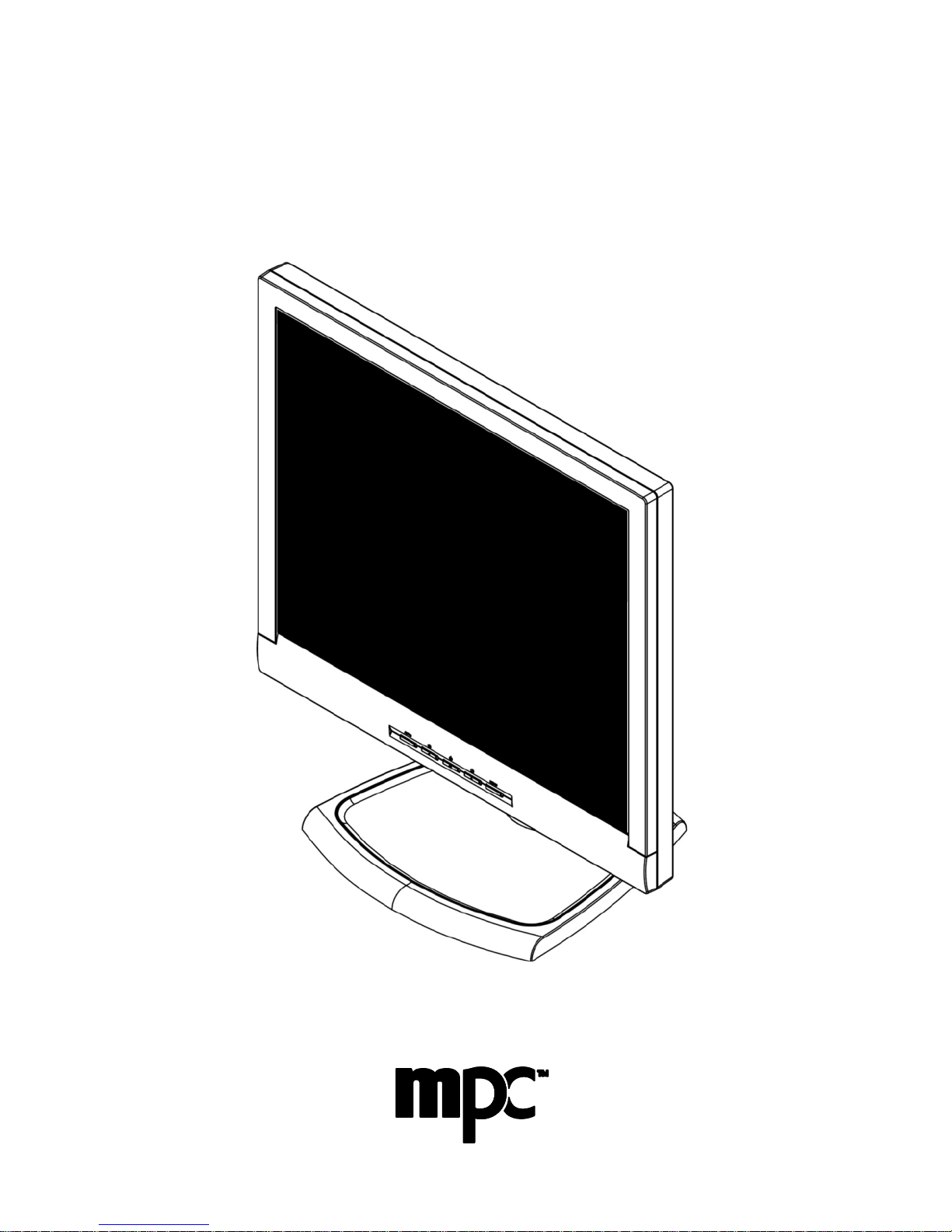
F1950i LCD
Monitor
User’s Guide
Page 2

MPC Computers 2005 © MAS001985-00
2
TABLE OF CONTENTS
Monitor User’s Guide ...................................................................3
Packing List....................................................................................3
Safety Information.........................................................................3
LCD Monitor Features and Cleaning..........................................5
Monitor Features ............................................................................. 5
Cleaning the Monitor ........................................................................ 5
Setup Instructions.........................................................................6
Monitor Base.................................................................................. 6
Power Cord ..................................................................................... 7
Video Cable.................................................................................... 8
Adjusting the Viewing Position....................................................8
Operating Instructions ...............................................................10
General Instructions ........................................................................10
Front Panel Controls .......................................................................10
Accessing the Adjustment Controls .................................................11
Adjusting the Picture ......................................................................12
Monitor Drivers...........................................................................15
Technical Support.......................................................................15
Features.......................................................................................16
Energy Star® Standards ..................................................................16
Plug and Play DDC1/2B Feature ......................................................16
Appendix A — Troubleshooting................................................17
Appendix B — VESA Mounting..................................................19
Attaching an Optional Wall-Mounting Arm.........................................19
Appendix C — On-Screen Messages.......................................20
Appendix D — Factory Preset Timing ......................................21
Appendix E — Connector Pins..................................................22
Appendix F — Acceptable LCD Defects...................................22
Appendix G — Monitor Specifications.....................................23
Appendix H — FCC Notice.........................................................25
Page 3

MPC Computers 2005 © MAS001985-00
3
MONITOR USER’S GUIDE
This user’s guide provides important information about operating your monitor.
Before using the monitor, please read this guide thoroughly, and save it for
future reference.
The information included in this publication is as accurate as possible based
on data received from manufacturer and other sources. Some information is
subject to change over time. MPC is not responsible for changes that may
occur with or without our knowledge.
PACKING LIST
Before setting up and using your monitor, examine the items in the monitor
package. If anything is missing or damaged, please contact MPC
immediately. Look for the following items:
• 19” LCD monitor
• F1950i LCD Monitor User’s Guide
• 100/120 VAC-rated power cord
• Monitor base
• DB-15 Analog and DVI-D Digital Video Signal Cables
Note: Save the original shipping carton and packing materials to transport
or ship your monitor. If you transport the monitor over long distances,
completely repackage the monitor in its original packing material.
SAFETY INFORMATION
• Do not use the monitor near standing bodies of water or in humid
envirionments.
• Set the monitor on a flat, stable surface. Do not place it on an unstable
cart, stand, or table. If the monitor falls, it might injure a person and/or
cause serious damage to the monitor.
• When placing the monitor on a cart or stand, use only a cart or stand
recommended by the manufacturer or sold with the monitor. If you mount
the monitor on a wall or shelf, use a mounting kit approved by the
manufacturer and follow the kit instructions.
• The monitor is equipped with a three-prong, grounded plug (a plug with a
third pin for grounding). For safety purposes, this plug will only fit into a
grounded power outlet. If your outlet does not accommodate the threeprong plug, have an electrician install the correct type of outlet, or use an
adapter to ground the appliance safely.
Page 4

MPC Computers 2005 © MAS001985-00
4
• The monitor must only be connected to the AC power source as indicated
on the label. If you are unsure of the type of AC power available, ask your
local power company. Only connect this monitor to a power outlet that
matches the power requirements of this monitor.
• Slots and openings in the back and bottom of the monitor are provided for
ventilation. To ensure reliable operation of the monitor and to protect it
from overheating, these openings must not be blocked or covered. Do not
place the monitor on a bed, sofa, rug, or similar surface. This monitor
must never be placed near or over a radiator or heat register. This monitor
must not be placed in a built-in enclosure of any kind unless proper
ventilation is provided.
• During a lightning storm, unplug the monitor. Also, unplug the monitor
when it will not be used for a long time. This will protect the monitor from
damage due to power surges.
• Do not overload power strips and extension cords. Overloading power
strips and extension cords can result in a fire or electric shock.
• Never push objects of any kind into the monitor through openings. The
objects could touch dangerous voltage points or short out parts, possibly
resulting in an electric shock or a fire hazard.
• Never spill liquid of any kind on the monitor. If this occurs, disconnect
from the power source immediately.
• Do not attempt to service the monitor yourself. Opening or removing the
monitor’s cover can expose you to dangerous voltages and other hazards.
Please refer all servicing to qualified service personnel.
• To ensure satisfactory operation, only use the monitor with UL listed
computers that have the appropriate configured receptacles marked
between 100–240 VAC, Min. 3.5A.
• Do not allow anything to rest on the power cord. Do not place the monitor
where people might walk on the cord.
• Do not place the monitor in direct sunlight or where it is near excessive
dust or mechanical vibration or shock.
Warning: To prevent a fire or shock hazard, do not expose the monitor
to rain or moisture. Dangerously high voltages are present inside the
monitor. Do not open the monitor cabinet. Refer servicing to qualified
personnel only.
Warning: Keep all packing materials away from children.
Page 5

MPC Computers 2005 © MAS001985-00
5
LCD MONITOR FEATURES AND CLEANING
Monitor Features
• 19-inch (483 mm) TFT color LCD monitor
• 100mm x 100mm VESA mounting pad
• EPA EnergyStar
®
Compliant
• Ergonomic design (complies with MPRII)
• Space-saving, compact case design
• Integrated power supply
• 3-point Display position adjustment (tilt, pivot and height)
The following occurrences are normal with an LCD monitor and do not indicate
a problem.
• Due to the nature of the internal fluorescent backlights, the screen may
flicker during initial use. If this occurs, turn off the monitor and then turn it
on again, making sure the flicker disappears.
• You may find slightly uneven brightness on the screen depending on the
desktop pattern you use.
• The LCD screen has an effective pixel count of 99.99% or more. It may
include blemishes of 0.01% or less, such as a missing pixel or a pixel lit
all of the time. Refer to Appendix F for additional details.
• Due to the nature of the LCD screen, an after-image or ghost of the
previous image may remain after switching the image when the same
image is displayed for a long time. In this case, you can recover the
screen slowly by changing the image or turning off the monitor for a few
hours.
• The life of the internal fluorescent backlights used in the LCD monitor is
approximately 30,000 hours. Contact MPC Technical Support or an
authorized dealer for a replacement when the screen is dark, flickering, or
not lighting up. Never attempt to replace the light yourself. Refer servicing
to qualified personnel only.
Cleaning the Monitor
To keep the monitor looking new, periodically clean the monitor’s case with a
soft cloth. As a safety precaution, always unplug the monitor before cleaning
it. Stubborn stains on the monitor’s case can be removed using a damp, dustfree cloth and a mild detergent solution. Never apply water directly to the LCD
screen. Always apply the water to the cloth first, and then wipe down the
screen. You can also purchase and use monitor wipes to clean the LCD
screen.
Caution: Never use strong solvents, such as thinner, benzene, or
abrasive cleaners because these will damage the monitor.
Page 6

MPC Computers 2005 © MAS001985-00
6
SETUP INSTRUCTIONS
The following sections provide information about attaching the base to your
monitor and using the power cord and video cables.
Caution: DO NOT remove the spring retention pin from pedestal until
base is installed and monitor is upright because this may damage the
monitor.
Monitor Base
INSTALLING BASE
To install the monitor base, place the base on a firm, flat surface and insert
the monitor pedestal into the base (2) until it snaps into place. After the
pedestal is firmly seated in the base, remove spring retention pin (1) to allow
height adjustments. DO NOT DISCARD the spring retention pin. It may be
needed for relocation or base removal.
Install Remove
Figure 1: Installing and Removing the Monitor Base
Page 7
MPC Computers 2005 © MAS001985-00
7
REMOVING BASE
Before attempting to remove the base, fully collapse the monitor and reinsert
the spring retention pin (1) in the pedestal. To remove the monitor base, gently
turn the monitor upside down and press the four retention clips together (3) to
release the base. Pull the base straight away from the monitor. (See Figure
1.)
Power Cord
Before connecting your monitor’s power cord, read the guidelines below:
• This monitor has an integrated universal power supply. It can operate in
either a 100/120 VAC or 220/240 VAC voltage area. (No user adjustment
is required.)
• Make sure the power cord meets the specifications and requirements for
your area. The power cord included with your monitor is rated for 100/120
VAC.
Caution: If the AC outlet is not grounded (with three holes), install the
proper grounding adapter (not supplied).
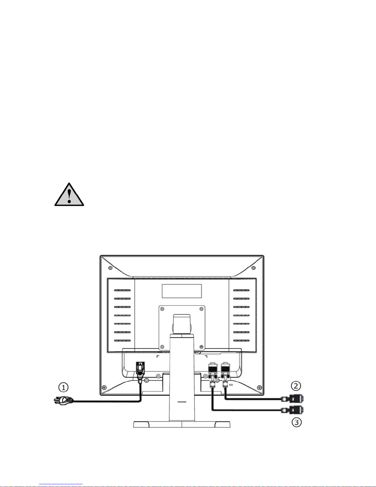
Plug the power cord (1) into the AC IN connection on the display and plug the
other end of the power cord into a three-pin AC power outlet or a UL-approved
power strip. (See Figure 2.)
Figure 2: Connecting Cables
Page 8
MPC Computers 2005 © MAS001985-00
8
Note: A certified power supply cord must be used with this equipment. The
relevant national installation and/or equipment regulations need to be
considered. Use a cord that meets the following criteria:
• Monitor side must have IEC320-type female, straight plug
• Main side must have IEC320-type male, straight plug
• Wire type must be UL/CSA certified, 18 AWG X 3C
Video Cable
The monitor comes with separate video cables for analog and digital
connections. The cable you choose to use will depend on the input type you
select. The analog cable has a blue 15 pin connector at each end. The digital
cable has a white 24+ pin connector at each end.
1 Plug the video cable connector into the computer's video port, taking care
not to bend any pins on the connector.
2 Plug the other end of the video cable into the appropriate Video (VGA or
DVI) connection on the monitor (See (2) and (3) in Figure 2.), taking care
not to bend any pins on the connector.
3 Tighten the two screws on each end of the video cable with your fingers to
secure the connection.
Caution: Over-tightening this connection can damage the monitor
cable or your computer’s video card.
ADJUSTING THE VIEWING POSITION
• For optimal viewing, look at the full face of the monitor, and then adjust
the monitor’s angle and height to your own preference.
• Hold the base so the monitor does not fall when you change the monitor’s
angle.
•
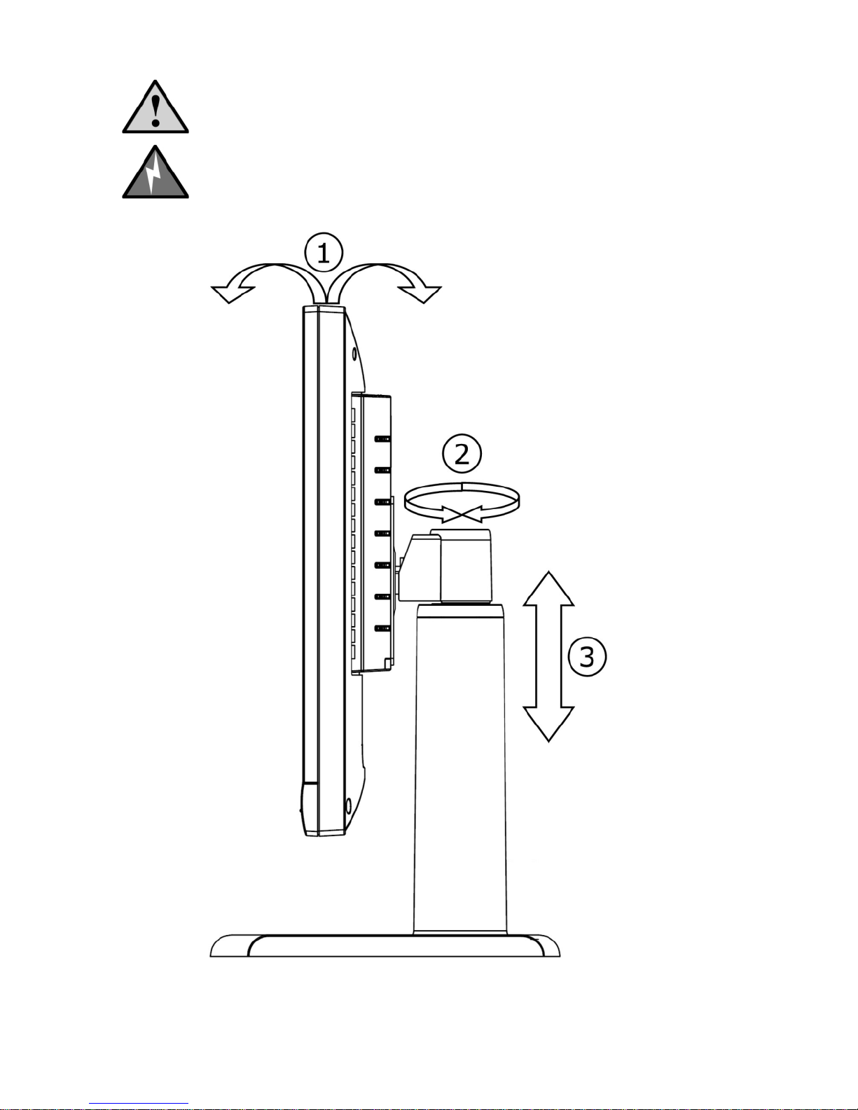
The monitor’s tilt angle may be adjusted from -2° to 25° (1).
•
The monitor’s left/right pivot position may be adjusted +/- 35° (2).
•
The monitor’s height may be adjusted up to 565mm (3).
Caution: To avoid breaking the wires inside the cable, do not bend the
signal cable excessively.
Page 9
MPC Computers 2005 © MAS001985-00
9
Figure 3: Adjusting the viewing position
Caution: Do not touch the LCD screen when you change the position,
or the screen may become damaged or broken.
Warning: Be careful not to pinch your fingers when adjusting the
monitor’s position.
Page 10
MPC Computers 2005 © MAS001985-00
10
OPERATING INSTRUCTIO NS
The following sections provide information about operating and adjusting your
monitor.
General Instructions
To turn on the monitor, do the following:
1 Check that the power cord is connected to the monitor and a power outlet
or socket.
2 Check that the video cable is connected securely to the monitor and to
your computer’s video port.
3 Locate and press the power button. The power indicator will light up. The
monitor features a unique quick-switch system. A picture should appear
within seconds after the monitor is turned on. (See Figure 4 and Table 1.)
Front Panel Controls
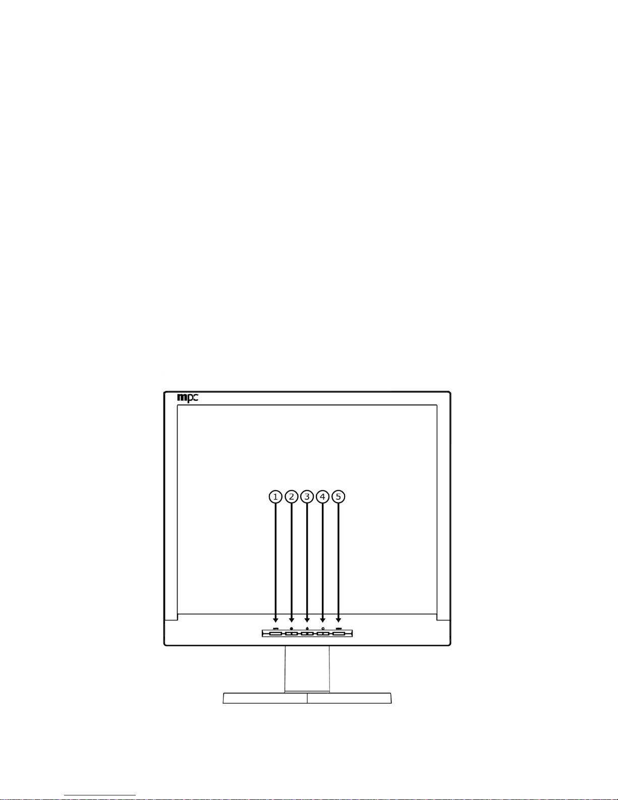
The Power button is located on the front panel of the monitor. The buttons to
the left and right of the Power button are for adjusting the monitor’s picture.
See Figure 4 and Table 1 for the layout and names of the control buttons.
Figure 4: Control Buttons
Page 11
MPC Computers 2005 © MAS001985-00
11
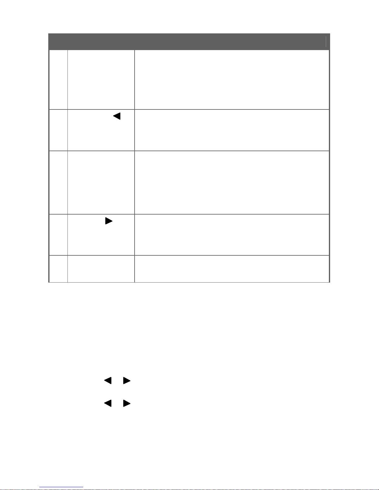
Table 1: Control Buttons Descriptions
Feature Description
1 Auto Config/Exit
The Auto Config button is used to automatically set the HPos, V -Pos, Clock, and Focus. Press and hold this button
for two seconds to begin the auto config cycle. This also
acts as the Exit button. Press it to close the On Screen
Display (OSD) menu. This will also back out of a menu
selection. Auto Configuration is disabled for Digital input.
2
Brightness /
Press this button to adjust the display brightness. If the
OSD is open, this button will move through the selections
in the OSD. After a selection is made in the OSD, this
button will decrease the value of the selection.
3 Power Button /
Power LED
Press this button to turn the monitor on and off.
The Power LED is integrated into the power button.
LED Indication:
Green = power on mode (normal operation)
Orange = low power mode (low power consumption; no
picture)
4
Contrast /
Press this button to adjust the display contrast. If the OSD
is open, this button will move through the selections in
the OSD. After a selection is made in the OSD, this button
will increase the value of the selection.
5 Menu/Enter
Press this button to open the OSD menu or to select an
adjustment icon within the OSD.
Accessing the Adjustment Controls
The following list explains how to access and use the adjustment controls
appearing in the On Screen Display (OSD) Main Menu. The OSD has two
levels of selection. Level 1 is for functions and Level 2 is for adjustments.
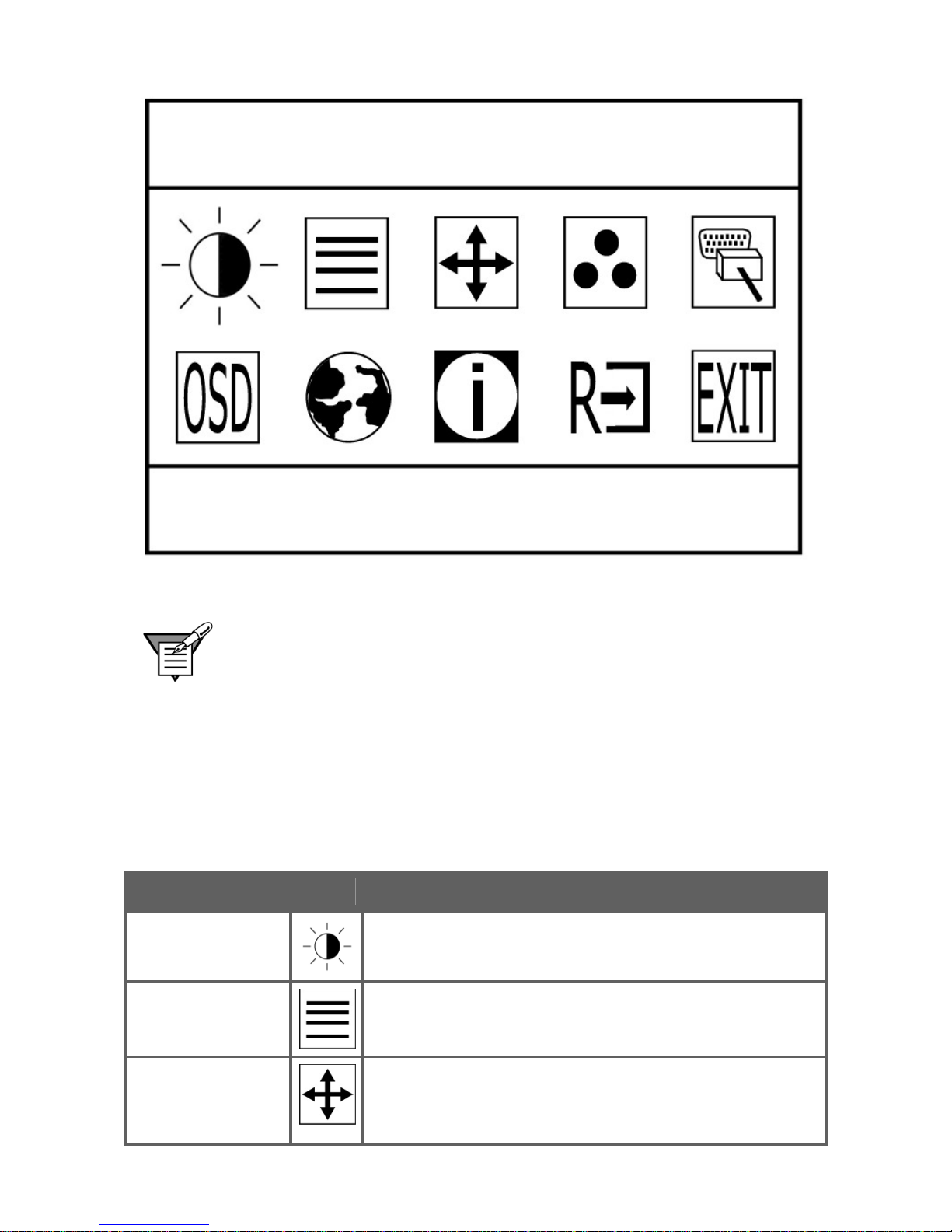
1 Press the Menu button to make the Level 1 OSD window appear. The
menu will look like Figure 5.
2 Press the or buttons to locate the desired function.
3 Press the Menu button to select the function that you want to access.
4 Press the or buttons to change the value of the current adjustment.
• To exit and save, select the Exit function, or leave the monitor alone
until the OSD disappears. If you want to adjust any other function,
repeat steps 2-4.
Page 12
MPC Computers 2005 © MAS001985-00
12
Figure 5: On Screen Display (OSD) Menu
Note: If you do not make any OSD menu adjustments or selections
during
the OSD timeout period, the current setup will be saved, and the OSD will
disappear automatically.
Selecting a Control
The table below describes the functional control icons that appear on the Level
1 OSD menu.
Table 2: Functional Control Icons
Function Icon Description
Luminance
Use this to enter the Luminance control. Contrast
and Brightness are adjustable in this section.
Image Setup
Use this to enter the Image Setup control. Focus
and Clock are adjustable in this section.
Image Position
Use this to enter the Image Position control.
Horizontal and Vertical Position are adjustable in
this section.
Page 13
MPC Computers 2005 © MAS001985-00
13
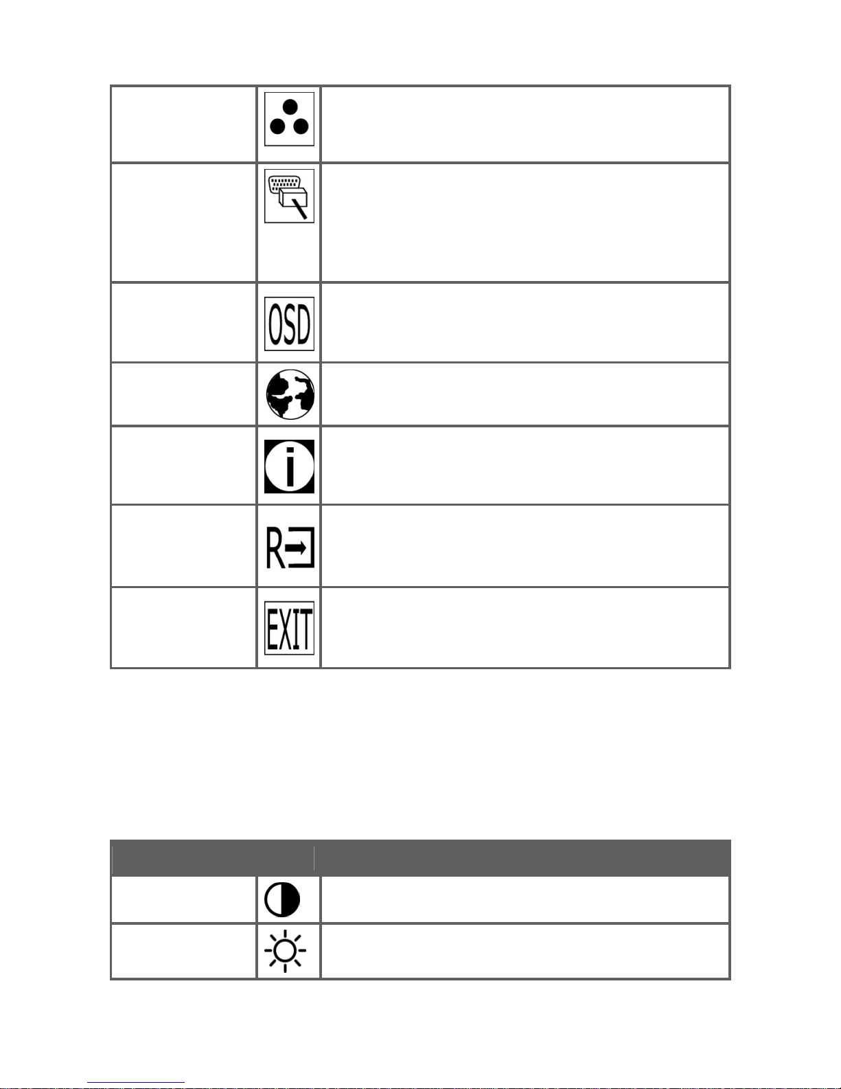
Table 3: Functional Control Icons (Continued)
Color Temp.
Use this to enter the Color Temperature control.
Two presets are selectable as well as the user
adjustable color levels.
Input Select
Use this function to select analog or digital input.
When Digital is selected the following controls will
be disabled: Clock, Phase, H-Position and VPosition. These adjustments are not necessary
with a digital source.
OSD
Use this to enter the OSD Control. OSD position and
timeout is adjustable here.
Language
Use this function to select which language the
monitor will use to display the instructions.
Information
Use this function to view the current display
resolution and frequency.
Reset
Use this function to clear each old status of autoconfiguration and to redo auto-configuration.
Exit
Use this feature to save your selections and
adjustments and to exit the OSD menu.
Adjusting the Picture
The table below describes the adjustment control icons that appear on the
Level 2 OSD menu.
Table 3: Adjustment Control Icons
Adjustment Icon Description
Contrast
Use this function to adjust the picture’s contrast.
Brightness
Use this function to adjust the picture’s brightness.
Page 14
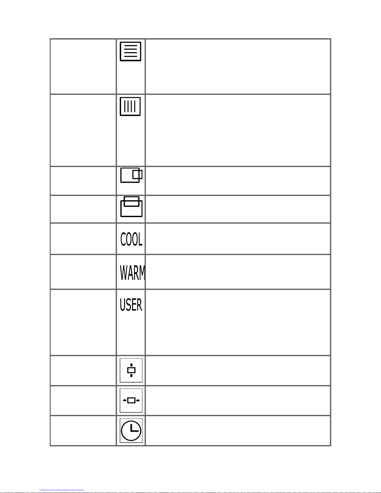
MPC Computers 2005 © MAS001985-00
14
Table 3: Adjustment Control Icons (Continued)
Focus
Use this function to adjust the picture’s focus.
Focus adjusts the phase of the pixel clock signal.
With a wrong phase adjustment, the picture has
horizontal disturbances or lines in a bright picture.
Disabled when using Digital input.
Clock
Use this function to adjust the picture’s clock.
Clock (pixel frequency) controls the number of
pixels scanned by one horizontal sweep. If the
frequency is not correct, the screen shows vertical
stripes and the picture will not be the correct width.
Disabled when using Digital input.
H-Position
Use this function to adjust the picture’s horizontal
position. Disabled when using Digital input.
V-Position
Use this function to adjust the picture’s vertical
position. Disabled when using Digital input.
Color Adjustment
Cool Preset
Use this option to set the color to a cool white
setting that is better for viewing text. This setting
has less RED than the WARM setting.
Color Adjustment
Warm Preset
Use this option to set the color to a warm white
setting. This setting has more RED than the COOL
setting and is better for viewing pictures.
Color Adjustment
User Adjustable
Blue - Use this function to adjust the picture’s blue
intensity.
Green - Use this function to adjust the picture’s
green intensity.
Red - Use this function to adjust the picture’s red
intensity.
OSD Vertical
Position
Use this function to adjust the OSD’s vertical
position.
OSD Horizontal
Position
Use this function to adjust the OSD’s horizontal
position.
OSD Time Out
Set the time the OSD stays on screen with no
interaction. The range is from 10 to 120 seconds.
Page 15

MPC Computers 2005 © MAS001985-00
15
MONITOR DRIVERS
During normal operation, your system will automatically detect your monitor,
and Plug and Play drivers will automatically be installed.
If your application requires a specific monitor driver and color matching profile,
these can be downloaded from the MPC Technical Support Site at
http://support.mpccorp.com.
If you do not have Internet access, you may also call MPC Technical Support
at (800) 877-8856 to request that the files be sent to you.
TECHNICAL SUPPORT
In the unlikely event that you have a failure with your MPC monitor, you can
contact MPC Technical Support at http://support.mpccorp.com.
If you do not have Internet access, you may also call MPC Technical Support
at (800) 877-8856.
Technical Support will provide you with instructions for returning the failed
monitor.
For warranty information, refer to the MPC Legal Web site at:
http://www.mpccorp.com/about/legal/legal.html.
Page 16

MPC Computers 2005 © MAS001985-00
16
FEATURES
Energy Star® Standards
This monitor may appear to be non-functional if there is no video input signal.
For this monitor to operate properly, there must be a video input signal.
This monitor meets power management standards as set by the Video
Electronics Standards Association (VESA) and/or the United States
Environmental Protection Agency (EPA) and the Swedish Confederation
Employees (NUTEK). This feature is designed to conserve electrical energy
by reducing power consumption when there is no video input signal present.
When there is no video input signal, this monitor, following a time-out period,
will automatically switch to a low power consumption mode. This reduces the
monitor's internal power supply consumption. After the video input signal is
restored, full power is restored, and the display is automatically redrawn. The
appearance is similar to a "Screen Saver" feature, except the display is
completely off. The display is restored by pressing any key on the keyboard
or clicking the mouse.
Plug and Play DDC1/2B Feature
This monitor is equipped with VESA DDC1/2B capabilities according to the
VESA DDC STANDARD. These capabilities allow the monitor to inform the
host system of its identity and, depending on the level of DDC used,
communicate additional information about its display capabilities. The
communication channel is defined in two levels: DDC1 and DDC2B.
The DDC1 is a uni-directional data channel from the display to the host that
continuously transmits EDID information. The DDC2B is a bi-directional data
channel based on the I²C protocol. The host can request EDID information
over the DDC2B channel.
For more information, see Appendix E — Connector Pins .
Page 17
MPC Computers 2005 © MAS001985-00
17
APPENDIX A — TROUBLESHOOTING
If the following information does not successfully solve your issue, please visit
the MPC Technical Support Site at http://support.mpccorp.com.
If you do not have Internet access, you may also call MPC Technical Support
at (800) 877-8856.
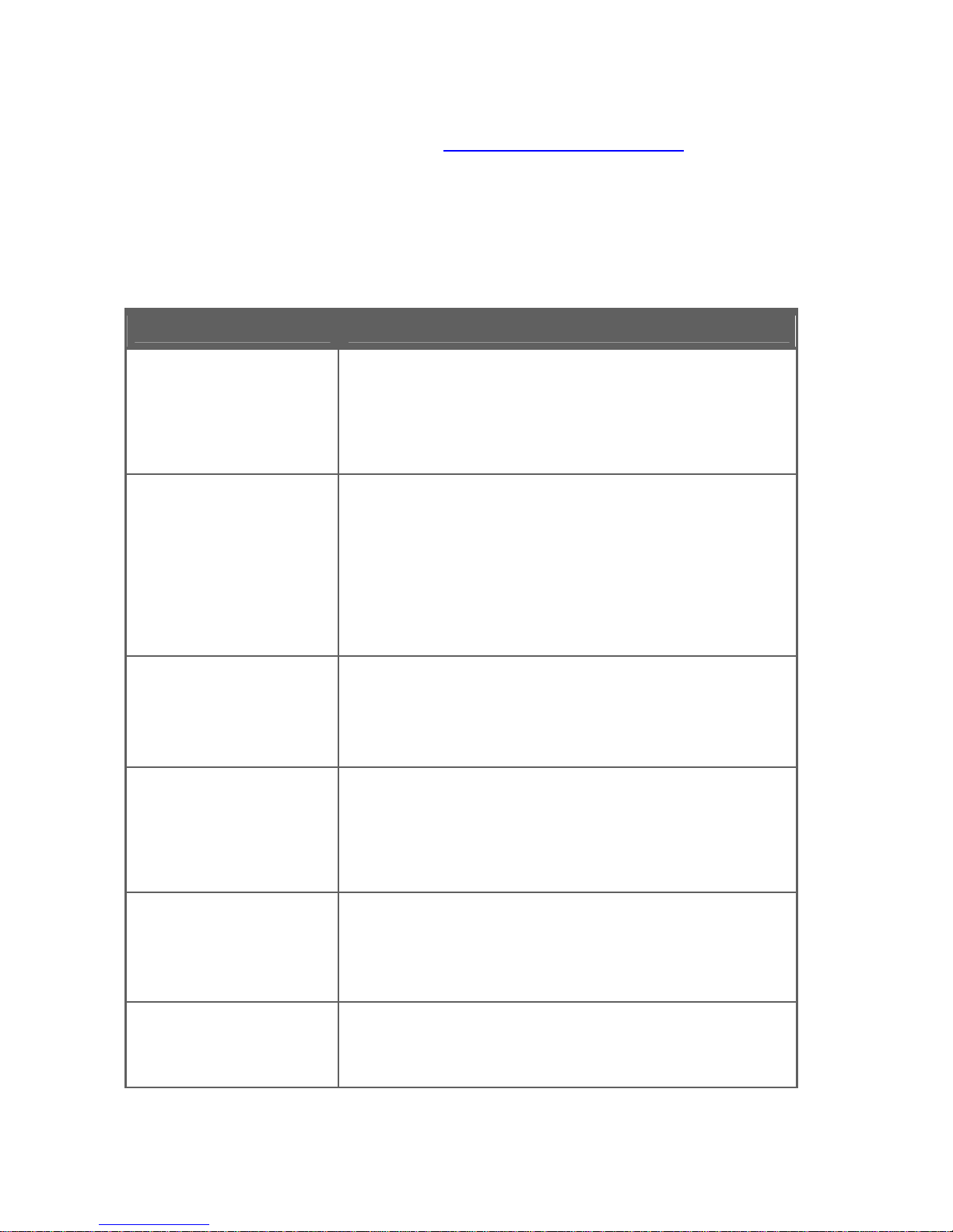
Table 4: Troubleshooting Monitor Issues
Issue Solution
The power indicator
LED is not lit.
• Press the monitor Power button once to see if
the LED comes on.
• Verify that the power cord is plugged in firmly
and correctly.
The monitor is not
detected by the
system when it is
connected.
• Verify the PC system is Plug and Play
compatible.
• Verify the video card is Plug and Play
compatible.
• Check the DB -15 plug on the video cable for
bent pins.
The picture is fuzzy.
• Adjust the Contrast and Brightness controls.
• Initiate the automatic calibration function by
pressing the Auto button.
The picture bounces
or a wave pattern is
present in the picture.
• Initiate the automatic calibrat ion function by
pressing the Auto button.
• Manually adjust the Clock and Focus controls
for better picture.
The monitor’s picture
is missing one of the
primary colors (red,
green, or blue).
• Inspect the monitor’s video cable and make
sure that none of the pins are bent.
The picture has color
defects (white does
not look white).
• Adjust the RGB color or select a color
temperature.
Page 18
MPC Computers 2005 © MAS001985-00
18
Table 4: Troubleshooting Monitor Issues (Continued)
Issue Solution
The power LED is on
(orange), but there is
no video or picture.
• Make sure the monitor’s video cable is
properly connected to the computer.
• Inspect the monitor’s video cable and make
sure that none of the pins are bent.
• Make sure that the computer is operational by
pressing [Caps Lock] on the keyboard while
observing the Caps Lock LED. The LED
should turn either on or off after you press
[Caps Lock].
• Your computer may be in a low power state.
Move the system’s mouse and press several
keys on the keyboard to wake the system.
• Make sure the computer’s video card is
completely seated in the slot.
The screen image is
not centered or sized
properly.
• Adjust pixel frequency (Clock) and Focus, or
press the Auto Config button.
• Select the Auto Center function in the OSD
to center the display.
The picture has poor
brightness or contrast.
• The lifetime of the backlight is limited. After
20,000 to 30,000 hours of use, the luminance
of the light may be reduced to half of its
original value. Please send the monitor to an
authorized service agent.
There are horizontal or
vertical disturbances
on the screen.
• Use a repetitive dot pattern to manually adjust
the Clock and Focus, or press the Auto
Config button.
Page 19
MPC Computers 2005 © MAS001985-00
19
APPENDIX B — VESA MOUNTING
Attaching an Optional Wall-Mounting Arm
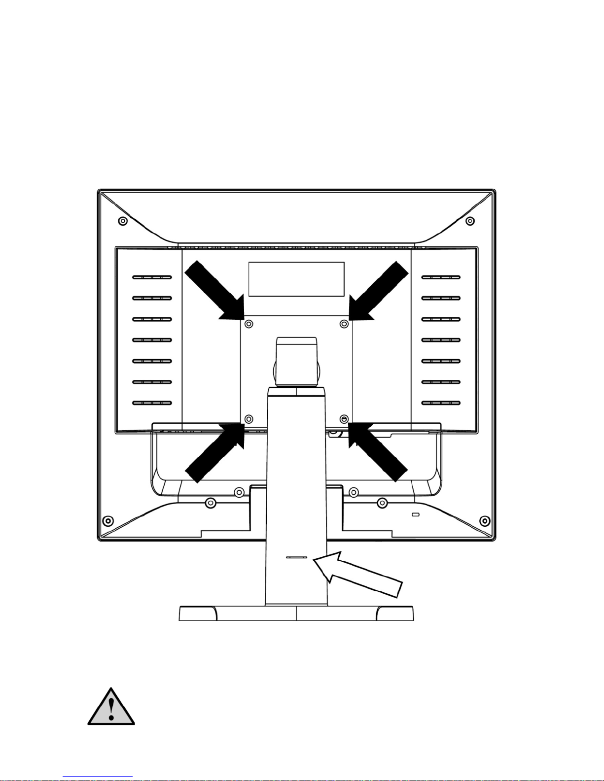
This monitor can be attached to a wall-mounting arm, which you purchase
separately. This monitor has a 100 mm x 100 mm VESA compliant mounting
pad. Use a wall-mounting arm with a VESA compatible configuration only.
Figure 6: Installation of an Optional Wall-Mounting Arm
Caution: Be careful when installing the wall-mounting arm. To avoid
LCD damage, make sure you properly support the monitor.
Page 20
MPC Computers 2005 © MAS001985-00
20
Preparing to Install a Wall-Mounting Arm
To prepare to install a wall-mounting arm, complete the following steps:
1 If the monitor is currently in use, turn it off and disconnect the power cord
and video cable.
2 Lower the display and re-insert the spring retention pin. (See white arrow
in Figure 6.)
3 Pull the screw cover off the back of the monitor if it is in place.
4 Carefully place monitor face down on a flat padded surface.
5 Support the base and remove the screws. (See black arrows in Figure 6.)
6 Remove the base and pedestal.
7 Follow the manufacturer's instructions to assemble the wall-mounting
arm.
Installing a Wall-Mounting Arm
To install the wall-mounting arm, complete the following steps:
1 Place the wall-mounting arm or mounting plate onto the back of the
monitor. Line up the holes of the arm or plate with the holes in the back of
the monitor.
2 Insert the four screws int o the holes and tighten. (See black arrows in
Figure 6.) Be careful not to overtighten the screws.
3 Attach arm to mounting plate, if required.
4 Insert the power cable into the slot on the back of the monitor and
reconnect the video cable.
APPENDIX C — ON-SCREEN MESSAGES
Table 5: On-Screen Messages
Message Action
No Signal
• Check that the signal cable is properly
connected. If the connector is loose, tighten
the connector screws.
• Check the DB -15 plug on the video cable for
bent pins or other damage.
Input Not Supported
• Your system may be set outside the display
mode range of the monitor. Verify you are
using a compatible display mode. (See Table
6: Factory Preset Timing.)
Page 21
MPC Computers 2005 © MAS001985-00
21
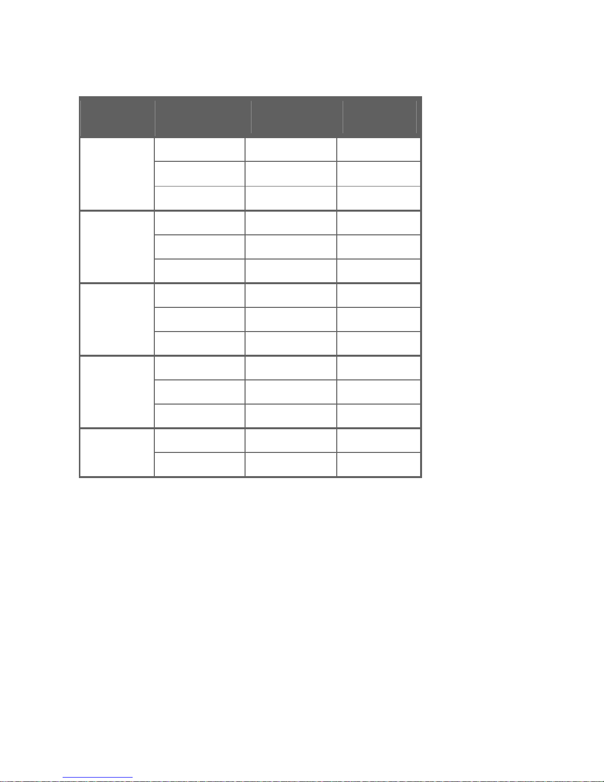
APPENDIX D — FACTORY PRESET TIMING
Table 6: Factory Preset Timing
Standard Resolution Horizontal
Frequency
Vertical
Frequency
640 x 350 31.469 kHz 70 Hz
640 x 400 31.469 kHz 70 Hz
DOS
720 x 400 31.469 kHz 70 Hz
640 x 480 31.470 kHz 60 Hz
640 x 480 37.861 kHz 72 Hz
VGA
640 x 480 37.500 kHz 75 Hz
800 x 600 37.879 kHz 60 Hz
800 x 600 48.077 kHz 72 Hz
SVGA
800 x 600 46.875 kHz 75 Hz
1024 x 768 48.363 kHz 60 Hz
1024 x 768 56.476 kHz 70 Hz
XGA
1024 x 768 60.023 kHz 75 Hz
1280 x 1024 63.981 kHz 60 Hz
SXGA
1280 x 1024 79.976 kHz 75 Hz
Page 22
MPC Computers 2005 © MAS001985-00
22
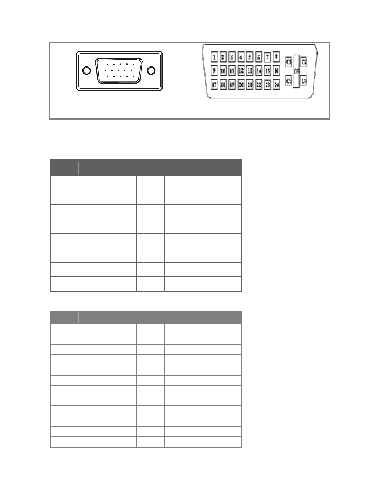
APPENDIX E — CONNECTOR PINS
1 5
6
10
11 15
DB-15 Analog Connector DVI Digital Connector
Figure 7: Signal Cable Connectors
Table 7: DB-15 Analog Video Cable Pin Assignments
Pin # Description Pin # Description
1 Red 9 +5V
2 Green 10 Detect Cable
3 Blue 11 NC
4 Ground 12 DDC-Serial Data
5 Ground 13 H-sync
6 R-Ground 14 V-sync
7 G-Ground 15 DDC-Serial Clock
8 B-Ground
Table 8: DVI Digital Video Cable Pin Assignments
Pin # Description Pin # Description
1 TMDS RX2 - 13 Floating
2 TMDS RX2+ 14 +5V Power
3 TMDS Ground 15 Ground
4 Floating 16 Hot Plug Detect
5 Floating 17 TMDS RX0 6 DDC Clock 18 TMDS RX0+
7 DDC Data 19 TMDS Ground
8 Floating 20 Floating
9 TMDS RX1 - 21 Floating
10 TMDS RX1+ 22 TMDS Ground
11 TMDS Ground 23 TMDS Clock+
12 Floating 24 TMDS Clock-
Page 23
MPC Computers 2005 © MAS001985-00
23
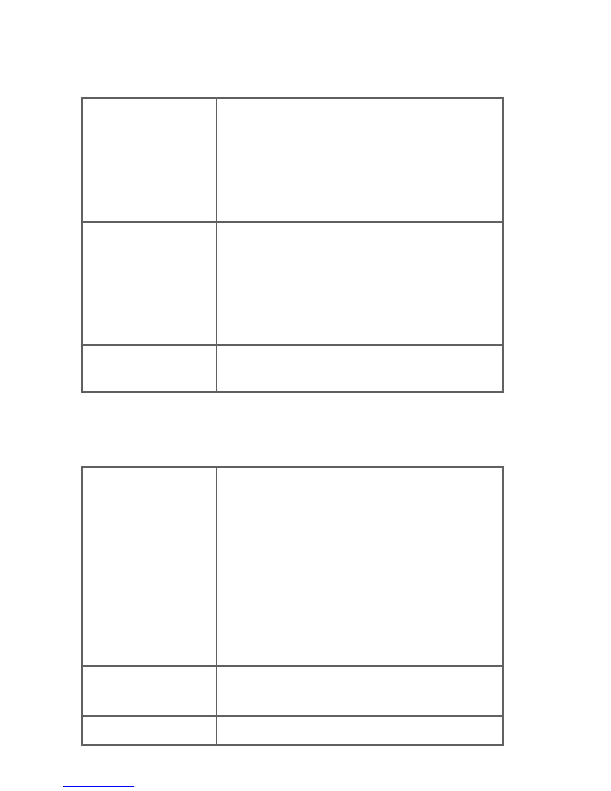
APPENDIX F — ACCEPTABLE LCD DEFECTS
Table 9: Acceptable LCD Panel Defects
Bright Dot Failures
(Always On)
Bright dots are tested
with full screen black
pattern (R,G,B=0,0,0)
• Maximum five red, green, or blue bright dots
(sub-pixels)
• Maximum three green dots
• Maximum one joined bright dot
• Minimum distance between two bright dots:
10 mm
Black Dot Failures
(Always Off)
Black dots are tested
with full screen white
pattern
(R,G,B=255,255,255)
• Maximum five black dots
• Maximum two joined (adjacent) black dots
• Minimum distance between two black dots:
10mm
• No defects allowed with three adjacent black
dots
Total Dot Failures
• Maximum of eight dots (including bright and
dark dot defects)
APPENDIX G — MONITOR SPECIFICATIONS
Table 10: Monitor Specifications
LCD Panel
• Type: TFT Active Matrix Color LCD
• Size: 19.0 in (48.3 cm)
• Viewable size: 19.0 in (48.3 cm)
• Pixel pitch: 0.294 mm (H) x 0.294 mm (V)
• Viewing angles: 170°(H) 170°(V) (Typical)
• Response time: 20 ms (Typical)
• Native panel resolution: 1280 x 1024
• Contrast ratio: 800:1 (Typical)
• Brightness: 250 nits (Typical)
Scan Range
• H-Frequency: 30 kHz to 83 kHz
• V-Frequency: 55 Hz to 75 Hz
Dot Clock
• 165 MHz
Page 24
MPC Computers 2005 © MAS001985-00
24
Table 10: Monitor Specifications (Continued)
Recommended
Viewing Resolutions
• Minimum: 640 x 480 @ 60 Hz
• Nominal: 1280 x 1024 @ 60 Hz
• Maximum: 1280 x 1024 @ 75 Hz
Maximum Resolution
• 1280 x 1024
Display Colors
• 8bit True Color - 16.7 million colors native
Plug and Play
• VESA DDC1/2B
TM
EPA ENERGY STAR®
• On Mode: <60 W
• Active Off Mode: <3 W
Input Connectors
• 15-pin D-Sub (Analog)
• 24+ pin DVI (Digital)
Input Video Signal
Analog and Digital
• 0.7 Vp-p (standard)
• 75 OHM
• Positive
Power Source –
Integrated Power
Supply
• AC Source: 100 to 240 VAC 50/60 Hz
Environmental
Considerations
• Operating Temp: 41°F to 95°F
(5°C to 35°C)
• Storage Temp: -4°F to 140°F
(-20°C to 60°C)
• Operating Humidity: 10% to 85%
Weight
• Shipping: 19.8 lb (9.0 kg)
• Display Only: 15.5 lb (7.02 kg)
• Display without base: 11.2 lb (5.08 kg)
Dimensions
• 422(W) x 457(H) x 248(D) mm
Regulatory
Compliance
• UL, CSA, FCC, GS/TUV, CE
NOTE: The specifications listed here are subject to change without notice.
Page 25

MPC Computers 2005 © MAS001985-00
25
APPENDIX H — FCC NOTICE
FCC Class B Radio Frequency Interference Statement
This device complies with Part 15 of the FCC rules. Operation is subject to
the following two conditions: 1) this device may not cause harmful
interference, and 2) this device must accept that any interference received,
including interference that may cause undesired operation. If this equipment
does cause harmful interference to radio or television reception (which can be
determined by turning the equipment off and on), the user is encouraged to try
to correct the interference by one or more of the following methods:
1 Reorient or relocate the receiving antenna.
2 Increase the separation between the equipment and the receiver.
3 Plug the equipment into an outlet on a different circuit than the receiver.
4 Consult the dealer or an experienced radio/TV technician for help.
Notice:
Any changes or modifications to the monitor not expressly approved by the
party responsible for compliance could void the user's authority to operate the
equipment.
Shielded interface cables and AC power cord, if any, must be used to comply
with the emission limits.
The manufacturer is not responsible for any radio or TV interference caused by
unauthorized modification to this equipment. It is the responsibility of the user
to correct such interference.
This product meets the ENERGY STAR guidelines for energy efficiency.
 Loading...