

Page 1

MPB S.r.l.
Via Giacomo Peroni 400/402
00131 Rome - Italy
Tel +39 0641200744
Fax +39 0641200653
[email protected]
www.gruppompb.com
User’s manual
SEMS & SEMS LIGHT
Shielding Effectiveness Measurement
System
Updated to the software Version:
SEMS RX 1.32
SEMS TX 1.05
SEMS PC Utility 1.26
MPB 2014 ver. 2_9
Page 2

USER’S MANUAL
S E M S
SAFETY NOTE
Read before using the product
MPB works to provide to its customers the best safety conditions available
complying with the current safety standards.
The instrumentation described in this manual has been produced, tested and left the
factory in conditions that fully comply the European standards.
To maintain it in safe conditions and ensure the correct use, these general
instructions must be fully understood and applied before using the product.
The SEMS is designed for industrial environment and laboratories and should be
used by skilled staff only.
MPB disclaims responsibility for a different use of the device.
- 2 -
Page 3
USER’S MANUAL
S E M S
Conformity Certificate
This is to certify that the product: SEMS / SEMS LIGHT
(Measurement system of shielding effectiveness)
complies with the following European Standards:
This product complies with the requirements of the Low Voltage Directive
2006/95/CE, and with the EMC Directive 2004/108/CE.
(in accordance with the ISO/IEC 17050-1)
Safety: CEI EN 61010-1 (2002)
EMC: EN 61326-1 (2007)
MPB S.r.l.
- 3 -
Page 4
1. Gener
al information
2. Operating principle
3. System use and operation
4.
SEMS PC Utility
software, controls and
Index
USER’S MANUAL
S E M S
1.1. Introduction
1.2. System description
1.3. Composition of the system and optional accessories
1.4. Receiver front panel
1.5. Transmitter front panel
1.6. Receiver/transmitter rear panel
1.7. Technical specifications
Pag.
5
5
6
8
8
9
10
- 4 -
2.1. SEMS receiver
2.2. SEMS transmitter
2.3. SEMS system
2.4. Power saving and recalibration
3.1. Turn on menu
3.2. Std Menu
3.2.1. Cal Menu
3.2.2. High Dynamic (HiDyn)
3.2.3. Show Menu
3.2.4. Meas Menu
3.2.5. Menu Sniff
3.3. WIZ Menu
3.3.1 Measurements using wizard
3.4. STP Menu
3.5. Measuring the shielding attenuation
3.6. Calibration using CalKit
3.7. Measurement with Rod antennas mod. R1
3.8. Unconnected mode
3.9. Prequiet mode
3.10.SEMS Light
functions
4.1. Installation
4.2. Connecting the instrument
4.3. Retrieving a measurement
4.4. Program a frequencies List with Scan or
table List
4.5. Working with the results
4.6. Firmware upgrade
11
11
12
12
13
13
14
16
20
21
23
24
27
31
33
34
36
37
44
46
48
49
50
54
57
58
Page 5
3
USER’S MANUAL
S E M S
1. General information
1.1. Introduction
SEMS is thought to comply the raising need to test and verify the shielding
effectiveness of shielded environment in hospitals and industries.
This system allows to measure automatically with high speed and accuracy the
attenuation value of the magnetic and electric field in shielded environments.
1.2. System description
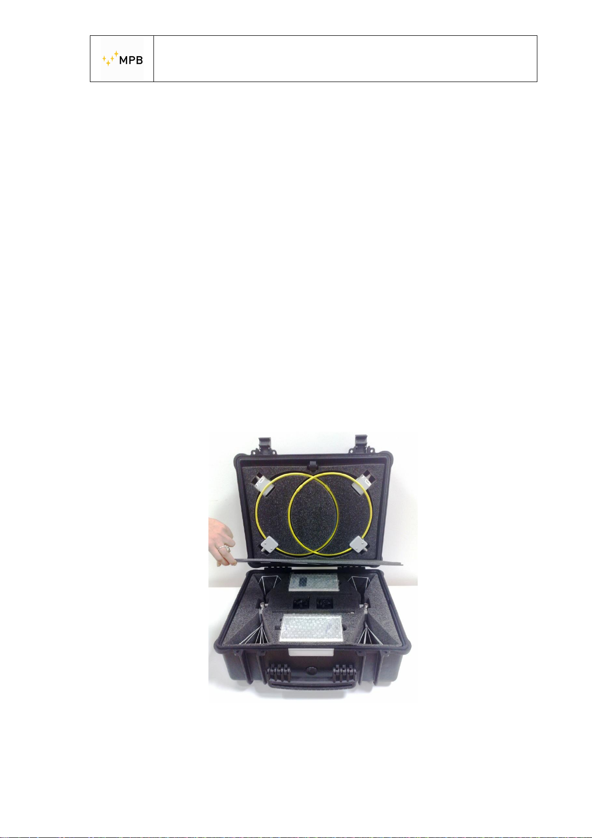
The shielding effectiveness measurement system has a transmitter and a receiver,
both of them are provided with a pair of very small antennas, to measure the
magnetic and electric field attenuation.
Contrary to today’s available systems, that measure the shielding effectiveness on
few frequency points, SEMS allows to perform a complete test on the whole
frequency ranges continuously. Another improvement compared to the standard
system is the synchronization component, TX and RX are connected by a wireless
system that allows to perform automatically the measurement m inimizing the user’s
errors.
Picture n°01
SEMS System
- 5 -
Page 6
SEMS KIT 1
SEMS LIGHT
3
USER’S MANUAL
S E M S
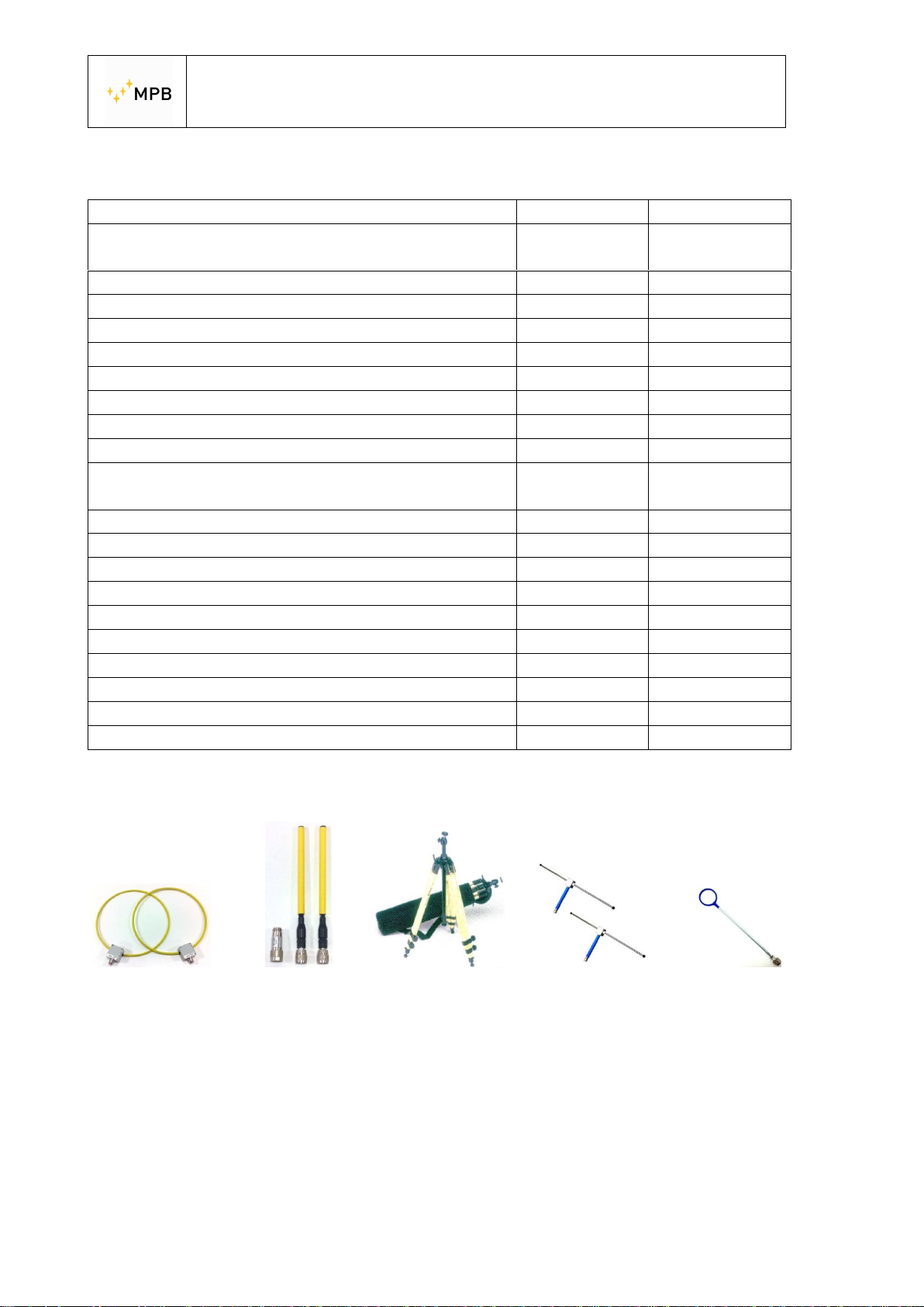
1.3. Composition of the system and optional accessories
Model
RX Unit (10kHz…300MHz)
TX Unit (10kHz…300MHz)
Biconical antennas Mod. B1 (60…300MHz)
Rod antennas Mod. R1 (1…60MHz)
Loop antennas Mod. L1 (2…128MHz)
Loop antennas Mod. L2 (10kHz…4MHz)
Loop antennas Mod. L3 for RF Leak
Dipole antennas Mod. D1 (40…300MHz)
RS/232 Wireless Key Bluetooth technology
RS232/USB cable to download memory of the
ü
ü ü
ü ¡
¡ ¡
ü ü
¡ ¡
¡ ¡
¡ ¡
ü ü
ü ü
SEMS and for programming
Battery Charges
Carrying bag Mod. SEMS-CC
Antenna adapters N(m)-N(m)
Cal-Kit 4 attenuators 30 dB/each
Cal-Kit Accredia Certificate
Woden tripode Mod. TR-02 Hight adjustable
Optical link Mod. LO with 20m fiber
Software Mod. SEMS-SW
User’s manual onto USB key
Standard Calibration Certificate SEMS-STD
ü ü
ü ü
ü ü
¡ ¡
¡ ¡
¡ ¡
¡ ¡
ü ü
ü ü
ü ü
Option ¡
Only until
96MHz
Loop Mod. L-2 Rod Mod.R1 Tripode Mod.TR-02-A Dipole Mod. D-1 Loop Leak Mod. L-3
- 6 -
Picture n°02
Page 7
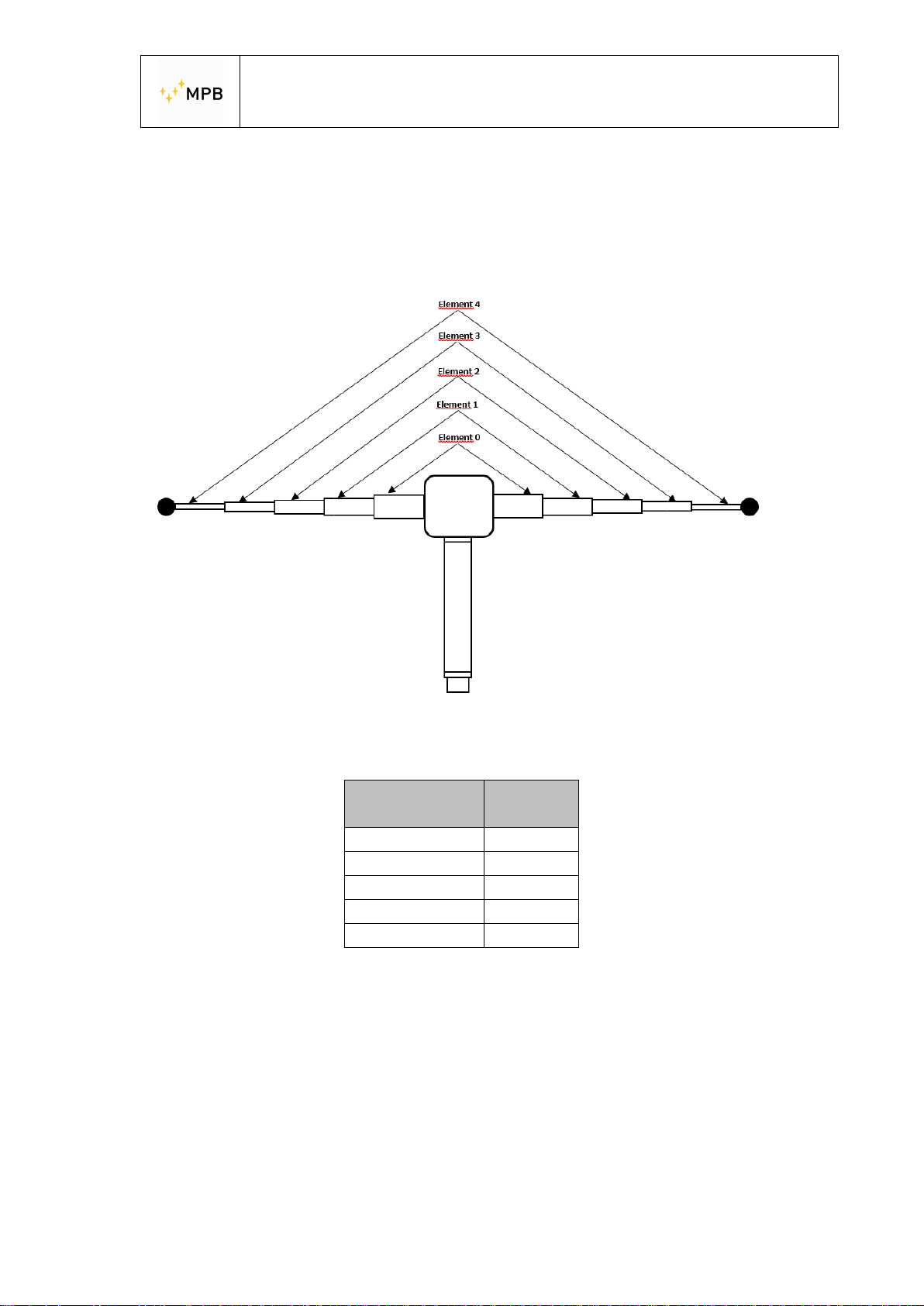
DYNAMIC
WITH DIPOLE ANTENNA MODEL D1
TIPS TO HAVE THE BEST
USER’S MANUAL
Frequency range
[MHz]
200-300 0
140-240 0+1
90-180 0+1+2
70-140 0+1+2+3
40-120 0+1+2+3+4
S E M S
Extended
element
- 7 -
Page 8
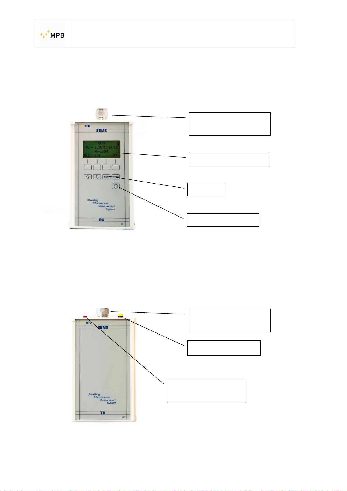
Alphanumeric display
RF in 50 Ohm
RF out 50 Ohm
LED on when
USER’S MANUAL
S E M S
1.4. Receiver front panel
In the Picture below(n°03) is represented SEMS receiver front panel. It has a
display and a command keyboard.
N female connector
Keyboard
Power button
Picture n°03
1.5. Transmitter front panel
The SEMS transmitter (Picture n° 04) has no command button but only a power
button and a led to indicate that the transmission is active, since the commands are
sent by the receiver using the wireless connection.
N female connector
Power button
Picture n°04
- 8 -
transmission is active
Page 9
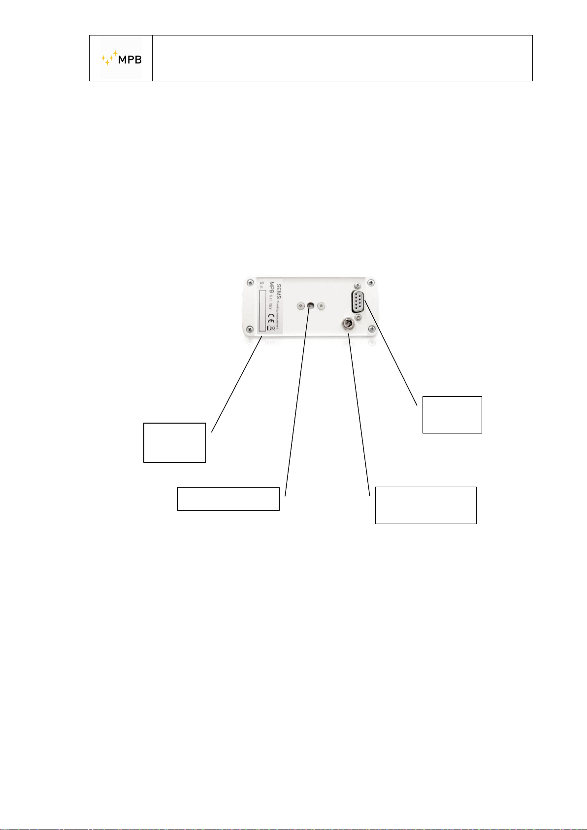
Serial
Thread insert ¼
Batte
ry charger
USER’S MANUAL
S E M S
1.6. Receiver / Transmitter rear panel
The rear panels (Picture n° 05) are the same for both devices and upon them is
possible to find the serial number, the thread used for the tripod, the battery charger
connector and the RS232 interface for the wireless link.
Picture n°05
RS232
number
connector
Important note: Always use the battery charger provided with the instrument to
avoid serious damages to the devices and operator’s injuries.
Important note: The battery charger must be connected to both devices (Tx and
Rx) turned off.
- 9 -
Page 10

Antennas
Weight and dimensions
USER’S MANUAL
S E M S
1.7. Technical specifications
Frequency range for TX/RX
Resolution
RF out (TX module)
Max output power (typical)
RF in (RX module)
VSWR
Attenuator
Max input power
Dynamic Range
IF bandwidth (RX module)3 dB bandwidth
Attenuation measurement accuracy
(typical)
I/O interface
Buzzer
International standard compliance
Operating temperature
Battery
Loop Mod.L-1
Loop Mod.L-2
Rood Mod. R-1
Dipole Mod. D-1
Loop Mod. L-3
Biconical Mod. B1
Accessories
Wooden Tripode Mod. TR-02-A
Optical Link Mod. LO
Calibration Set-Up and Measurement
Overall weight
Case dimensions
Technical specifications may change without notice
10 kHz…300 MHz (SEMS Light up to 96 MHz)
10 Hz
Z
50 Ω, N fem.
out
+30 dBm
Zin 50 Ω, N fem.
< 1.2
0…20dB
110 dBuV
120 dB
5/150Hz
10 kHz…30 MHz ± 1.0 dB
30 MHz…300 MHz ± 1,5 dB
RS232 / Wireless
To set on attenuation level
MIL-Std-285 IEEE Std 299 EN 50147-1
NSA65-6
0°….40°C
Irreplaceable and rechargeable Li-Ion
(6 h operating time)
Frequency range 2…128 MHz
Diameter 30 cm
Frequency range 10 kHz…4 MHz
Diameter 30 cm
Frequency range 1…60 MHz
Adjustables on lenght
Frequency range 40…300 MHz
Adjustable on extension
Used for RF Leak
Frequency range 60…300 MHz
Width 35 cm
Adjustable in high
With 20 m. fiber
Programmable with the software
9,4 kg
52x43x23cm
- 10 -
Page 11
USER’S MANUAL
S E M S
2. Operating principle
2.1. SEMS Receiver
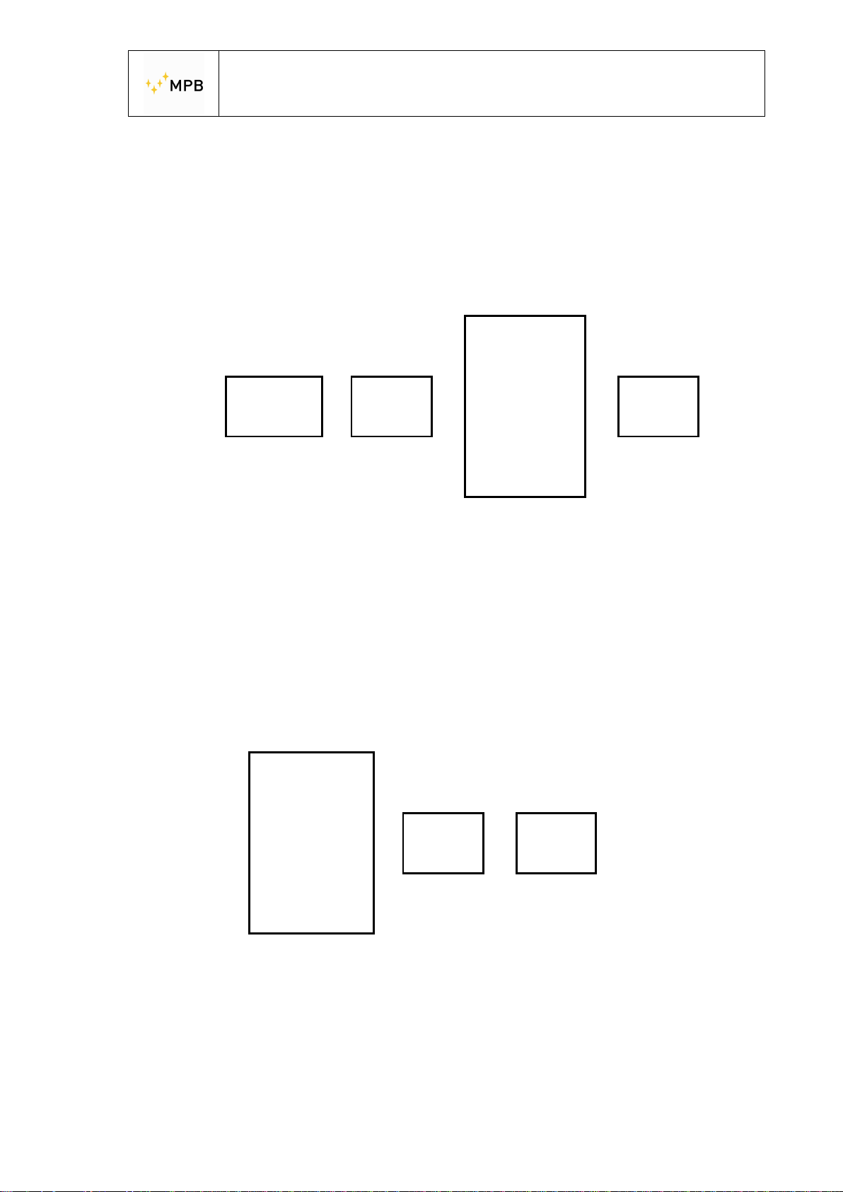
The block diagram (a) below represents the SEMS receiver.
Digital
RF
IN
Attenuator
> Filters > > Display
ADC
RSP
DSP
Figure a)
First of all the RF signal received by the antenna is attenuated by the attenuator
module to fit the level to the next modules specifications, subsequently we can find
the filters to select the bandwidth depending on the frequency settings. Then the RF
signal is converted by an ADC and is processed by the digital part with a RSP and a
DSP, the result will be shown on the display.
2.2. SEMS Transmitter
The block diagram below (b) represents the SEMS transmitter.
Digital
CPU
DDS
> Doubler >
Power
amplifier
RF
OUT
Figure b)
The transmitting signal is generated using the DDS controlled by the CPU that
receives the instructions from the receiver wireless interface, this signal is
duplicated and amplified in order to achieve the necessary level to be transmitted by
the transmitting antenna.
- 11 -
Page 12
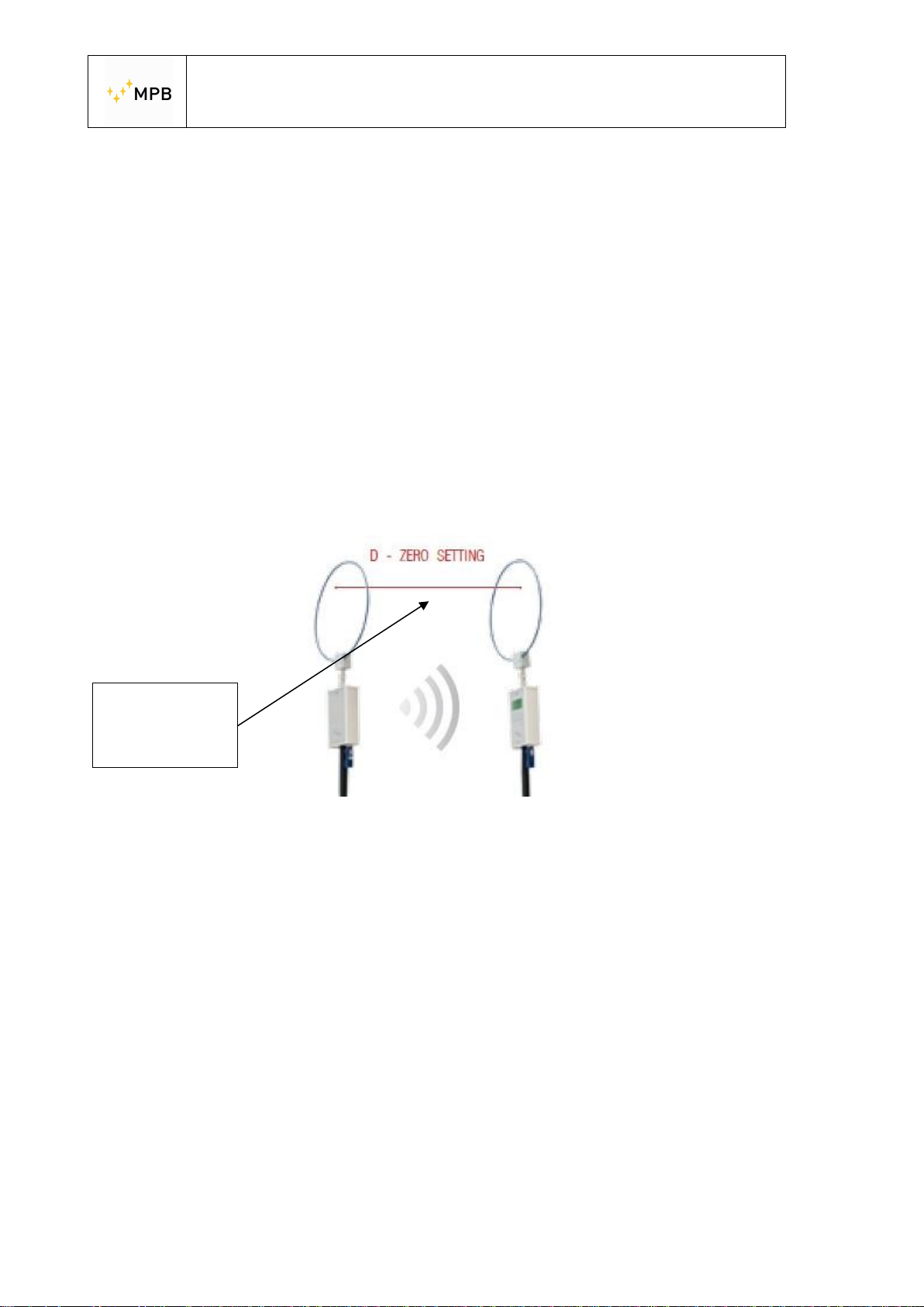
Distance for
USER’S MANUAL
S E M S
2.3. SEMS System
The main purpose of the SEMS is to measure the shielding effectiveness in a
shielded environment by measuring the attenuation of the electric or magnetic field.
The SEMS makes an a relative measure and not absolute
We can briefly describe the operating principle as it follows:
The transmitter generates a RF signal and irradiates it through the antenna, at a
certain distance the receiver catches the signal with an equal antenna and
measures the signal level. If we move the receiver inside the shielded environment
maintaining the same distance from the transmitter we will get a lower signal, so we
can consider the shielding attenuation the difference between the reduced and the
original signal.
the zeroing
process
Picture n°06
Example of zeroing with loop antennas
2.4. Power saving and recalibration
The SEMS has an integrated timer in both RX and TX unit for two different reasons:
the TX automatically turns off after 17 min of idle to save the battery; the RX unit
after 15 min from the last zero setting suggests to recalibrate the SEMS by
repeating the procedure.
- 12 -
Page 13
USER’S MANUAL
S E M S
3. System use and operations
3.1. Turn on menu
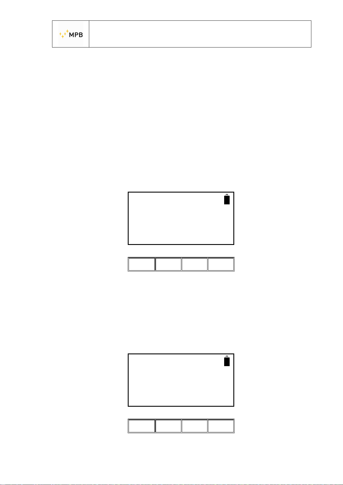
By pressing the power button of the RX module the device will turn on, to turn it off
press the power button for at least 4 seconds. Follow the same procedure for the TX
module.
As soon as the device is turned on, the display will show the following screenshot.
On the top right of the screen will appear a battery icon to show the charge status of
the RX module, then the TX connection on the top left will appear the TX device
battery icon.
“If the battery icon do not appear on the top left, there isn’t communication from the
units. Please check the configuration of the wireless Bluetooth” (Ind 3.5-page 32)
SEMS
FW – 1.32 27/03/14
HW-2
WIZ Std Stp
Ll ll Il ll
NOTE: As soon as the connection is established, if the red led of the wireless
devices blinks together with the yellow ones, wait until the complete switching off of
the first ones in order to let the devices synchronize and ensure the correct
functioning.
3.2. Std Menu
By pressing the Std menu button this screenshot will appear
SEMS
FW – 1.32 27/03/14
Show Cal
Ll ll ll ll
Then pressing the relative button allows the access to Show and Cal menu.
- 13 -
Page 14
USER’S MANUAL
S E M S
3.2.1. Cal Menu
Cal menu is used to perform the system zeroing process(Scan or List) or the system
calibration process(CalK)
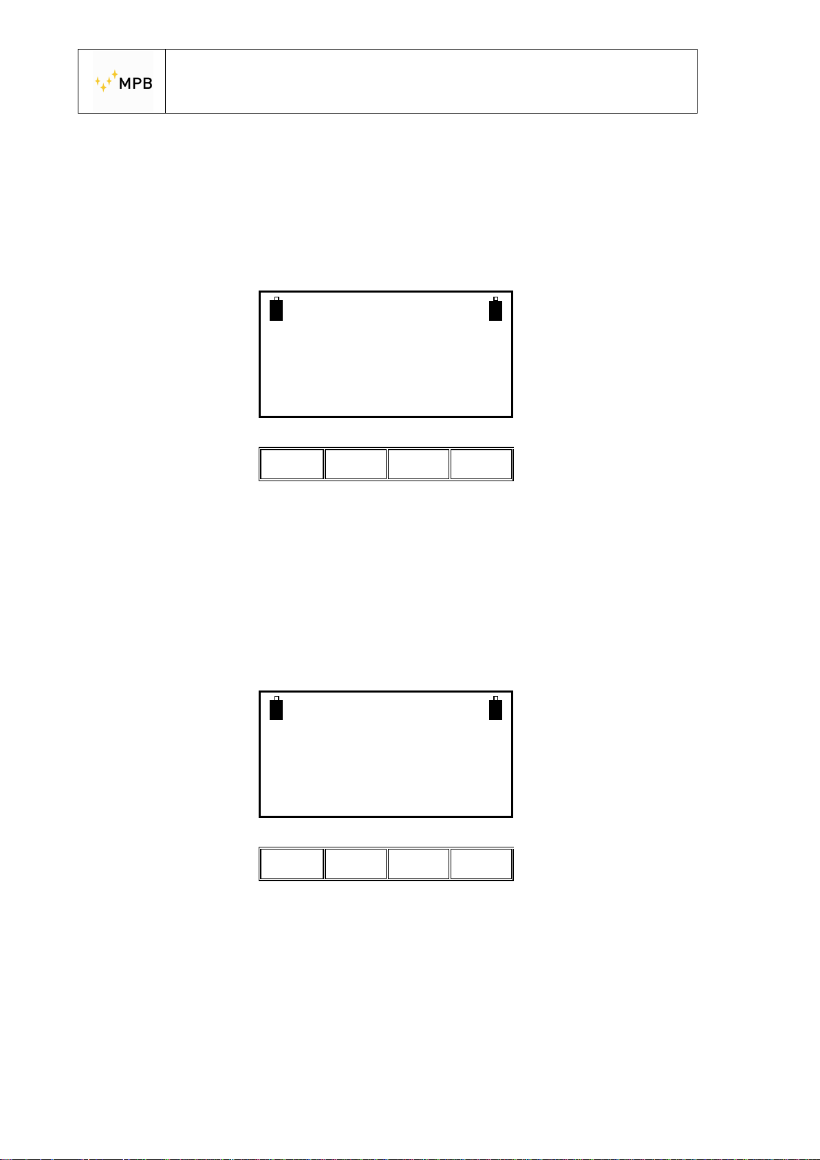
SEMS
Ready for Measuring
Scan List CalK
ll ll ll ll
Scan performs the system zeroing process using the standard or customized
frequency bands, by pressing the scan button we will see the following screenshot
where is possible to choose the default bands (L_Lo, L_Hi e Bic) or the user’s
customized bands (Sc1,Sc2,Sc3 and Sc4)pressing the User button (customized
bands are programmed with the “SEMS PC_Utility” software)
SEMS
Ready for Measuring
L_Lo L_Hi Bic User
ll ll ll ll
The choice of the button to press depends on the different types of antennas:
L_Lo (Loop antennas Mod. L2)
L_Hi ( Loop antennas Mod. L1)
Bic (Biconical antennas Mod. B1)
By pressing the User button will appear the screenshot to choose the memorized
band:
- 14 -
Page 15
USER’S MANUAL
S E M S
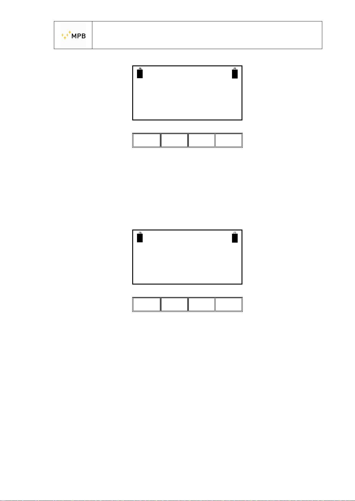
List performs the system zeroing process using the default or programmable
frequency list, by pressing the list button will appear a new menu where you can
select the default frequency list DFT or three programmable lists (L1, L2 e L3)
SEMS
Ready for Measuring
Sc1 Sc2 Sc3 Sc4
ll ll ll ll
SEMS
Ready for Measuring
CalK performs the system calibration process using the four 30 dB attenuators
(optional accessories CAL-KIT).
NOTE: This procedure needs a wireless connection between TX and RX, you can
control the connection with the battery status on the left top of the screen of RX (will
be visible only if the connection has been successful).
Note: Never use the CalKit procedure with the charger connected
When the zeroing procedure ends the following menu will appear:
DFT L1 L2 L3
ll ll ll ll
- 15 -
Page 16
BEEP
Clear
USER’S MANUAL
S E M S
3.2.2. HiDyn is a special function available only for a number max of 30 frequencies
With this mode the operator, during the zero step, is be able to understand if there is
some noise (radio frequency disturbance) at the same frequencies of the test, that
could compromise the dynamic of the measure
It’s possible make a scanning in automatic or manual mode just press the Stp menu
like show below:
And after the Beep button
SEMS
FW – 1.32 27/03/14
HW-2
ll ll ll ll
BEEP ON 100dB
Use arrows for
10 dB step
+1 -1 ON OFF
ll ll ll ll
BEEP ON/OFF enables or disables the manual or automatic execution of the HiDyn
Function
With the arrows is possible to set the threshold of the dynamics during the test
- 16 -
Page 17
USER’S MANUAL
S E M S
If f or example,before zero procedure we set this value at 100 dB ( with Beep “ON”)
the operator will know immediately if this threshold of dynamic will be available for
the measure
@ 9,900001 MHz
Dynamic :85 dB
** Above Minimum **
Abort
OK
ll ll ll ll
In this example the operator will know immediately how much dynamic will be
available during the measure at the frequency of 9,900001 MHz.
Confirming with “OK” the SEMS Receiver will proceed at the next frequency through
the activation of the “Best Dynamic” function like below:
For every frequency present in the table two additional side frequencies are added:
the lower is f*0.99 (-1%) and the higher is f*1.01 (+1%)
All the frequencies are then tuned on RX unit, while the TX unit is kept OFF, and for
each the noise floor is recorded.
At the end of this step, for each triplet the frequency point which shows lower noise
floor is taken while the remaining two are discarded. In this way now a new table,
same in number of point as the original one, is created.
- 17 -
Page 18
USER’S MANUAL
S E M S
You can at anytime stop the “Best Dynamic” function
Pressing the “Abort” button will show the menu below
Sems UnZeroed
Calibration Aborted
** Above Minimum **
Show Cal
ll ll ll ll
Anyway, you can view all the values of dynamic available for each frequency point
with the command “Show”, before to start the measuring:
Sems
Ready for Measuring
Meas Show Cal Snif
And after “Dyn”
ll ll ll ll
Sems
Ready for Measuring
** Above Minimum **
Dyn L1-4 M1-4 H1-4
ll ll ll ll
- 18 -
Page 19
USER’S MANUAL
S E M S
To view them one by one press the button NxFr ( Next frequency) or HiPk ( highest
Peak) and NxPk ( next Peak than the one displayed)
Dynamic
9.900 to 126.000
1stF NxFr HiPk NxPk
ll ll ll ll
- 19 -
Page 20
USER’S MANUAL
S E M S
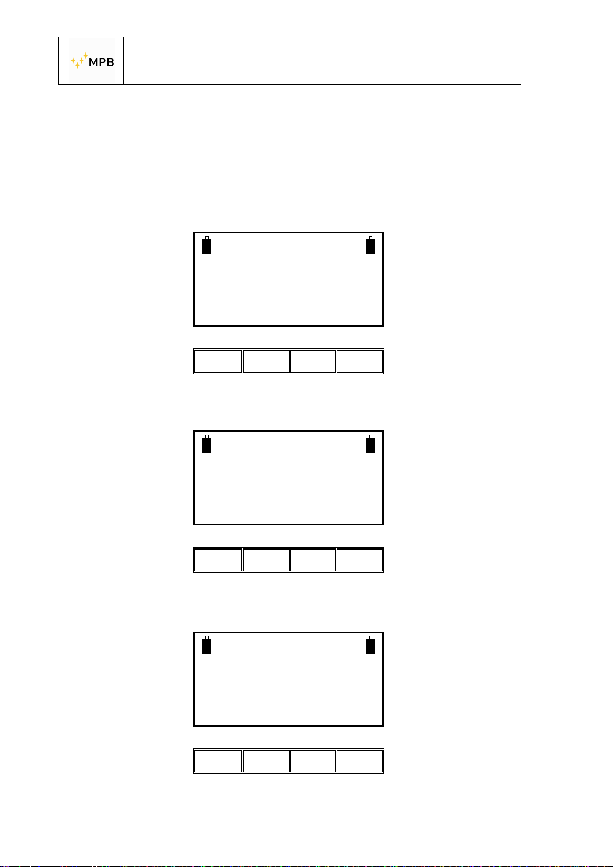
3.2.3. Show menu
The show menu will provide the results of the measurements performed and
previously stored
To see the saved measurements press the Show button
e.g. We will choose a measure stored in a memory named H1-4
SEMS
Ready for Measuring
Meas Show Cal Snif
ll ll ll ll
SEMS
Ready for Measuring
Last L1-4 M1-4 H1-4
ll Il ll ll
Then we recall the H1 memory
SEMS
Ready for Measuring
H-1 H-2 H-3 H-4
ll ll ll ll
- 20 -
Page 21
USER’S MANUAL
S E M S
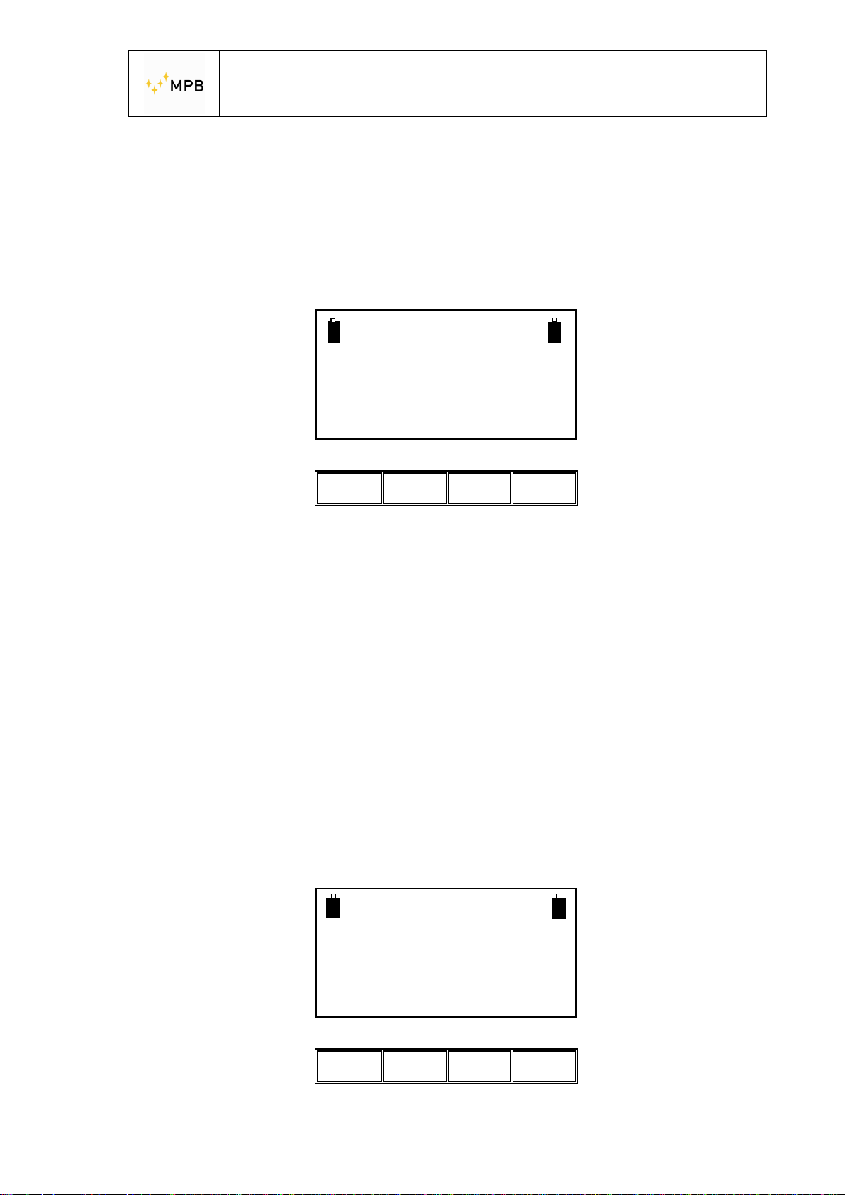
1stF Shows the attenuation at the lower frequency of the selected scan or list
NxFr Shows the attenuation on the next frequency
HiPk Shows the minimum attenuation on the whole scan or list
NxPk Shows the first relative minimum of attenuation from the current frequency
By pressing the Last button you will see the results of the last m easurement
performed, by pressing the remaining three buttons you can see the other stored
data. (up to 4 for each button).
As soon as you choose the measure to see you can analyze frequency by
frequency the measured attenuation.(The frequencies are always expressed in
MHz)
Scan
60.000 to 300.000
1stF NxFr HiPk NxPk
ll ll ll ll
By pressing the ESC button you can go back to the previous menu.
3.2.4. Meas menu
You can find the Meas command in the Std menu, but it will appear only when the
system is zeroed using the Cal command described in the previous paragraph
(3.2.1. of this manual).
SEMS
Ready for Measuring
Meas Show Cal Snif
ll ll ll ll
- 21 -
Page 22
USER’S MANUAL
S E M S
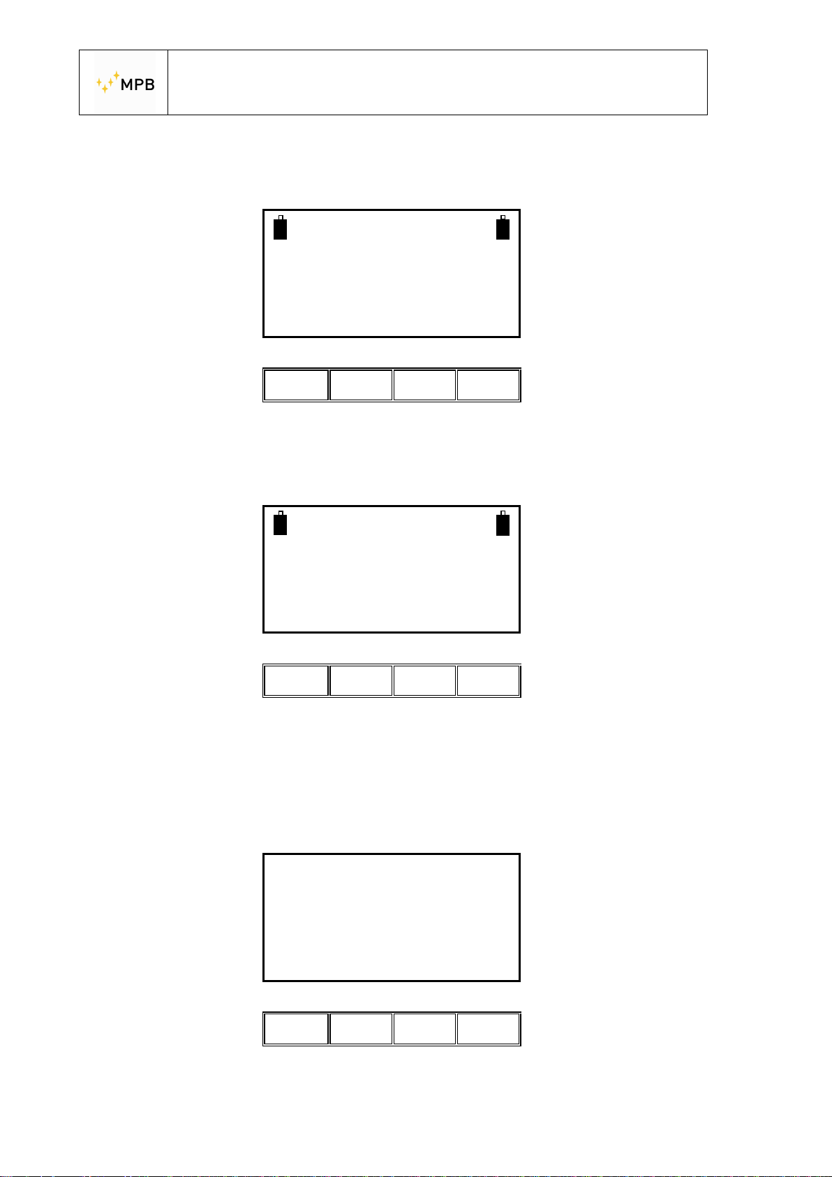
The command will perform a measurement of attenuation automatically (Auto), or
manually (Man).
Fully Zeroed
Ready for Measuring
Auto Man PreQ Unc
ll ll ll ll
Using the automatic mode you can choose if you want the measurement procedure
to start immediately (Now), or with a fixed time delay (10s, 30s, e 60s).
SEMS
Ready for Measuring
Now 10s 30s 60s
ll ll ll ll
If you use a manual measurement you will use the commands: (Prev) measure of
the previous frequency, (Next) measure of the next frequency, (Redo) in order to
measure the current frequency and (Abort) to end the measurement.To measure
the electrical component we recommend to use Rod Antennas ,Mod. R-1,
completely open or the Biconical antennas Mod. B-1 on RX and TX unit. For the
magnetic field you can use the pairs of Loop Antennas L-1 or L-2.
60.000000 MHz
Rbw:40 Hz.
Att: 56 dB
Prev Next Redo Abort
ll ll ll ll
- 22 -
Page 23
USER’S MANUAL
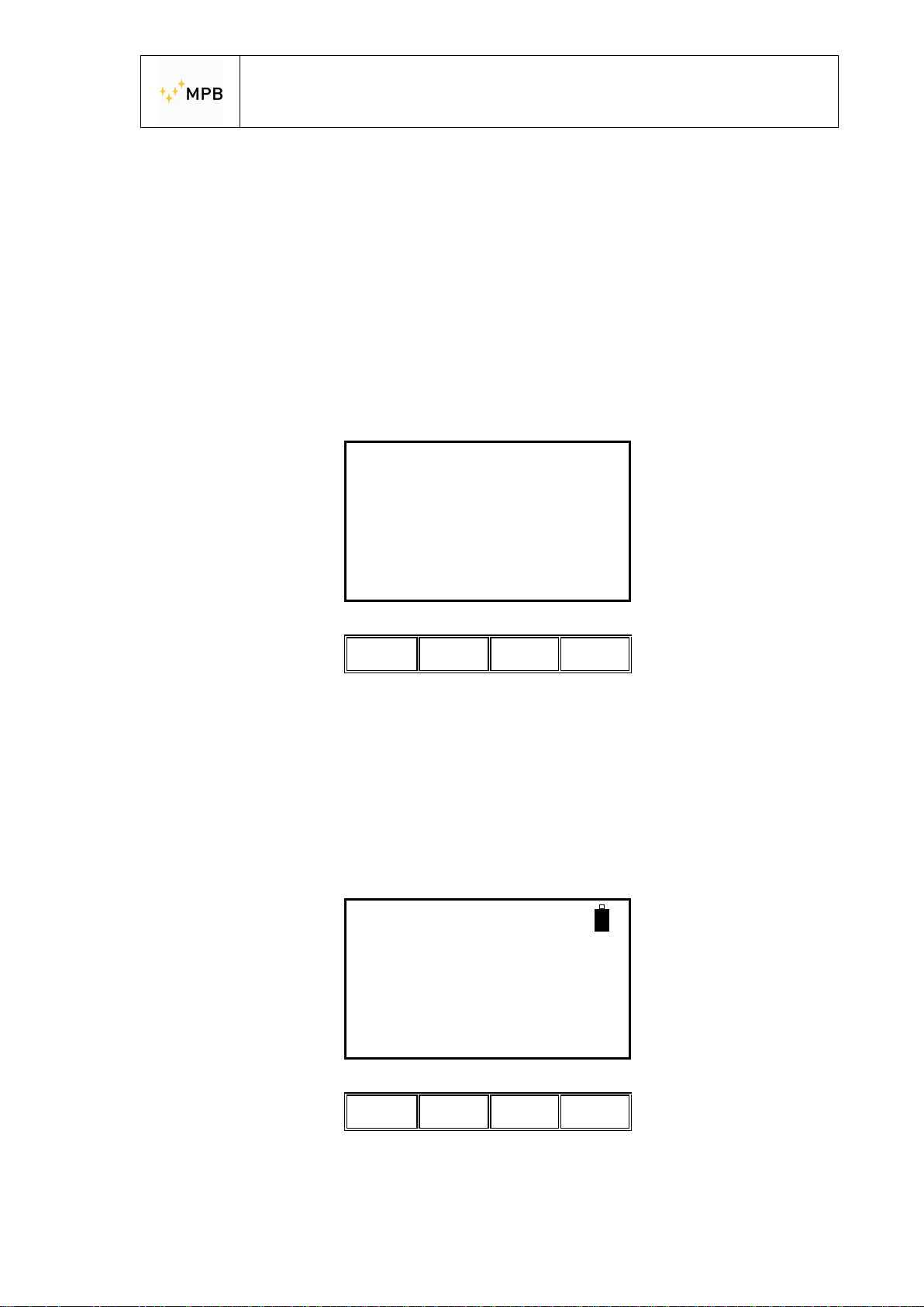
S E M S
When the measurement is finished the display will show the memory slot to store
the acquired data, you can choose one of the 4 memories for each frequency range:
Frequency Range from 0.01 to 2 MHz = memory (L-1, L-2, L-3 e L-4)
Frequency Range from 2 to 60 MHz = memory (M-1, M-2, M-3 e M-4)
Frequency Range from 60 to 300 MHz = memory (H-1, H-2, H-3 e H-4)
It’s possible to find some measure stored in a different slot because the last
frequency of the list is on overlap with another
E.g. at 60 MHz you could have a slot of M or H
Example: Save request in the memory slots from 60…300 MHz range:
Scan Terminated
Press 1-4 to save
or Escape
H-1 H-2 H-3 H-4
ll ll ll ll
By pressing the H-1 button the data will be stored and you will go back to the
starting screenshot.
3.2.5. Snif Menu
From this menu you can measure the shielding effectiveness on a single frequency
for leak sniffing purposes.
137.520975 MHz
RBW: 40Hz
to 137.520975
Next Prev
ll ll ll ll
Press Next or Prev to select the desired working frequency for the sniffer
- 23 -
Page 24
USER’S MANUAL
S E M S
144.210005 MHz
TX Tuned and Ready
to 144.210005
Next Prev Meas
ll ll ll ll
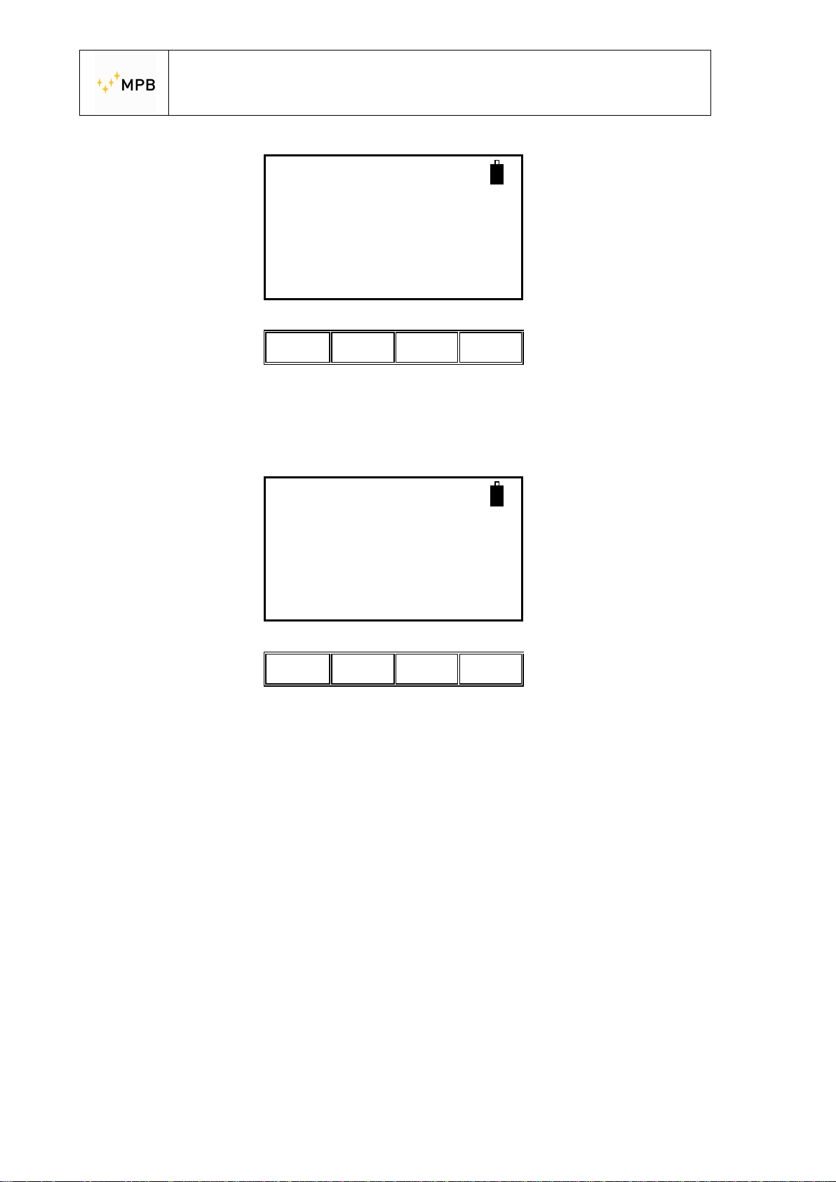
By pressing Meas the SEMS will start measuring the shielding effectiveness on the
selected frequency, displaying the current attenuation, along with the maximum and
minimum value in brackets.
144.210005 MHz
(112.4 : 134.4)
Att:120.1 dB
Stop Clear
ll ll ll ll
- 24 -
Page 25
USER’S MANUAL
S E M S
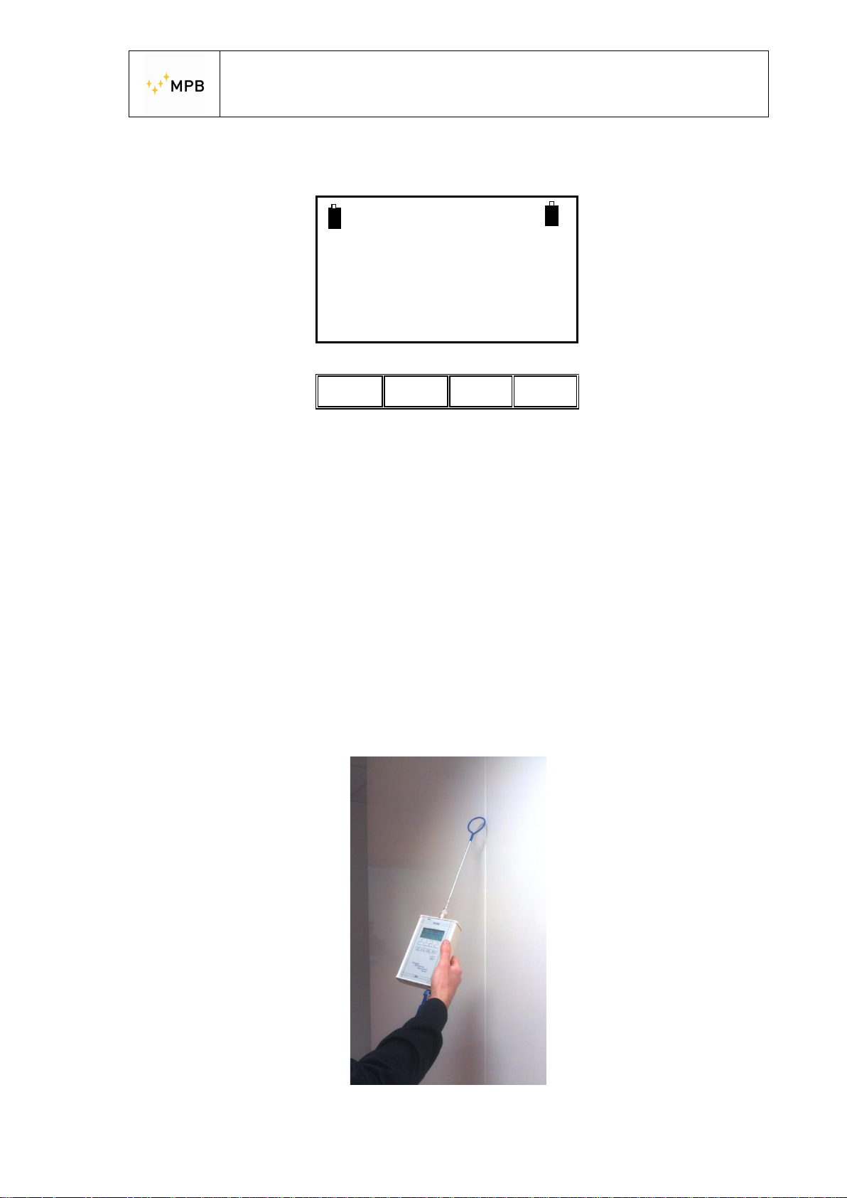
By pressing Clear the maximum and minimum values are reset, and by pressing
Stop you will halt the measure.
144.210005 MHz
Sniffing terminated
Meas Show Cal Snif
(112.4 : 134.4)
ll ll ll ll
By pressing Snif again you can restart the sniffing sequence or select a different
frequency.
Keep in mind that this operating mode can be successfully used in environments
where both the RS232\Wireless Adapter is unusable, allowing, along with the
Unconnected Mode (see the relative section in this manual), a full environmental
investigation.
The devices need to communicate only during the selection of the frequency. As
soon as the frequency is selected you will read the message “TX Tuned and
Ready”. From now on you can remove all the connections and start the
measurement.
You’ll need to restore the communication between TX and RX units only if you need
to change the working frequency.
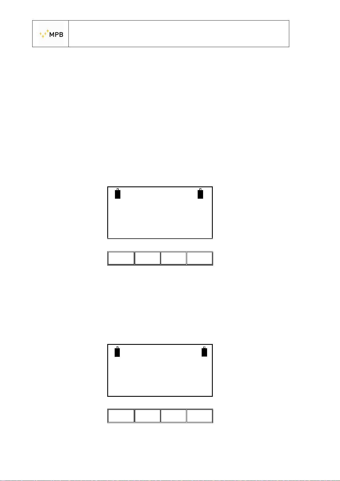
You can work with the sniffing mode with Loop Mod. L-3 antenna like in picture 7
Picture 7
- 25 -
Page 26
USER’S MANUAL
S E M S
3.3. WIZ menu
To improve the management of the measurement saving procedure you can use the
SEMS’s wizard for a better organization of data storage.
To use the wizard press the WIZ button in the top menu of the device. The wizard
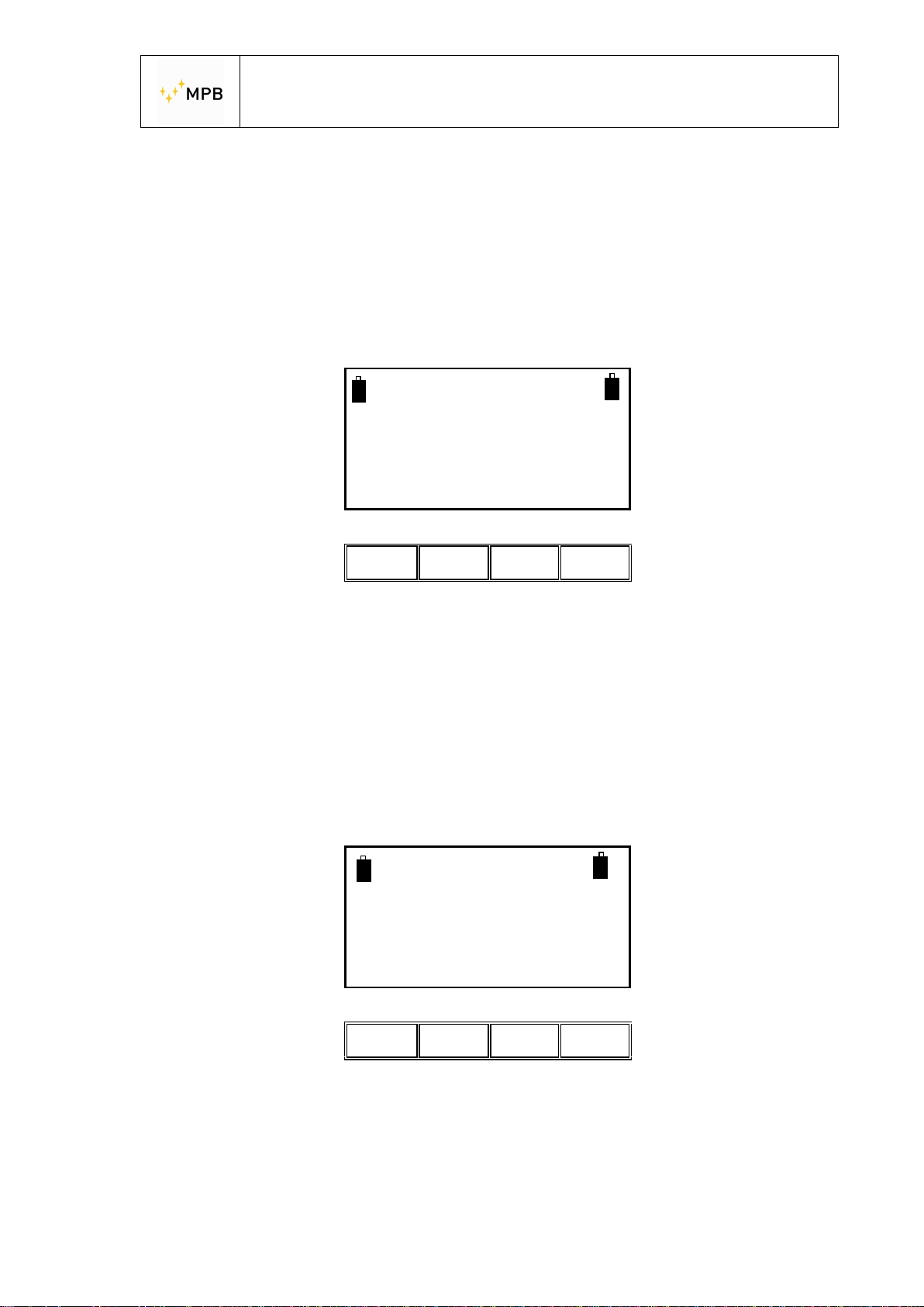
will lead the user throughout the procedure asking the following questions:
- The selection of the chamber where the measurements are performed (A, B,
C, D): Using A, B, C e D you can identify a shielded chamber. Then the user
has to remember the letter assigned to the chamber where the
measurements were done.
- Choice of the maximum number of spot to be measured (1, 2, 4, 8):
Represents the number of measuring spot assigned for each chamber. The
user must sort chronologically the measured spot and he will find the same
order in the instrument memory.
Choose the
Chamber you want
To measure
A B C D
ll ll ll ll
Select the max
number of spot
to be measured
1 2 4 8
ll ll ll ll
- 26 -
Page 27
USER’S MANUAL
S E M S
- The selection of ranges (antennas) to be measured (1, 2, 3, 4): it represents
the number of antennas systems available to the user during the
measurements. When you perform the measurements at all the points
specified previously, the system will switch range, asking you to replace the
antennas and redo the auto zero procedure.
Select the number
of ranges (antennas)
to be measured
1 2 4 8
ll ll ll ll
3.3.1. Measurement using wizard
After the selection of the chamber, spots and ranges the instrument will start the
procedure to perform the auto zero required by the first set of antennas to be used.
The procedure to follow for this purpose is exactly the same of the auto zero
calibration as described in chapter 3.2.1. of this manual.
Selecting “Scan” we can choose to zeroing the system using the default mode
(L_Lo - L_Hi - BIC) or to use the span programmable by the “SEMS PC_Utility”
software mode (User).
Choose the range
for Antenna 1
(Zero)
Scan List
ll ll ll Ll
- 27 -
Page 28
USER’S MANUAL
S E M S
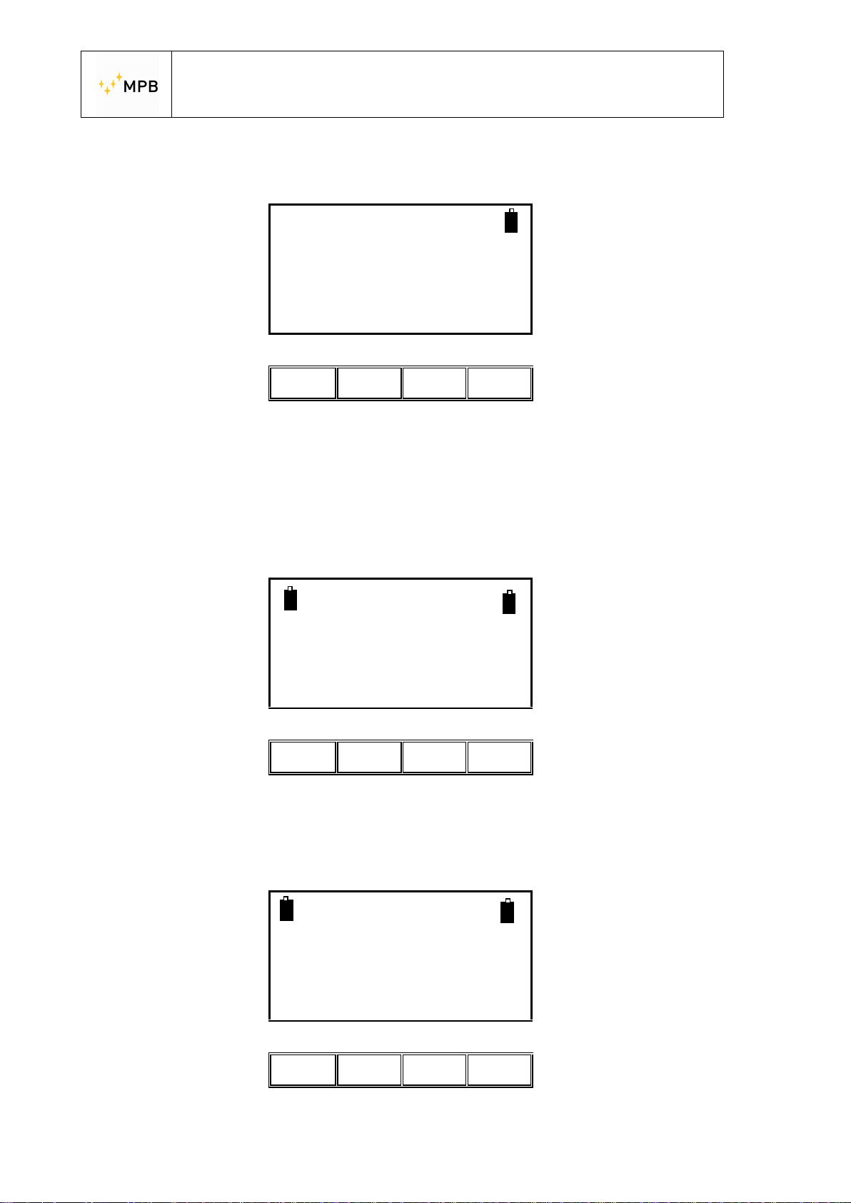
As soon as the zeroing procedure is completed, the measurement screenshot will
appear on the display.
In this screenshot the user has to decide how to perform the measurements:
automatically (Auto), or manually (Man).
Choosing the automatic mode we can make it start immediately (Now), or set a
fixed time countdown before starting (10s, 30s, e 60s).
Choose the range
for Antenna 1
(Zero)
L_Lo L_Hi Bic User
ll ll Ll ll
Fully Zeroed
Ready for Measuring
Auto Man PreQ
ll ll Ll ll
Fully Zeroed
Ready for Measuring
Now 10s 30s 60s
ll ll Ll ll
- 28 -
Page 29
USER’S MANUAL
S E M S
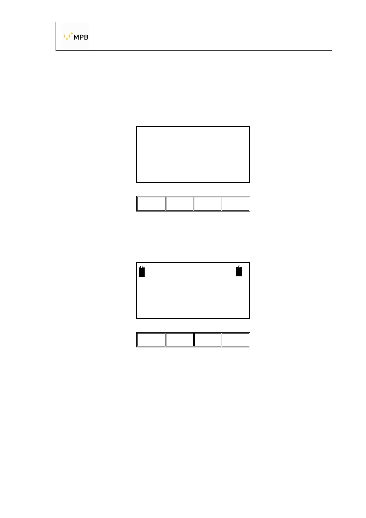
When the manual mode is selected , the user has to choose the commands: (Prev)
to measure the previous frequency, (Next) for the next frequency, (Redo) to repeat
the measurement on the current frequency or (Abort) to quit.
60.000000 MHz
Rbw:40 Hz.
Att: 65 dB
Prev Next Redo Abort
ll ll ll Ll
After this choice the measurement will be performed, and will appear the wizard
management screenshot to control the status of the procedure.
In this screenshot “Ch:A” means that the chosen chamber is called “A”, “Sp:1/2” is
the measurement spot index (in this case the spot is the 1st of the 2), “R:1/2” is the
antennas system (range) that we are using (in this case we are using the first
system of the 2).
“Spot Done” means that the measurement is completed for this spot with the
indicated range, the value shown nearby beneath brackets is the maximum
attenuation of the whole frequencies.
Ch:A Sp:1/2 R:1/2
Spot Done (115.7 dB)
Next Redo
End
ll ll ll Ll
- 29 -
Page 30

USER’S MANUAL
S E M S
The Next button must be pressed to get to the next spot. If all the required spot
have been measured, the procedure automatically switches to the next pair of
antennas and shows again the auto zeroing screenshot. If you used all the antennas
systems that you selected , the procedure is over and it will return to the main
screenshot with a success message about the data storing.
The Redo button repeats the measurement for the selected spot shown in the
screen, as soon as this operation is completed the display shows the same
screenshot with the updated value of the maximum attenuation.
The End button stops the measurements with the current set of antennas. By
pressing it the instrument will ask us to change the antennas and to start the auto
zero procedure, if the antennas systems have all been selected the procedure will
end with a message of success about the storing of the data and you will go back to
the main screenshot.
WARNING: Pressing the “End” button in the first antennas system will reduce the
spots for all the other systems. (e.g. if I select 8 spots and I measure just 3, pressing
end will reduce to 3 the maximum number of spot per system. But if we perform a
measurement on all of the 8 spots, then we will change antennas, and then again
we will press the end button after just 3 spots measured and all the 5 spots will be
kept.
- 30 -
Page 31
USER’S MANUAL
S E M S
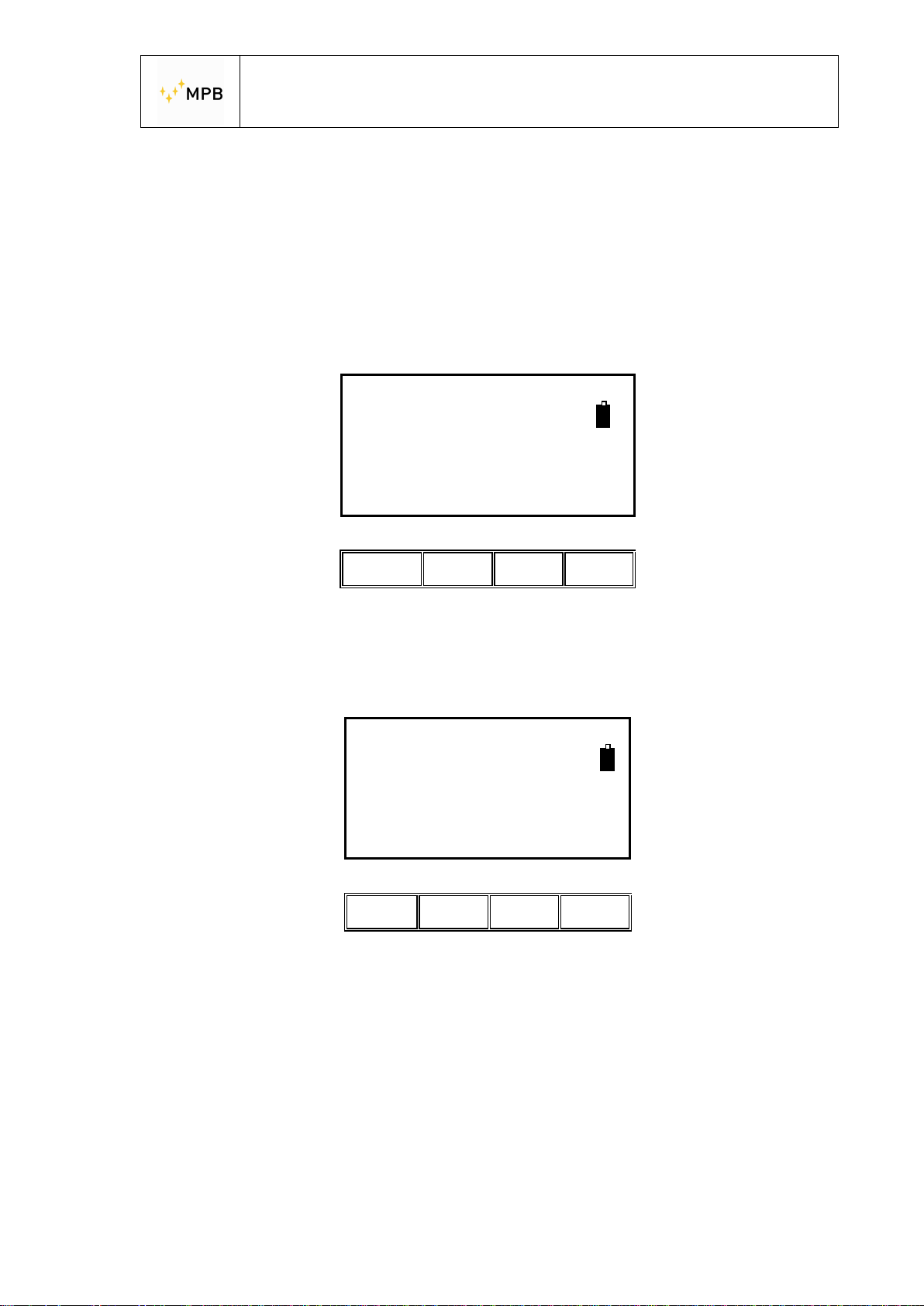
3.4. STP Menu
SEMS has an internal buzzer that beeps every time that a customizable alarm
threshold is exceeded.
To activate this function you have to press the “Stp” button in the main screenshot
shown as you turn the instrument on.
SEMS
FW – 1.32 27/03/14
HW-2
BEEP Clear
ll ll ll ll
and BEEP button
BEEP OFF 100dB
Use arrows for
10 dB step
+1 -1 ON OFF
ll ll ll Ll
Using the up and down arrows on the SEMS keyboard is possible to move the
threshold to 10 dB, to set a more fine value is possible to press the +1 and -1
buttons to increase or decrease the threshold to 1 dB.
By pressing the ON button the buzzer will be activated, and during the
measurements if the attenuation measured drops below the threshold the buzzer
will produce an acoustic signal. (Warning! This is a multifunction button. It’s
used also for the HiDyn Function)
- 31 -
Page 32
USER’S MANUAL
S E M S
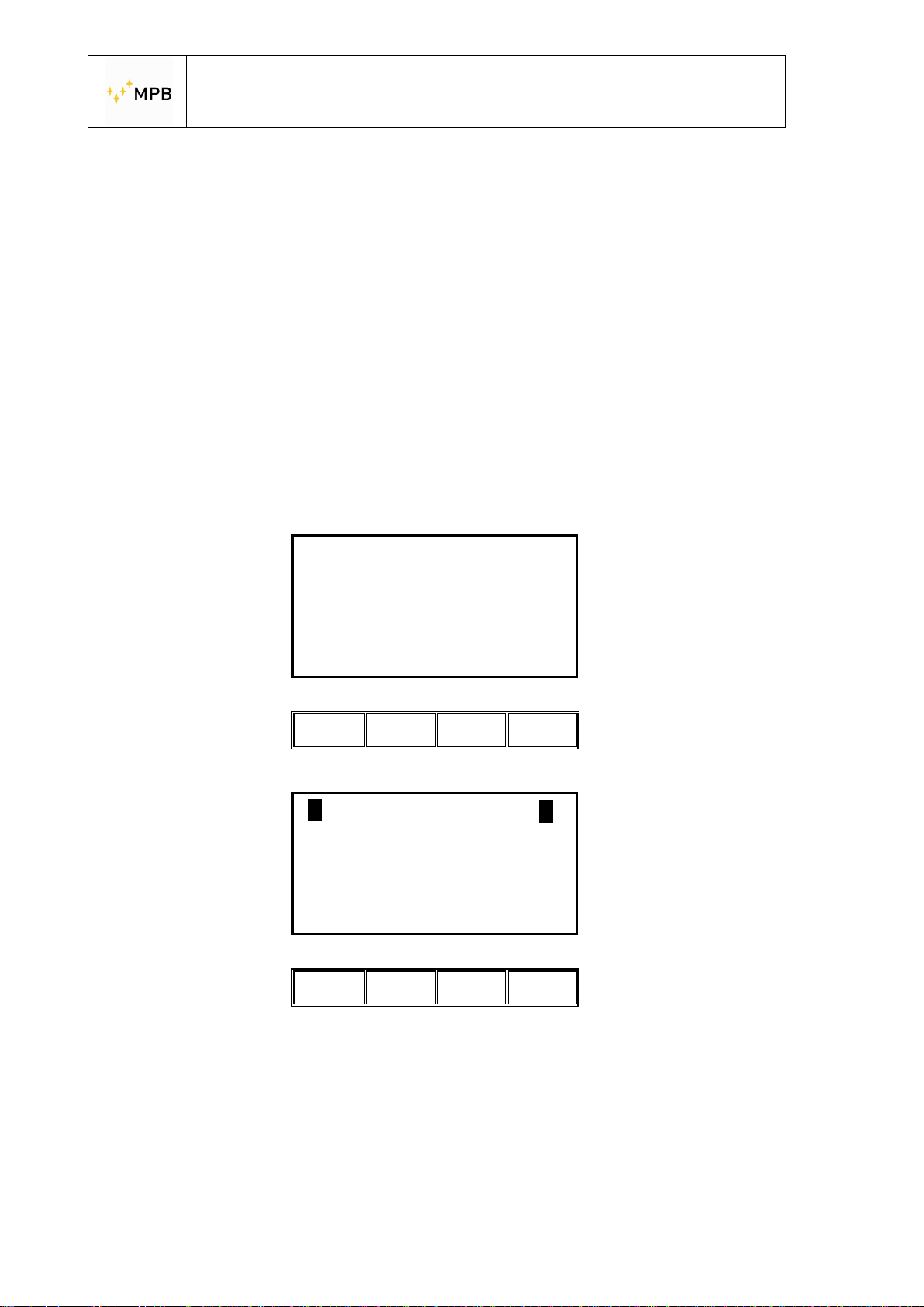
While the measured value remains under the threshold the buzzer will produce a
fast series of beeps, when the measured value returns over the threshold the buzzer
will be still beeping but with a slower series of sounds.
The OFF button will take the sound off.
The sound mode status is reported on the top of the display in this menu “BEEP
ON” and “BEEP OFF”.
The actual threshold is written on the right top of the screen (in this example is 100
dB)
Clear
With this function you can delete all the measure stored inside the RX unit
Pressing OK
WARNING
ALL Measures
Will be ERASED
Abort
OK
ll ll ll ll
Memory cleared
No measure Left
WIZ Std Stp
ll ll ll ll
- 32 -
Page 33

USER’S MANUAL
S E M S
3.5. Measuring the shielding attenuation
1) Place the receiver and the transmitter on the non conductive tripods (height 120
cm), and place them at a distance of 40/60 cm if you are using the loop antennas
and 100/200 cm if you are using biconical or dipole ones.
2) Connect the antennas upon the transmitter and receiver being careful to align
them in a parallel way.
3) Connect the wireless transducers to the RS232 port on the transmitter and the
receiver, turn on both devices and wait until the green blinking light stops and
remains turned on and the two icons of the batteries become visible on the
receiver’s display. Is recommended to wait a few minutes before going on
(warm-up).
4) Perform the zeroing procedure by using the Cal button, then select Scan or List
for the desired frequencies.(other z eroing mode is available to improve the
dynamic during measure. See Chapter HiDyn )
5) As soon as the zeroing procedure is over move the receiver into or out the
shielded environment near the first measurement point and the transmitter in the
opposite side trying to maintain the same distance used during the zeroing plus
the shield tickness.
6) Measure the attenuation pressing the Meas, Auto and 10s button to allow the
user to walk away f rom the measuring system.
7) As the measure ends save the result in a memory.
8) Repeat the 5, 6 and 7 steps for each measurement spot.
9) After all the spots are measured download the results on a PC using SEMS PC
Utility software provided with the product.
Configuration of the Key wireless Bluetooth
MASTER<<---- ON OFF -- -->>
ON 4 - OF F=115K ON=9600
ON 3 - AUTO MASTER
ON 2 - AUTO DISCOVER
OFF 1 - FACTORY DEFAULTS
SLAVE <<---- ON OFF ---->>
ON 4 - OF F=115K ON=9600
OFF 3 - AUTO MASTER
ON 2 - AUTO DISCOVER
OFF 1 - FACTORY DEFAULTS
- 33 -
Page 34
USER’S MANUAL
S E M S
3.6. Calibration using Calkit
The SEMS needs a periodic linear calibration, the Cal-Kit can easily and precisely
accomplish this purpose. If required the Cal-Kit can be provided with Accredia
calibration.
To start the calibration procedure press Std/Cal button from the main menu and
press CalK button, then calibration can be performed following the instructions on
the display.
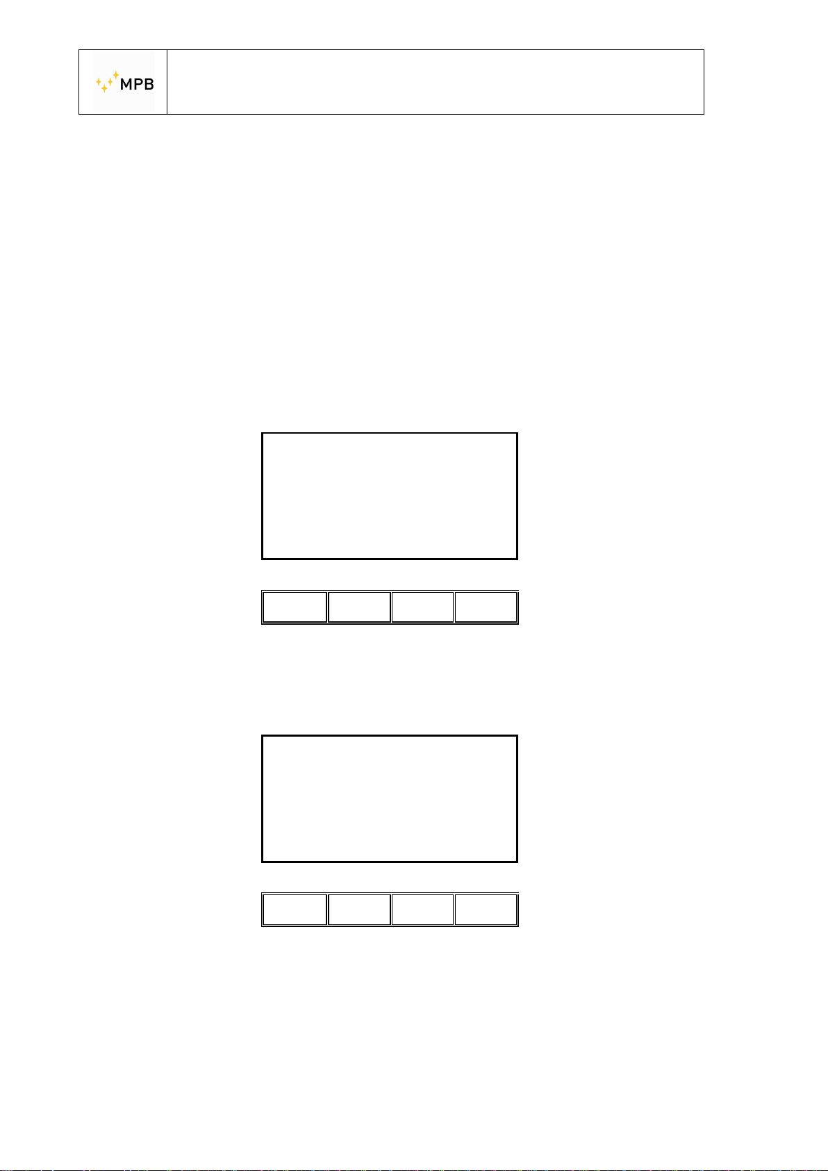
This screenshot shows the request for the 30 dB attenuator
Insert
30 dB Attenuator
HW-2
Connect the Tx and Rx using the 30 dB attenuator and press the OK button
This screenshot shows the request for the second attenuator
Abort
ll ll ll ll
Insert (2 X 30 dB)
OK
60 dB Attenuator
Abort
OK
Connect the second attenuator and then press the OK button
Repeat the same operation until you will use all the four 30 dB attenuators (4x30
dB= 120 dB)
- 34 -
ll ll ll ll
Page 35
USER’S MANUAL
S E M S
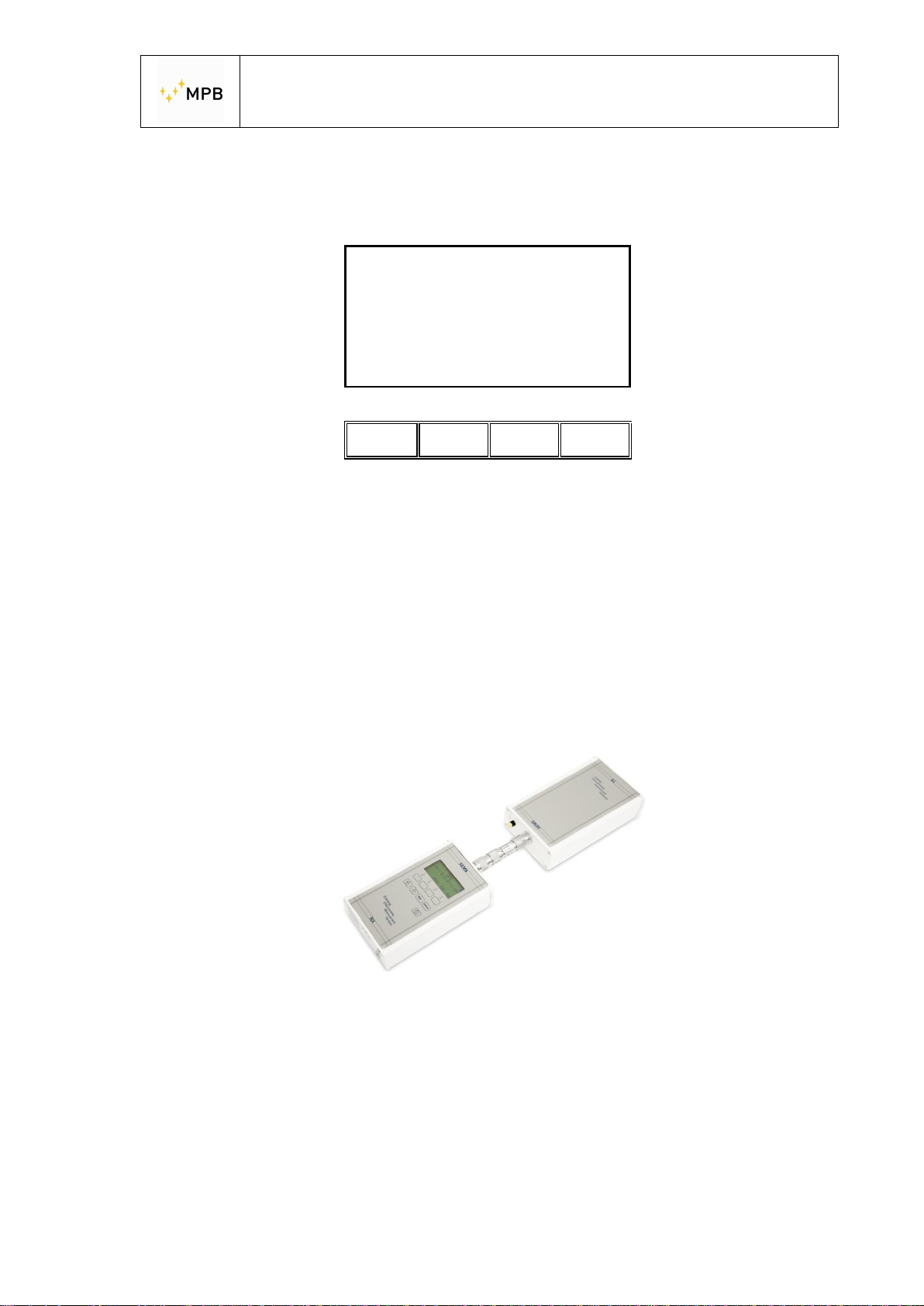
When the calibration is done the following screenshot will be shown
Calibration done
Worst: 0.70 dB
20.000 kHz (120 dB)
Show Cal
ll ll ll ll
The “Worst” parameter shows the worst accuracy over frequencies (in this case is
0.7 dB at 20.000kHz) typically is a parameter that you can find in the technical
specifications of the chamber:
10 kHz... 30MHz ± 1.0dB
30 MHz...300MHz ± 1.5dB
The following image show the procedure set-up.
Picture n°08
- 35 -
Page 36
USER’S MANUAL
S E M S
3.7. Measurement with Rod antennas mod. R1
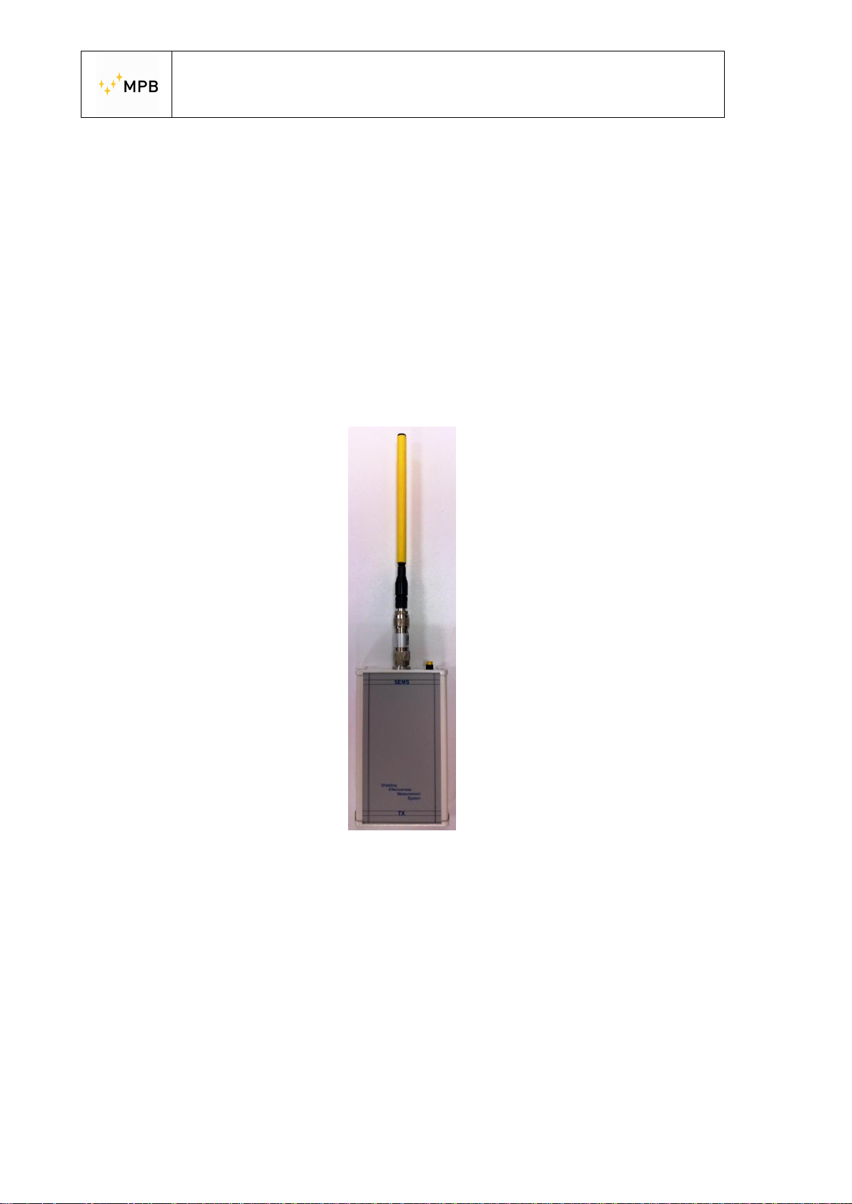
When using Rod antennas( in the zero setting and in the measurement phase) it’s
absolutely necessary to connect the SEMS TX 10 dB attenuator ,already supplied,
before connecting the Rod antenna (picture n.09)
WARNING: not using the attenuator can cause serious troubles to the system
functionality.
Picture n°09
- 36 -
Page 37
USER’S MANUAL
S E M S
3.9. Unconnected Mode
Some measurement applications are not suited for the usage of the RS232\Wireless
Bluetooth key or the Optical Link Mod. LO.
An example could be a measurement in a shielded environment with no waveguides
on technical panels
For those kind of applications there’s a specific operating mode called Unconnected.
In this operating mode, during the measurement, there’s no need of a connection
between the RX and TX unit.
To use this operating mode the SEMS RX must be programmed (through the
SEMS Software) with a specific list of no more than 20 frequencies.
The list can be saved in any of the three L1-3 slots.
The Unconnected mode can be used either in the Wizard or in the Standard mode.
To use it in Standard mode select Std from the home menu:
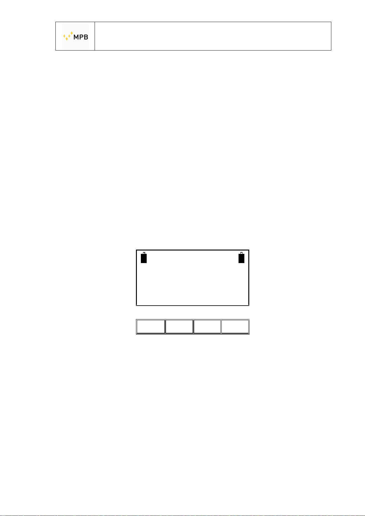
SEMS
FW – 1.31 27/03/14
HW-2
Press Cal, then List and then select the list where you saved the frequencies for the
unconnected mode. Proceed with the zeroing sequence as you would do for a
normal measurement.
WIZ Std Stp
ll ll ll ll
- 37 -
Page 38
USER’S MANUAL
S E M S
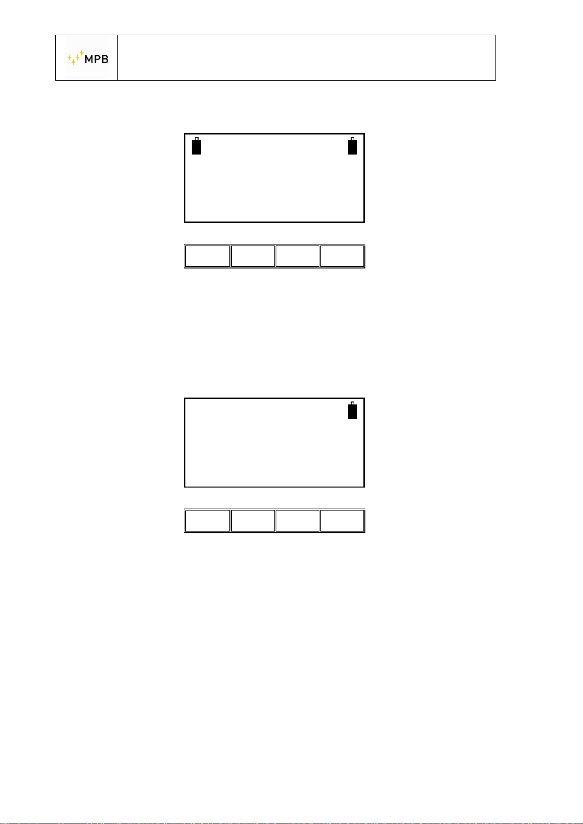
As soon as the zeroing sequence ends press Meas:
SEMS
Ready for Measuring
Place the TX and RX units in the desired measurement spot and press the Unc
button to enable the two units to synchronize their internal clock.
Note that you have to make this step while the 2 batteries are visible on the LCD
display
Auto Man PreQ Unc
ll ll ll Il
Remove
Connections
and start measuring
Now 10s 30s 60s
ll ll ll Il
Now you can remove the RS232\Wireless adapter from the RX unit (you’ll see the
battery icon of the TX Unit that disappears), close the door of the shielded
environment and start measuring.
- 38 -
Page 39
USER’S MANUAL
S E M S
You’ll see a countdown starting from a value that can vary according to the moment
in which you started the measurement and the number of frequencies you entered
in the list.
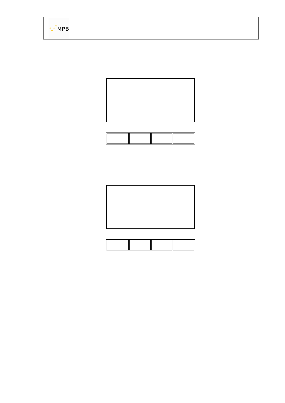
5.000000 MHz
Sync in 12 s
After the first measurement you’ll see that before each frequency there is a
synchronization delay.
Abort
ll ll ll ll
10.000000 MHz
Sync in 2 s
Abort
ll ll ll ll
Att:88.0 dB
As soon as the measurement ends you can save the data in a memory slot just like
in a normal Standard measurement.
- 39 -
Page 40
USER’S MANUAL
S E M S
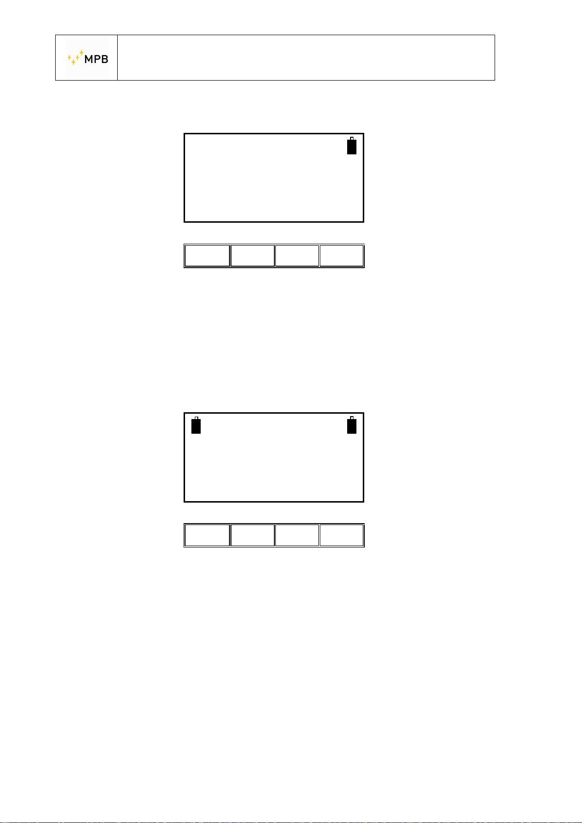
If you need, you can start another measurement by selecting Meas again:
SEMS
Ready for Measuring
By pressing Auto you can begin a new measurement without reconnecting the two
units. However, you can do this only for a fixed period of time (see below).
The usage of this mode in a Wizard measurement works in a very similar way.
You can start a wizard zeroing sequence by selecting the list you programmed for
the unconnected mode as the only range.
Auto
ll ll ll Il
Fully Zeroed
Ready for Measuring
Auto Man PreQ Unc
ll ll ll Il
- 40 -
Page 41
USER’S MANUAL
S E M S
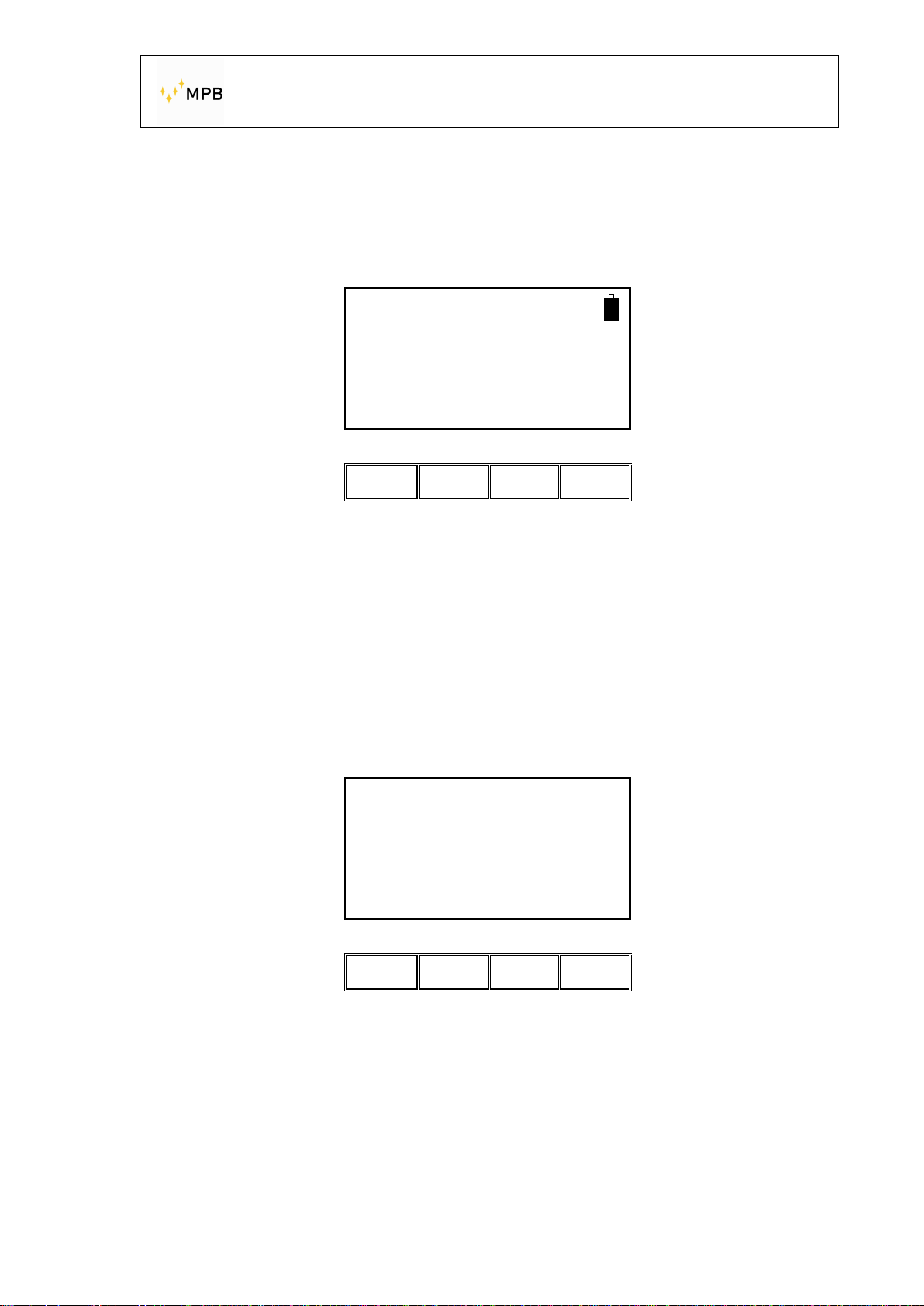
Place the TX and RX units in the desired measurement spots and press the Unc
button to enable the two units to synchronize their internal clock.
Note that you have to make this step while the 2 batteries are visible on the LCD
display
Remove
Connections
Now you can remove the RS232\Wireless adapter from the RX unit (you’ll see the
battery icon of the T X Unit that disappears), close the door of the shielded
environment and start measuring.
You’ll see a countdown starting from a value that can vary according to the moment
in which you started the measurement and the number of frequencies you entered
in the list.
and start measuring
Now 10s 30s 60s
ll ll ll ll
Abort
5.000000 MHz
Sync in 12 s
ll ll ll ll
- 41 -
Page 42
USER’S MANUAL
S E M S
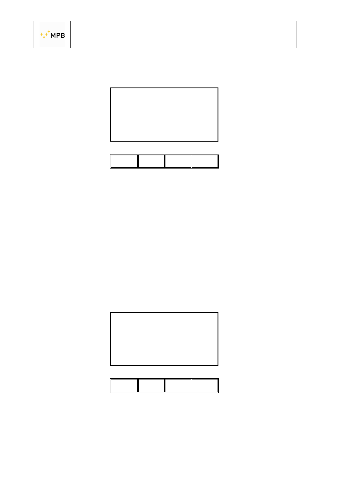
After the first measurement you’ll see that before each frequency there is a
synchronization delay.
10.000000 MHz
Sync in 2 s
Abort
ll ll ll Il
Att:88.0 dB
As soon as the measurement ends you’ll see the usual “Spot Done” screen from
Wizard mode, where you can repeat the measurement (ReDo) or start measuring
the next (if there is one) spot (Next).
In both Standard and Wizard mode you have a limited time to make the
measurements before reconnecting the RX and TX unit.
This time limit is used to avoid measurement errors imputable to long term clock
delays.
The timer starts from the moment in which you press the Unc button.
After 14 minutes, if you start a measurement, you will be prompted to reconnect the
TX and RX unit to recalibrate the internal clocks.
Re-Sync Needed
Connect RX-TX
Abort
then press OK
OK
ll ll ll Il
At this point you must reconnect the RS232\Wireless adapter, wait for the steady
green light to appear and then press OK.
- 42 -
Page 43
USER’S MANUAL
S E M S
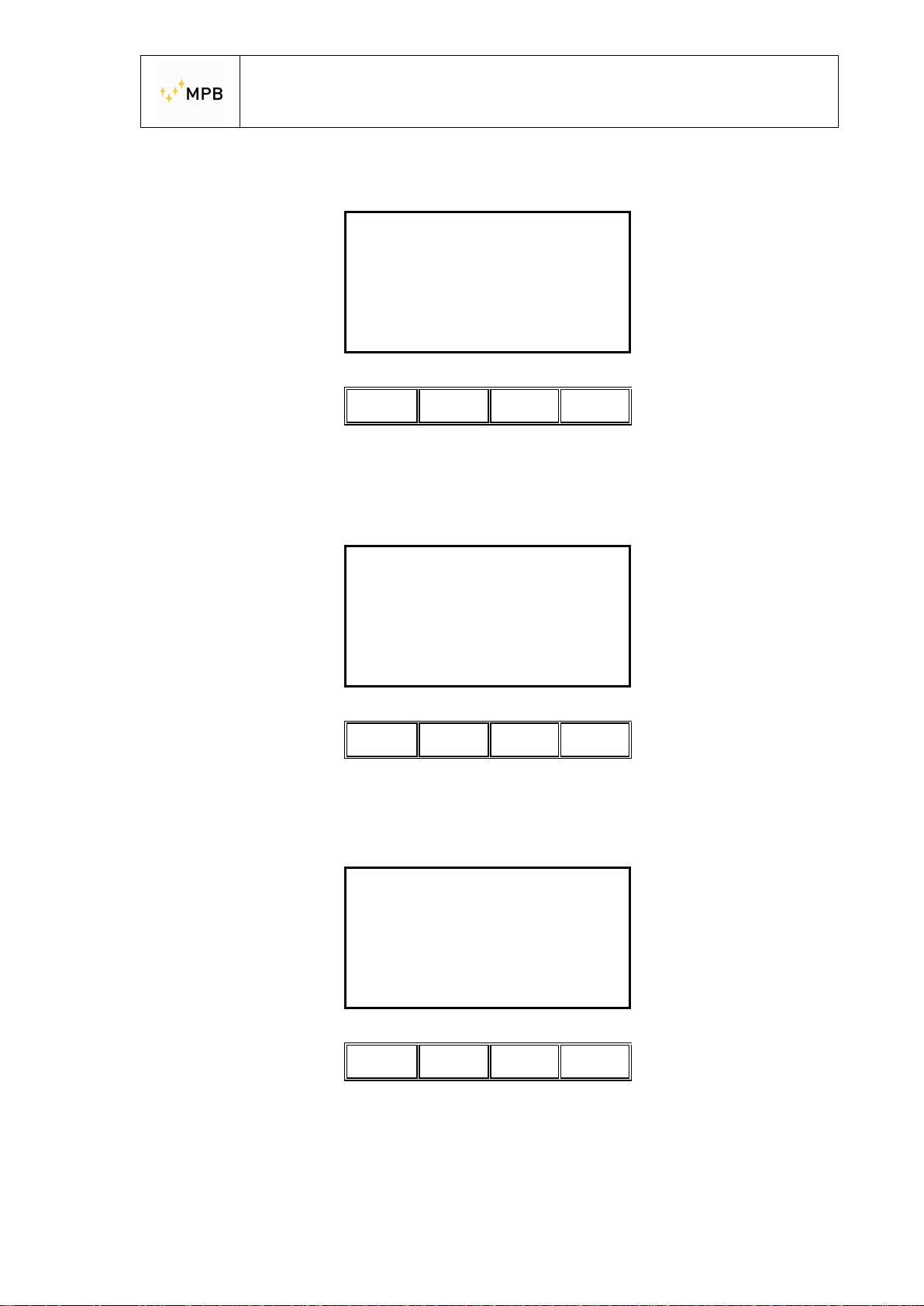
If the connection is successful you’ll see the following screen:
Sync OK
Remove
Abort
ll ll ll ll
Connections
OK
Now you are able to start the measurement, the 14 minutes timer is restarted. If the
connection fails (keep in mind that after 17 minutes the TX Unit turns off
automatically) you will see the following screen:
Synchronizing
Transmitter
Abort
ll ll ll ll
OK
And after pressing OK:
Could not Sync
Failed
Abort
Is TX connected?
OK
ll ll ll ll
In this case, check the TX connection and if needed turn on the unit. Then, try again
by pressing OK.
- 43 -
Page 44
USER’S MANUAL
S E M S
3.9. Prequiet Mode
Some shielded environments are naturally noisy. The background noise of the
environment can affect the quality of the measurement itself.
To avoid this the SEMS has a cleaning function called Prequiet Mode.
In the Prequiet Mode the SEMS RX modifies the working frequencies so that the
environmental noise is kept out of the measurement points.
The Prequiet mode is available in both Wizard and Standard mode, but it can’t be
used together with Unconnected mode.
In both cases, you have to do the zeroing of the system , then, in the Meas menu,
you’ll find the PreQ button.
In Standard mode:
And in Wizard mode:
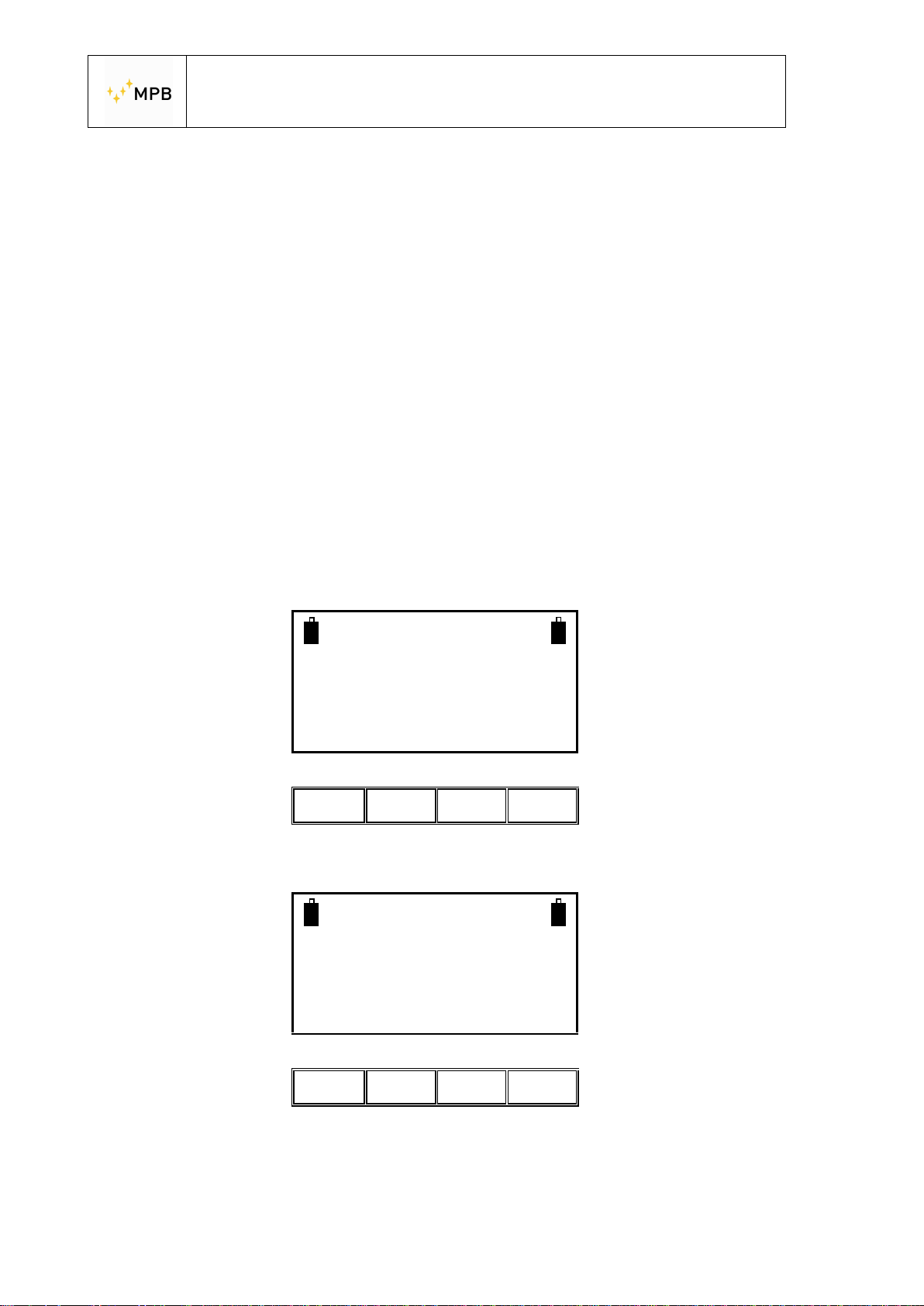
SEMS
Ready for Measuring
Auto Man PreQ Unc
ll ll ll Il
Fully Zeroed
Ready for Measuring
Auto Man PreQ Unc
ll ll ll Il
- 44 -
Page 45
USER’S MANUAL
S E M S
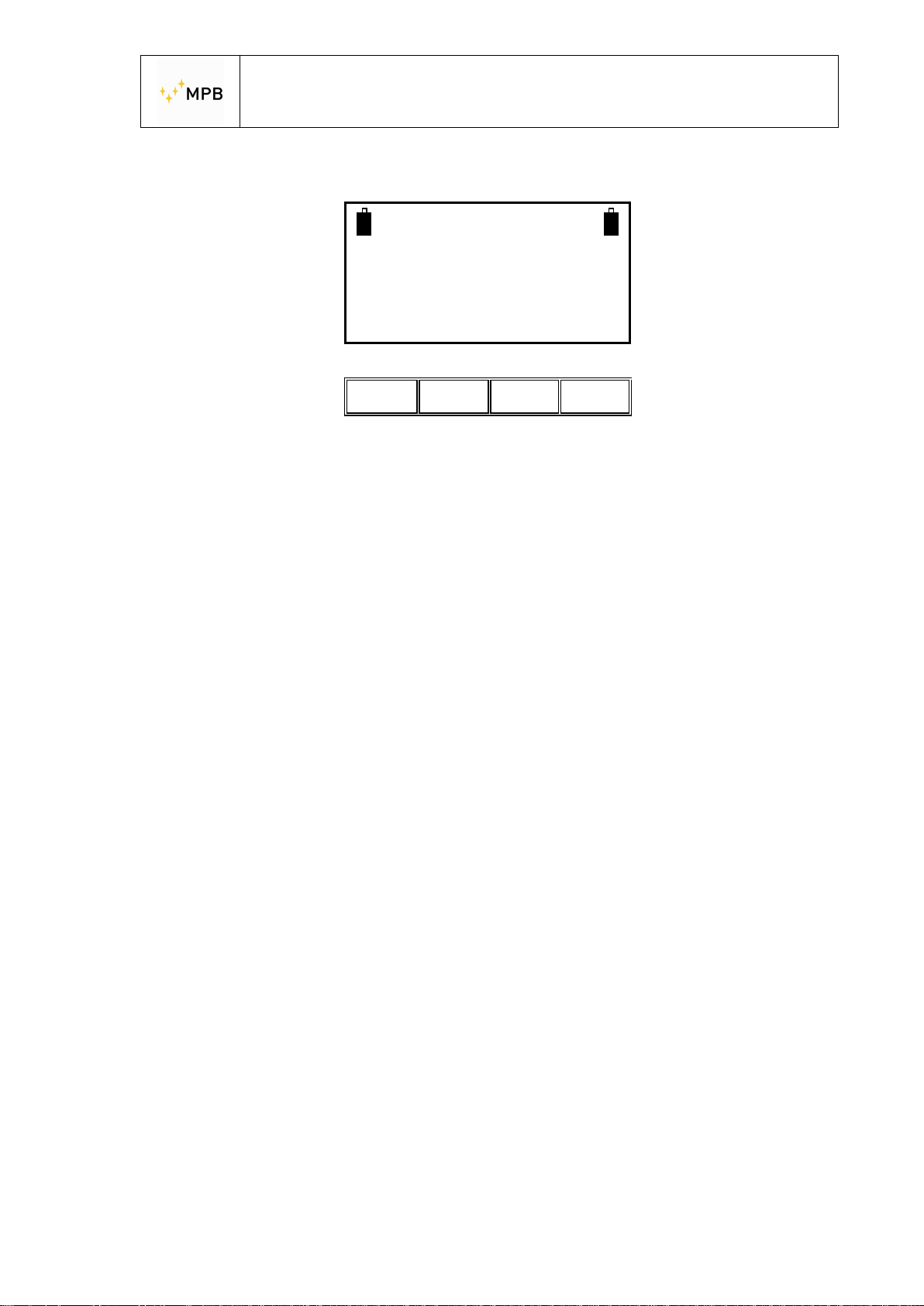
As soon as the quieting procedure finishes you can start the measurement.
Quieting
Terminated
Meas Show Cal Snif
ll ll ll ll
By pressing Meas and starting a measure, the SEMS will automatically use the
optimized frequency list.
- 45 -
Page 46
USER’S MANUAL
S E M S
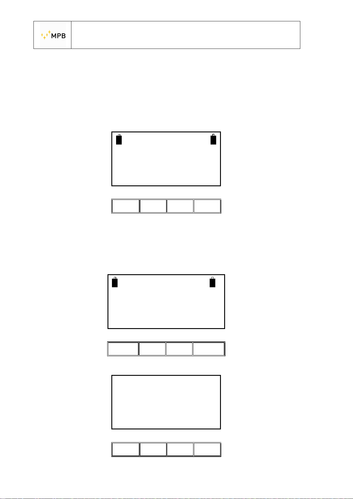
3.10. SEMS LIGHT
When you start on the RX unit the display will show
SEMS
FW – 1.32 27/03/14
HW-Light
The SEMS LIGHT has the same functions and performances than SEMS.
The only limit is on the max frequency until 96 MHz
In the Stp menu it’s possible upgrade the RX Unit (through the activating code )
from SEMS LIGHT to SEMS,so you can working until 300 MHz.
WIZ Std Cal Stp
Il ll ll Il
SEMS
FW – 1.32 27/03/14
HW-Light
BEEP Clear Code0
Il ll ll Il
Note: The activating Code is an option Mod. Key-300
Please enter CODE
Enter to confirm
*
- 46 -
0 1 2 3
Il ll ll Il
Page 47
USER’S MANUAL
S E M S
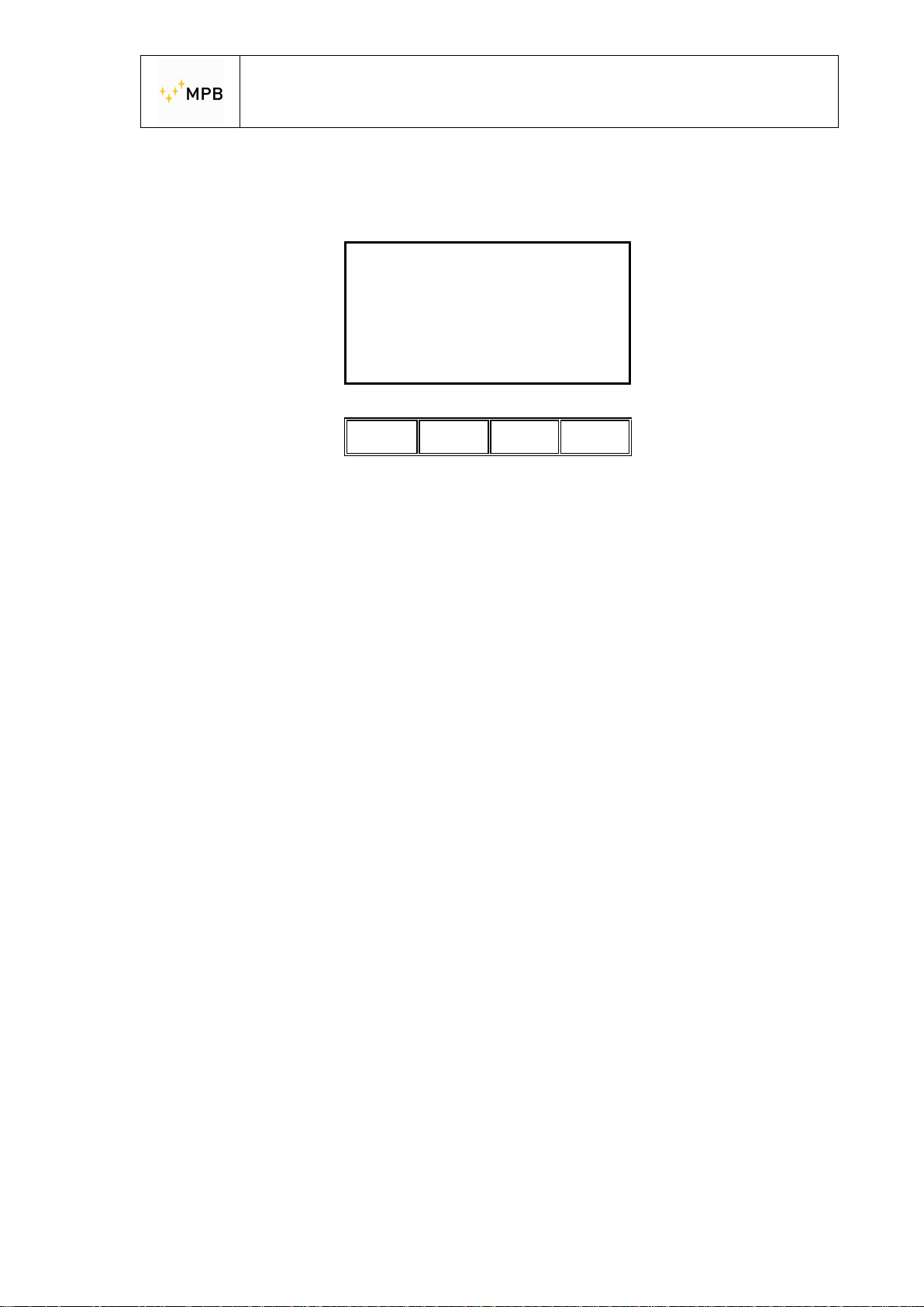
After you unlock the SEMS LIGHT the display will show:
Code saved
Turn the SEMS
OFF then on again
And then you will be ready to measure until 300 MHz.
Abort
Il ll ll Il
OK
- 47 -
Page 48
USER’S MANUAL
S E M S
4. SEMS PC Utility software, controls and
functions
4.1. Installation
4.2.
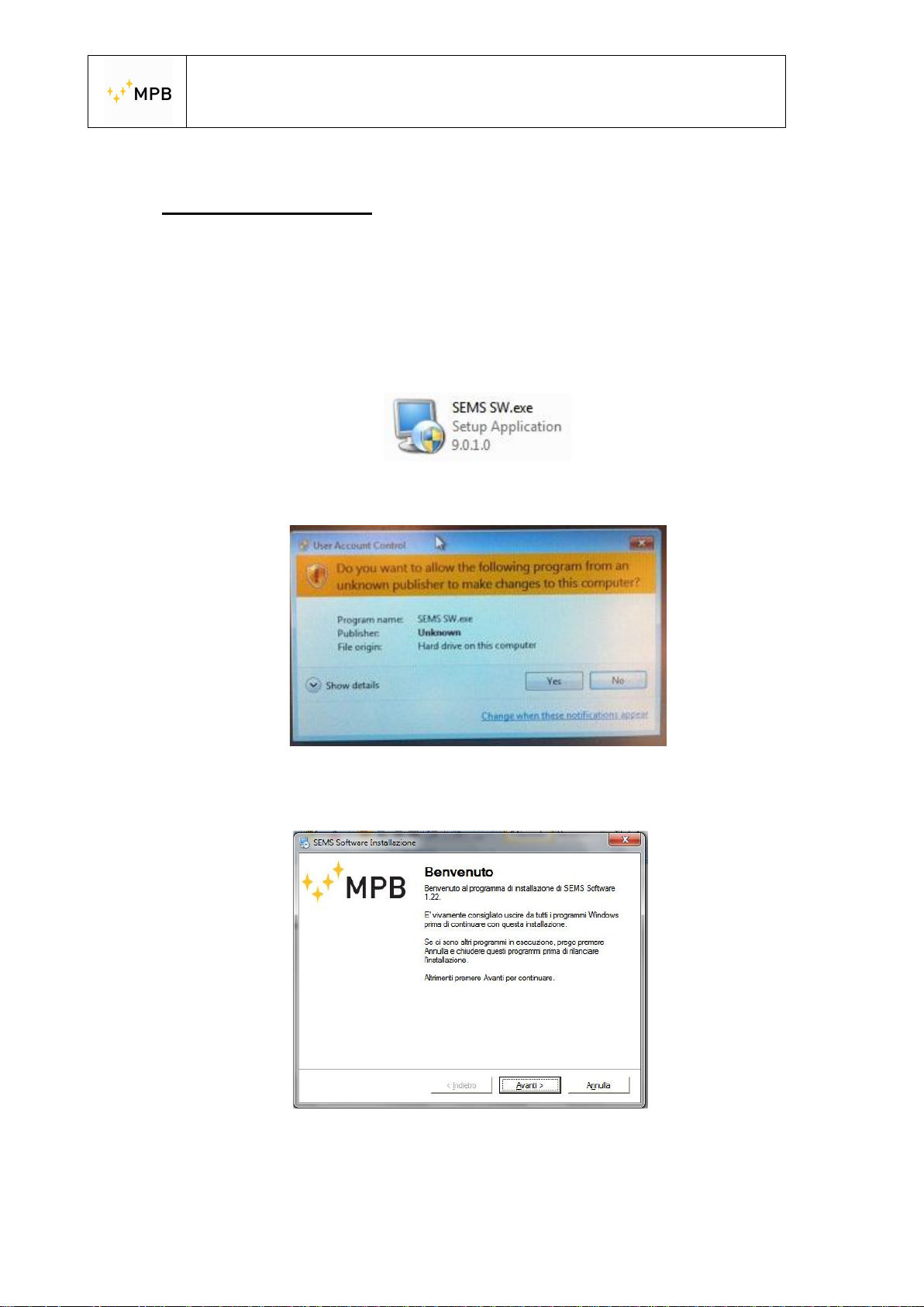
Insert the USB Drive that came along with your SEMS system into the PC you
are installing the software to.
Launch the setup file (SEMS SW.exe) and click YES in the pop up window (Vista
and Seven users only):
According to your computer settings, SEMS SW Installer will have on screen
instruction in different language.
Follow the instructions on screen to complete the installation.
Be carefull: For the OS Windows 7 and upper you must launch the SEMS SW
with all administrator permission.
- 48 -
Page 49
USER’S MANUAL
S E M S
4.2. Connecting the instrument
1) Plug the USB to Serial adapter to your computer.
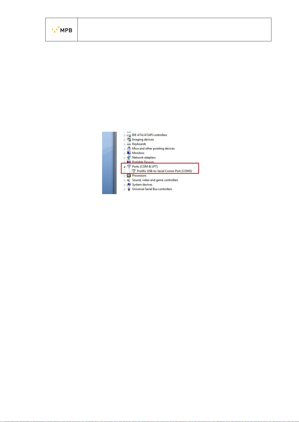
2) Under Windows Seven, press Start, go in Control Panel, then Hardware and
Sound, then Device Manager.
3) Under Windows XP press Start, go in Control Panel, then System, then
Hardware, then Device Manager.
4) Take note of the COM port where the USB to Serial interface is mapped (I.E.
COM3):
5) Connect the SEMS RX to the RS232 connector and turn on the unit.
6) Start the SEMS SW from the desktop shortcut or your start menu.
7) Open the “Option” menu, click on “Select Comm” and in the new window
insert the number you’ve taken note before. Press the Enter key on your
keyboard to confirm.
The program should be now correctly configured to communicate with the SEMS RX
unit.
Note: Please use the driver version that comes with the SEMS for the USB to Serial
interface.
- 49 -
Page 50
USER’S MANUAL
S E M S
4.3. Retrieving a measurement
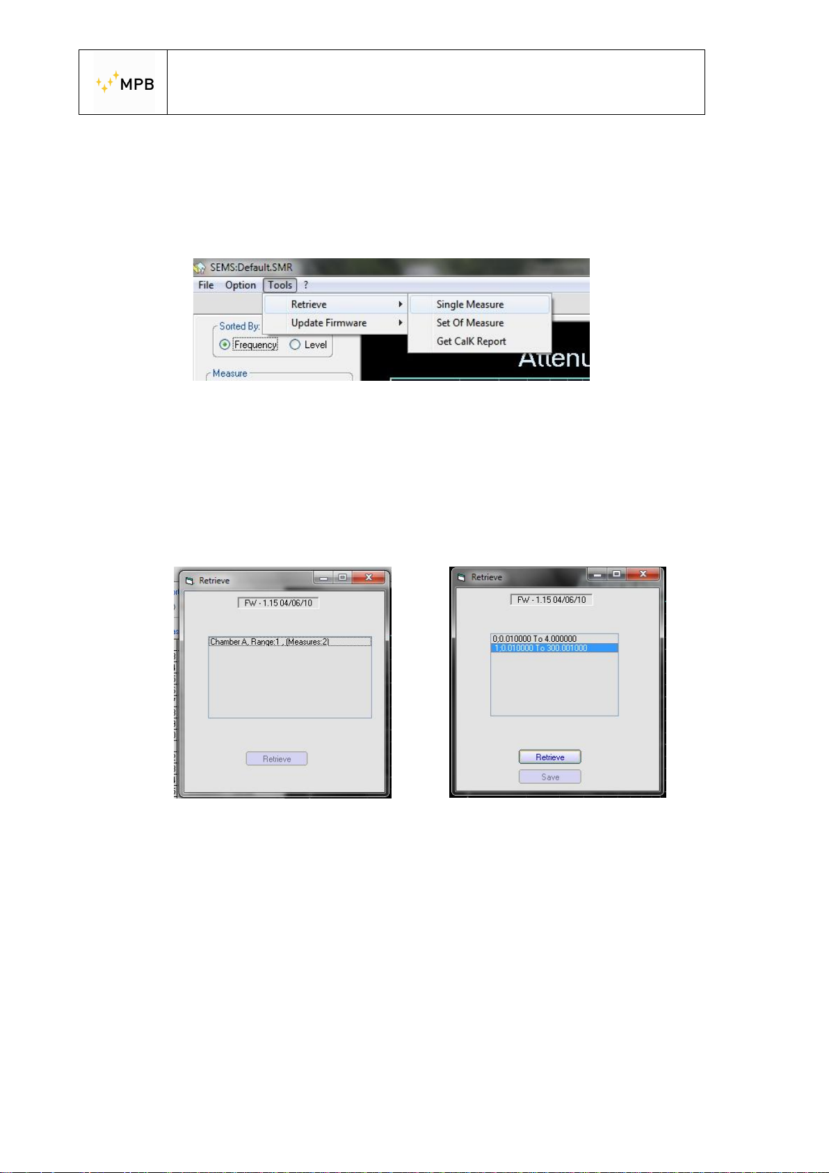
Through the Tools menu you can access different functions to query the RX unit.
· Single Measure will download a single measurement previously stored in the
SEMS memory.
· Set of Measure will download data relative to a specific room data set.
· Get CalK Report will download data relative to the calibration procedure (a
TXT file with the report will be created).
By clicking on the desired element and then pressing Retrieve data will be
downloaded from the SEMS internal memory and shown on the main window (you
will be asked to save an optional record file for latter reference)
- 50 -
Page 51
USER’S MANUAL
S E M S
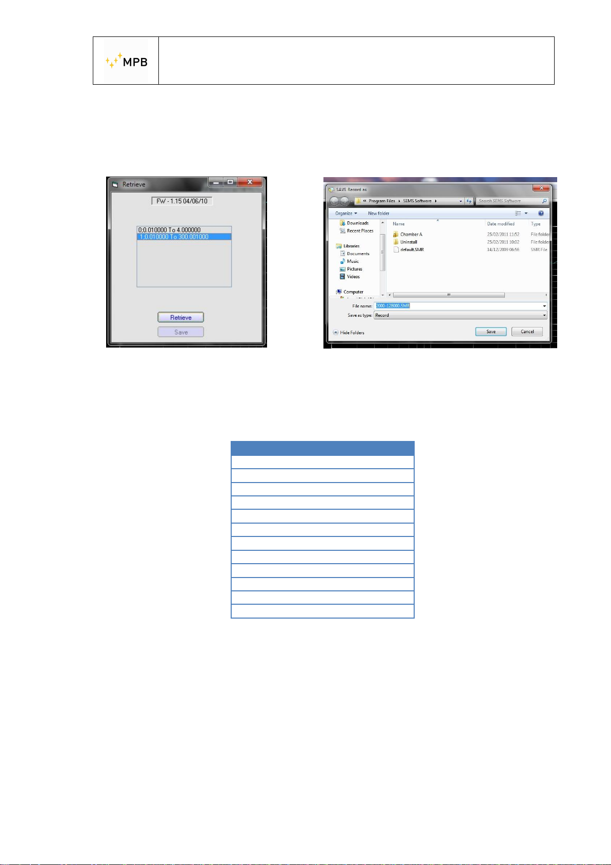
To retrieve a single measure access the option from the relative menu (Tools ->
Retrieve -> Single Measure) and select the desired measure from the popup
window:
Clicking retrieve will update data currently shown on the screen with the retrieved
measure and allows you to save the measure as a record file (SMR).
To correlate the memory slot to the index of the measure, you can refer to the
following table.
Memory Slot Index
L1 0
L2 1
L3 2
L4 3
M1 8
M2 9
M3 10
M4 11
H1 16
H2 17
H3 18
H4 19
To consult this measure again, just use the Load button from the File menu and
select the relative record file.
- 51 -
Page 52
USER’S MANUAL
S E M S
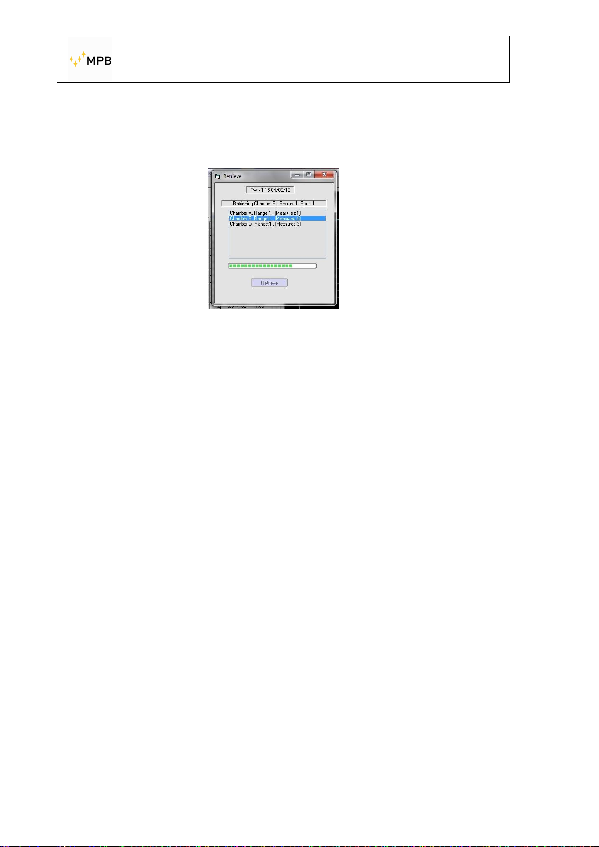
Retrieving a set of measures works in a similar fashion.
To retrieve all data relative to a chamber you have to click on Retrieve -> Set of
Measure from the Tools menu, then select the dataset from the pop up window.
In this example, we are retrieving data from Chamber B, Range 1.
As you can see the window is showing the number of measures relative to each set
(in this case, 4 different spots)
- 52 -
Page 53
USER’S MANUAL
S E M S
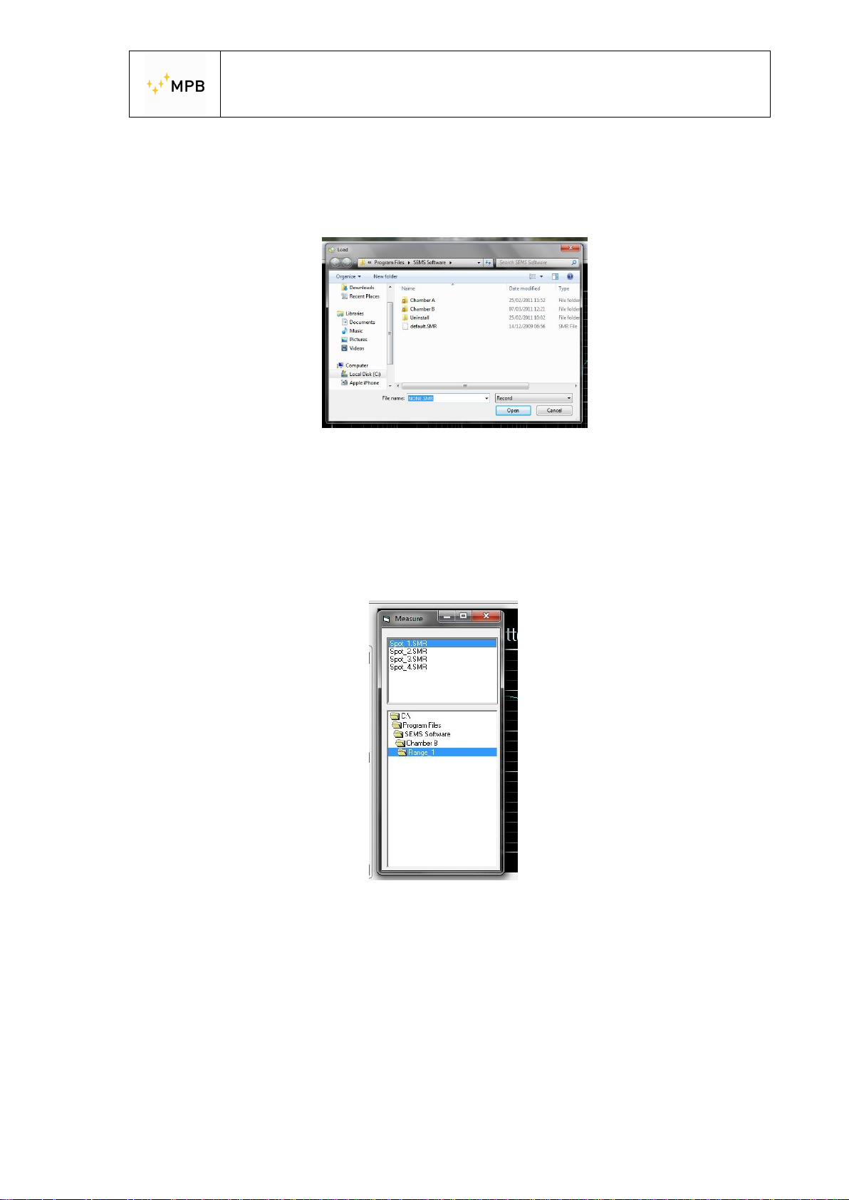
As the download finishes you are not prompted to save your data: this is because
SEMS automatically saves sets of measures inside its own work folder.
To consult all data inherent to the chamber, just click File -> Load
Inside “Chamber B” folder you will find, organized in subfolders relative to the
antenna (Range) used, all the measurement spots.
By selecting one of the SMR files the main window updates data with the one
relative to the spot selected.
In addition, a new window appears to allow easy navigation between the
measurement spots:
In the lower part of this window you can navigate through the work folder and select
the desired chamber\range, in the top part of the window the measurement spots
contained in the relative folder are shown.
You can select one of these spot and update the data shown on the main window by
single-clicking it.
- 53 -
Page 54
USER’S MANUAL
S E M S
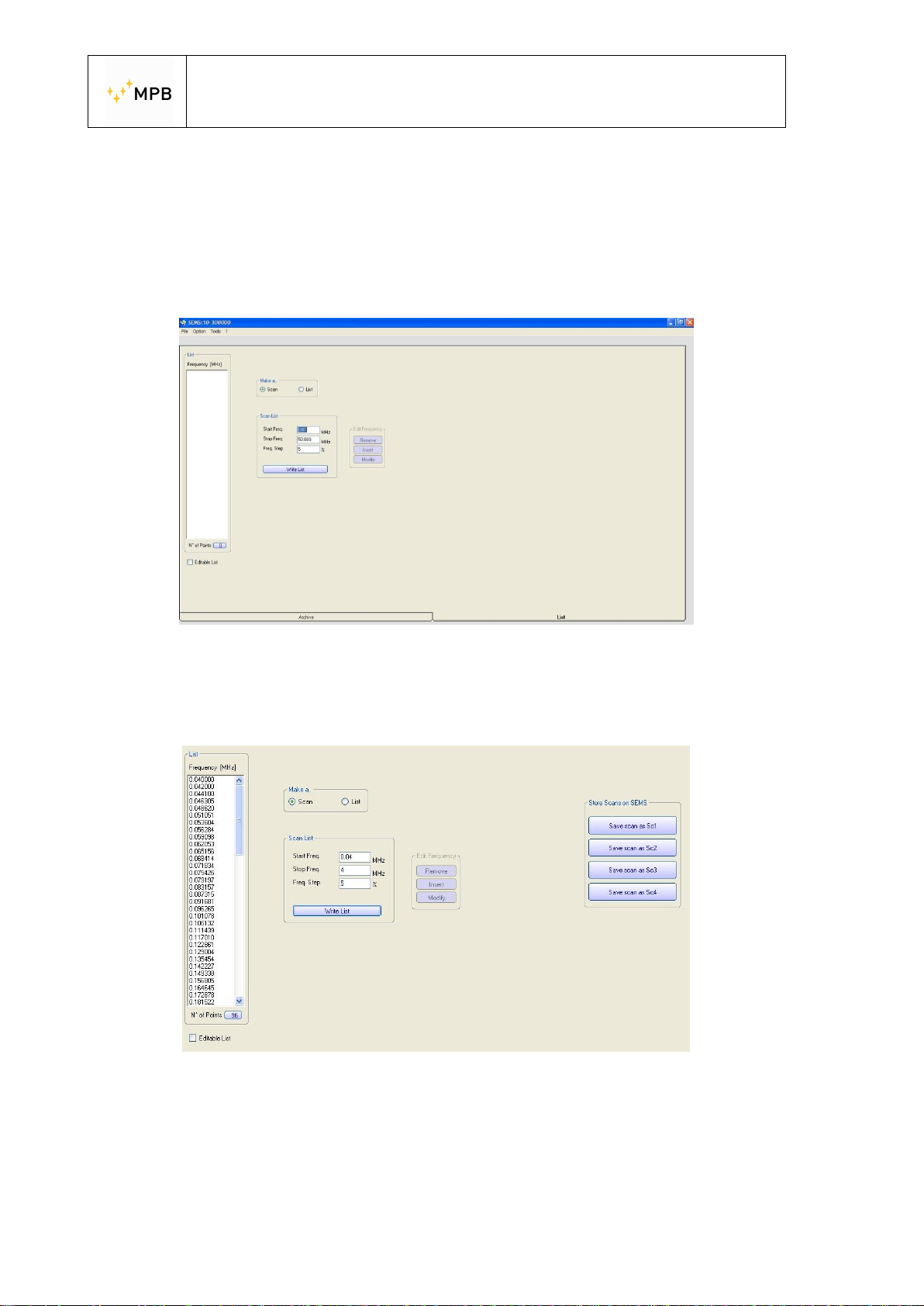
4.4. Programming a frequencies list with List or Scan
In the menu List, of the SEMS PC Software, it’s possible programming a list of
frequencies or a scanning and store them inside RX unit:
The picture below is the menu for programming
If you want use the Scanning you must select the start/stop frequency and choose
the step in percentage
To make a table list, you must click on the “Write List” button
And then store it inside the RX Unit, clicking on one of the four available memories
- 54 -
Page 55
USER’S MANUAL
S E M S
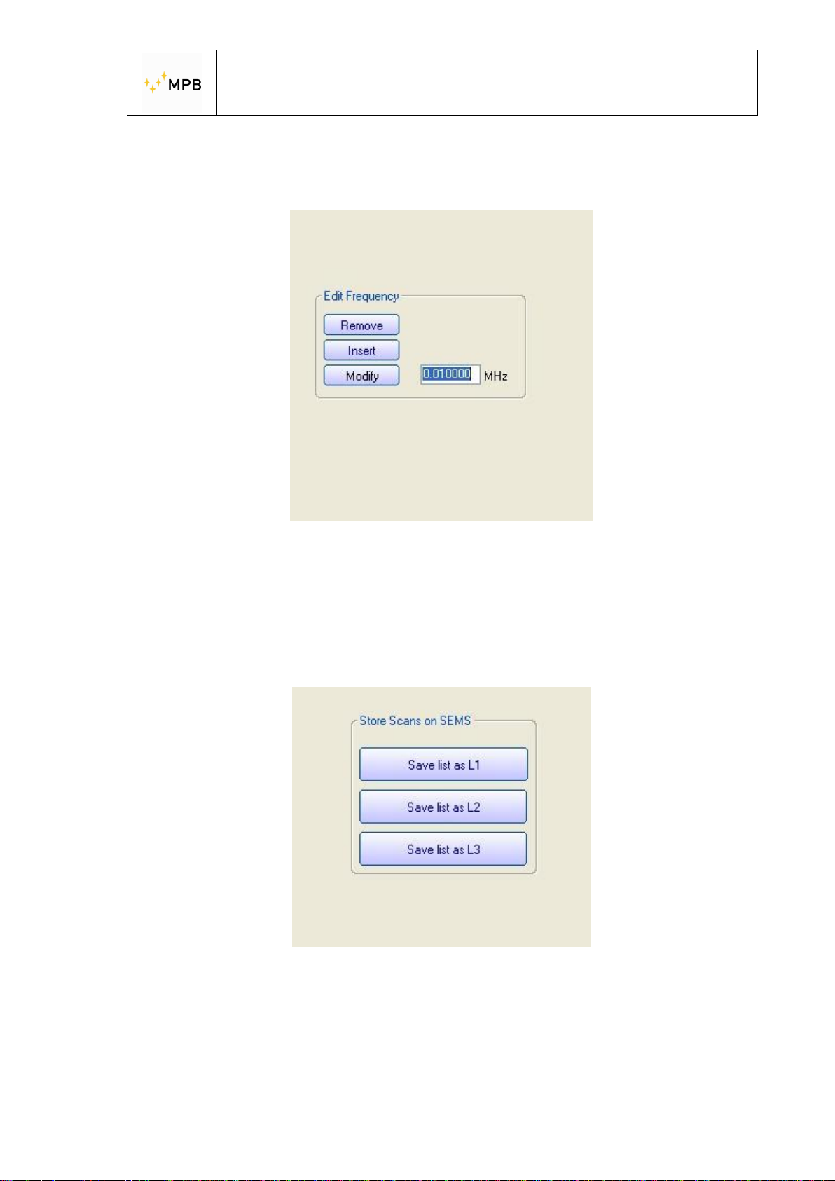
Otherwise, if you want to make a frequencies list, just click in the “List” and edit the
frequency
To make a frequencies List, you must select the “Insert” button, write the frequency
value in the near area and push again the “insert” button.
Proceed in the same way to modify or remove a frequency value.
You must insert minimum three frequencies to enable the box below:
Proceed to save the data inside the RX unit, clicking on one of the three button
- 55 -
Page 56

USER’S MANUAL
S E M S
Note:
During programming, to enable the functions:
“Unconnected Mode” Make max 20 Frequencies
“HiDyn-Mode Make max 30 Frequencies
- 56 -
Page 57
USER’S MANUAL
S E M S
4.5. Working with the results
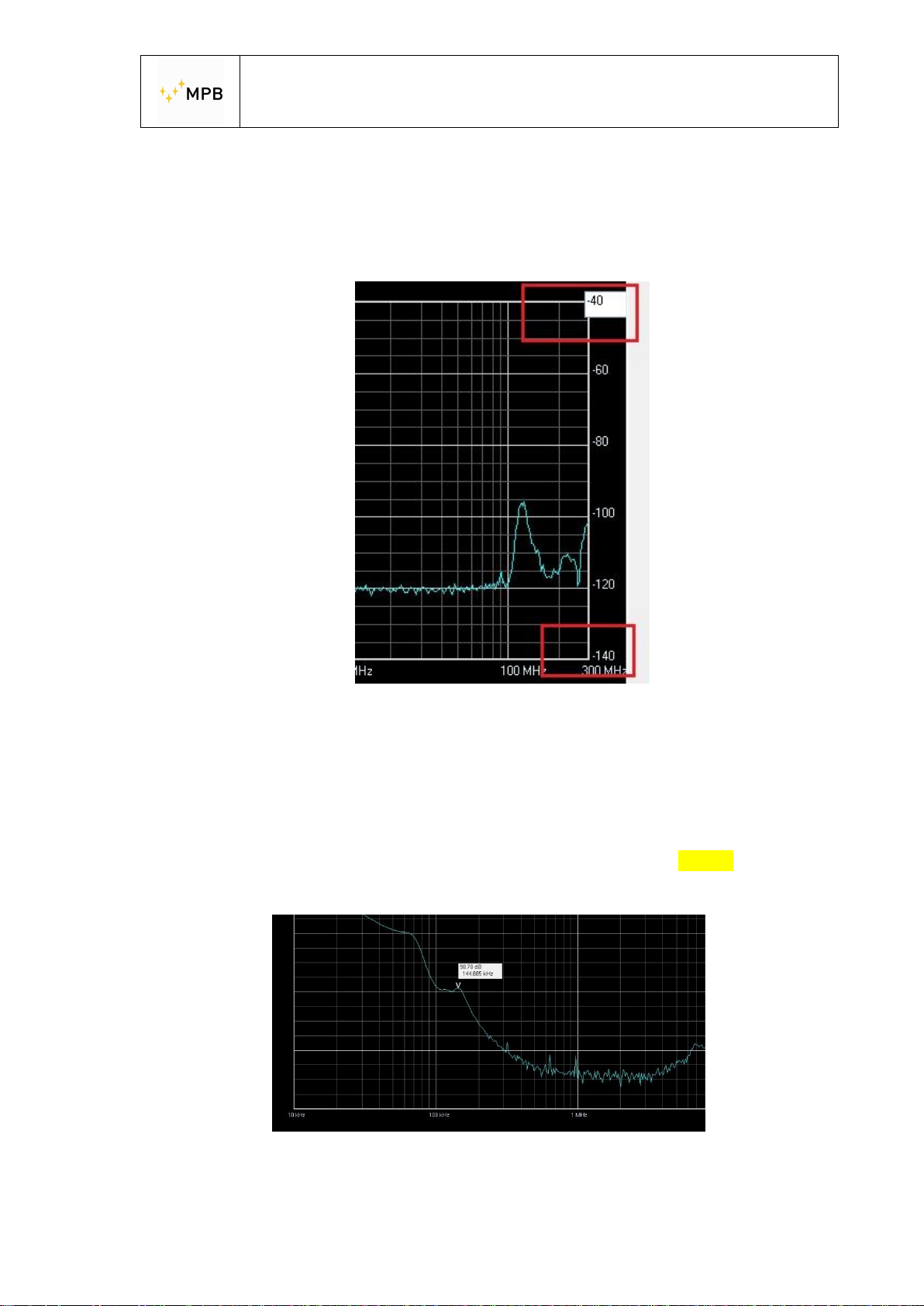
· The color of the graphic can be changed from Options -> Graphic Color.
· The axis reference can be modified by double clicking the maximum and
minimum value of the axis and inserting the desired value.
· You can change the diagram data from Attenuation to Shielding
Effectiveness from Options -> Diagram Style
· Using the File menu you can save or load a record file, or export data in
CSV\ASCII format.
· By clicking any point in the graph you can place a marker showing the
attenuation of the closest measurement point (if the box is Yellow the
measurement point is below the instrument dynamic range)
- 57 -
Page 58
Firmware upgrade
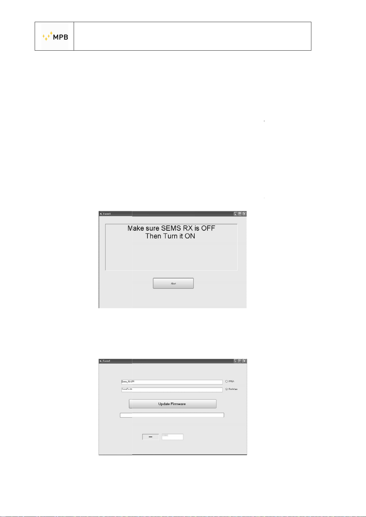
Both the transmitter and the receiver firmware can be updated in the same way.
Be sure that the firmware files are located in the SEMS Software folder.
batteries and connect it to
, run the SEMS
To verify the assignation of the COM port assigned by the PC check in the control
panel, System, Hardware, peripheral, ports
To start the firmware update procedure, click the “Tools” but
and then Update Rx or Update Tx
Supposing you are updating the Rx unit, t
Turn off the receiver and then turn it on again.
how the upgrade window:
the PC using RS232 cable.
oftware and set the COM port in the Option menu
ton , Update Firmware,
will appear:
4.6.
Recharge the unit
Turn on the unit
pressing Select Comm.
S
USER’S MANUAL
S E M S
.
.
he following screen
It will s
- 58 -
Page 59

USER’S MANUAL
S E M S
The updatable file (SemsFw.ldr) should be located in the SEMS software directory.
Press the “Update Firmware” button and wait for the loading.
When the upgrade is completed, close the window and turn off the receiver.
Other information: www.gruppompb.com
Technical information: [email protected]
Phone +39 06 41200744
- 59 -
 Loading...