


MPB S.r.l.
Tel +39 0641200744
Via Giacomo Peroni 400/402 Fax +39 0641200653
00131 ROMA (RM) info@gruppompb.com
www.gruppompb.com
User Manual
CCM
Contact Current
Meter
Updated to Firmware Version:
CCM V1.06
Manual Version:
V1.14

SAFETY NOTES
Read carefully before using the product
MPB works to provide its customers with the best safety conditions available,
complying with the current safety standards. The instrumentation described in
this manual has been produced and tested in conditions that fully comply with
the European standards. To maintain it in safe conditions, ensure the correct use
of the product and prevent any danger, these general instructions must be fully
understood and applied before any use.
This product is intended for industrial environments and laboratories and
should be used by authorized personnel only. The CCM was designed and devel-
oped to be used according to the norms and regulations of the country where the
worker is operating in.
Please use the device only after checking the presence and valid-
ity of the safety devices (e.g. breakers, dierential switches and the
conformity of the grounding)
MPB disclaims any responsibility for a dierent use of the device.
For safety reasons, the
GROUND PLANE
mode measurement (whose expla-
nation will be detailed in the following chapters) MUST always be done
before
the
HAND
mode measurement. The
GROUND PLANE
mode measurement
shall not exceed the limits dened by the 2013/35/EU regulation (CCM-A ver-
sion) or 2004/40/EC (for the CCM version) and must be performed ONLY with
the cover provided with the instrument. Please also note that even when in
GROUND PLANE
mode, total safety is not guaranteed if the use of the instru-
ment is not made according to the instructions explained in this manual. All
these procedures will be better underlined below.
II - USER MANUAL-V1_14 CCM EN
Declaration of Conformity
(in accordance with the Directives: EMC 89/336/EEC and Low Voltage 73/23/EEC)
This is to certify that the product: CCM
(Contact Current Meter)
complies with the following European Standards:
Safety: CEI EN 61010-1 (undated reference, applies to all editions)
EMC: EN 61326-1 (undated reference, applies to all editions)
This product complies with the essential requirements of the Low Voltage Directive
2014/35/EU, EMC directive 2014/30/EU and with the RoHs Directive 2011/65/EU.
MPB S.r.l.
USER MANUAL-V1_14 CCM EN - III
IV - USER MANUAL-V1_14 CCM EN

Contents
1 General Information 1
1.1 Introduction . . . . . . . . . . . . . . . . . . . . . . . . . . . . . . 2
1.2 Description . . . . . . . . . . . . . . . . . . . . . . . . . . . . . . 2
1.3 Composition . . . . . . . . . . . . . . . . . . . . . . . . . . . . . . 2
1.3.1 Standard Conguration . . . . . . . . . . . . . . . . . . . . 2
1.3.2 Optional Kit . . . . . . . . . . . . . . . . . . . . . . . . . . 3
1.3.3 Optional Item . . . . . . . . . . . . . . . . . . . . . . . . . 3
1.4 Front . . . . . . . . . . . . . . . . . . . . . . . . . . . . . . . . . . 4
1.5 Rear . . . . . . . . . . . . . . . . . . . . . . . . . . . . . . . . . . 5
1.6 Technical Specications . . . . . . . . . . . . . . . . . . . . . . . . 6
2 Principle of operation 9
2.1 Logic Schema . . . . . . . . . . . . . . . . . . . . . . . . . . . . . 9
2.2 Measurements . . . . . . . . . . . . . . . . . . . . . . . . . . . . . 10
2.3 Contact Current . . . . . . . . . . . . . . . . . . . . . . . . . . . . 10
2.4 Safety . . . . . . . . . . . . . . . . . . . . . . . . . . . . . . . . . 11
3 CCM Usage 13
3.1 Turn On . . . . . . . . . . . . . . . . . . . . . . . . . . . . . . . . 13
3.2 First Use . . . . . . . . . . . . . . . . . . . . . . . . . . . . . . . . 14
3.3 Standby Screen . . . . . . . . . . . . . . . . . . . . . . . . . . . . 16
3.4 Hand or GP . . . . . . . . . . . . . . . . . . . . . . . . . . . . . . 16
3.5 Bandwidth/Total . . . . . . . . . . . . . . . . . . . . . . . . . . . 18
3.6 Built-in self-test . . . . . . . . . . . . . . . . . . . . . . . . . . . . 19
3.7 CCM Menu . . . . . . . . . . . . . . . . . . . . . . . . . . . . . . 21
3.7.1 Regulation limits . . . . . . . . . . . . . . . . . . . . . . . 22
3.7.2 Beep on press . . . . . . . . . . . . . . . . . . . . . . . . . 22
3.7.3 Alarm . . . . . . . . . . . . . . . . . . . . . . . . . . . . . 22
3.7.4 Auto OFF . . . . . . . . . . . . . . . . . . . . . . . . . . . 23
3.7.5 Date & Time . . . . . . . . . . . . . . . . . . . . . . . . . 24
3.7.6 Contrast . . . . . . . . . . . . . . . . . . . . . . . . . . . . 25
3.7.7 Clear Data . . . . . . . . . . . . . . . . . . . . . . . . . . . 25
V

CONTENTS
4 Data Download 27
4.1 Connect to PC . . . . . . . . . . . . . . . . . . . . . . . . . . . . 27
4.2 Data Format . . . . . . . . . . . . . . . . . . . . . . . . . . . . . 28
5 JIG - General Information 31
5.1 Introduction . . . . . . . . . . . . . . . . . . . . . . . . . . . . . . 31
5.2 Description . . . . . . . . . . . . . . . . . . . . . . . . . . . . . . 32
5.3 Composition . . . . . . . . . . . . . . . . . . . . . . . . . . . . . . 32
5.4 Kit Case . . . . . . . . . . . . . . . . . . . . . . . . . . . . . . . . 33
6 JIG - Functioning 35
6.1 Equipment . . . . . . . . . . . . . . . . . . . . . . . . . . . . . . . 35
6.2 Install the CCM on the JIG . . . . . . . . . . . . . . . . . . . . . 36
6.3 Ground Plane Test . . . . . . . . . . . . . . . . . . . . . . . . . 38
6.4 Hand Test . . . . . . . . . . . . . . . . . . . . . . . . . . . . . . 39
6.5 Certicate Measurements . . . . . . . . . . . . . . . . . . . . . . . 40
6.5.1 Low Band . . . . . . . . . . . . . . . . . . . . . . . . . . . 40
6.5.2 Medium Band . . . . . . . . . . . . . . . . . . . . . . . . . 40
6.5.3 High Band . . . . . . . . . . . . . . . . . . . . . . . . . . . 41
Figures List 44
VI - USER MANUAL-V1_14 CCM EN
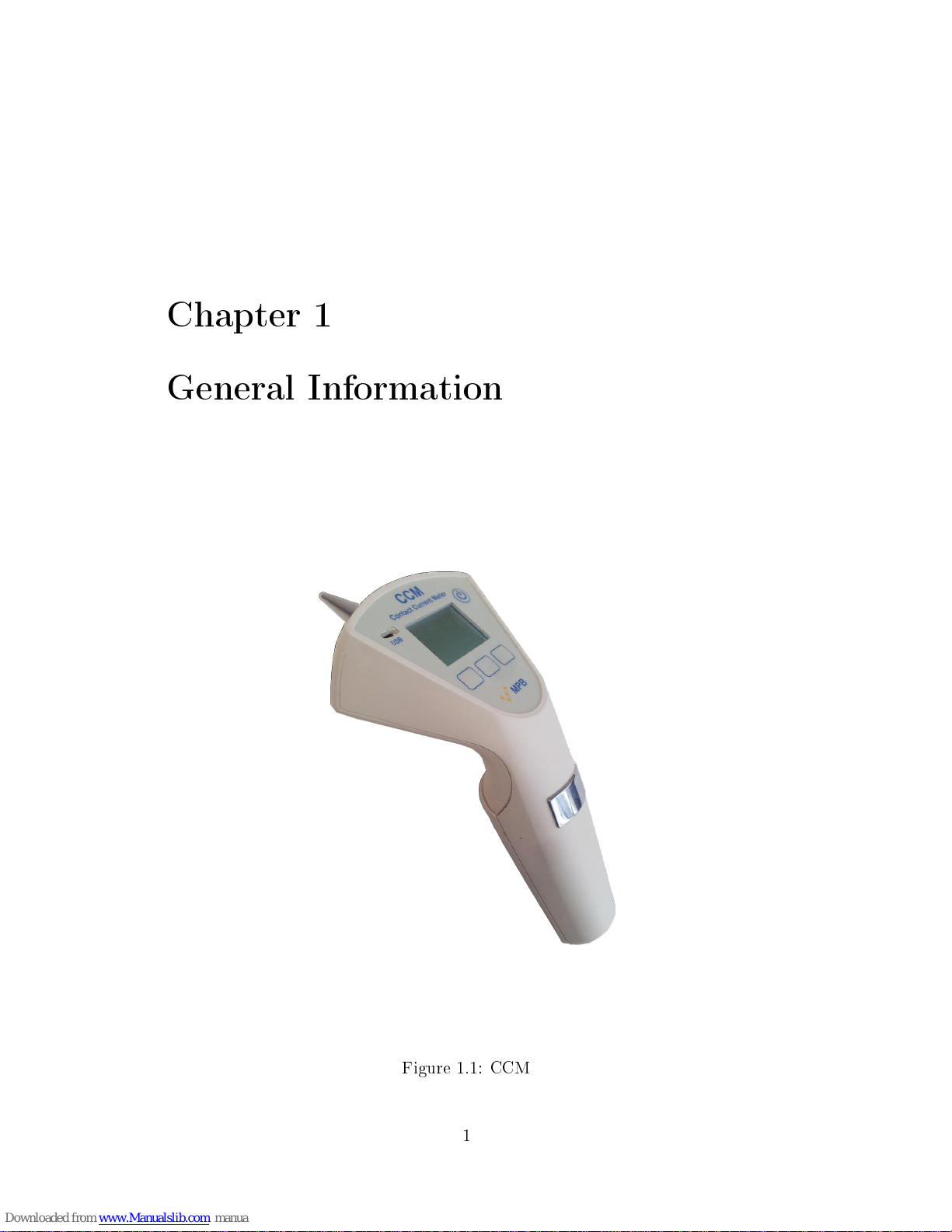
Chapter 1
General Information
Figure 1.1: CCM
1
1. General Information
1.1 Introduction
CCM was designed to measure in a fast and accurate way the contact current
that may be generated when touching electrical/electronic equipment inside a
radio frequency eld.
1.2 Description
CCM (Figure 1.1) is a portable measuring device with two measurement modes.
It can measure by means of the
GROUND PLANE
(with related cover to wrap
the instrument and resistance for closing the circuit on the ground), and it can
work without a cable, making use of the impedance level of the user through the
conductive area on the handle. In the next chapters we will go more deeply into
this subject.
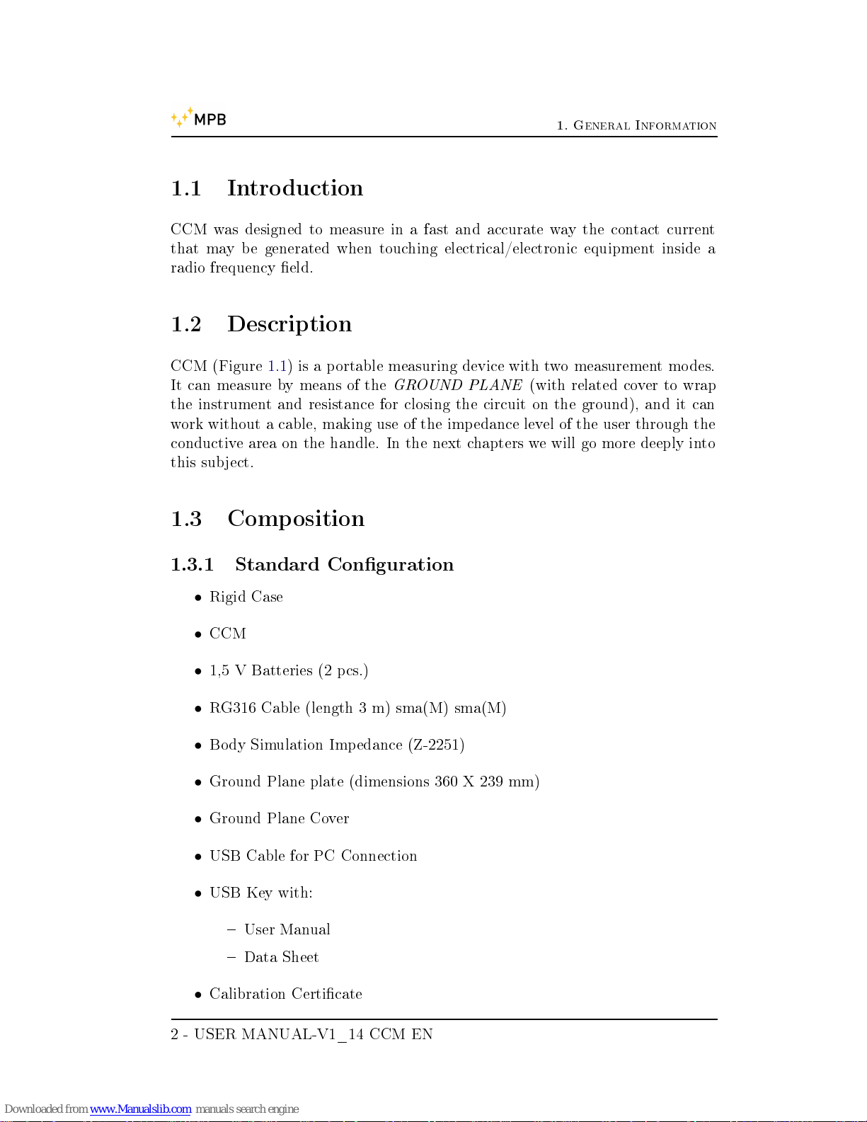
1.3 Composition
1.3.1 Standard Conguration
•
Rigid Case
•
CCM
•
1,5 V Batteries (2 pcs.)
•
RG316 Cable (length 3 m) sma(M) sma(M)
•
Body Simulation Impedance (Z-2251)
•
Ground Plane plate (dimensions 360 X 239 mm)
•
Ground Plane Cover
•
USB Cable for PC Connection
•
USB Key with:
User Manual
Data Sheet
•
Calibration Certicate
2 - USER MANUAL-V1_14 CCM EN

1. General Information
1.3.2 Optional Kit
CCM-JIG Kit, including:
•
Calibration JIG
•
Standard resistance (R45)
•
Cable (length 1 m) N(M) sma(M)
1.3.3 Optional Item
•
IEC-60990 Body Simulation Impedance
USER MANUAL-V1_14 CCM EN - 3

1. General Information
1.4 Front
In Figure 1.2 is shown the CCM front panel:
On/O switch
Micro USB connector
Keyboard
Figure 1.2: CCM front
4 - USER MANUAL-V1_14 CCM EN
1. General Information
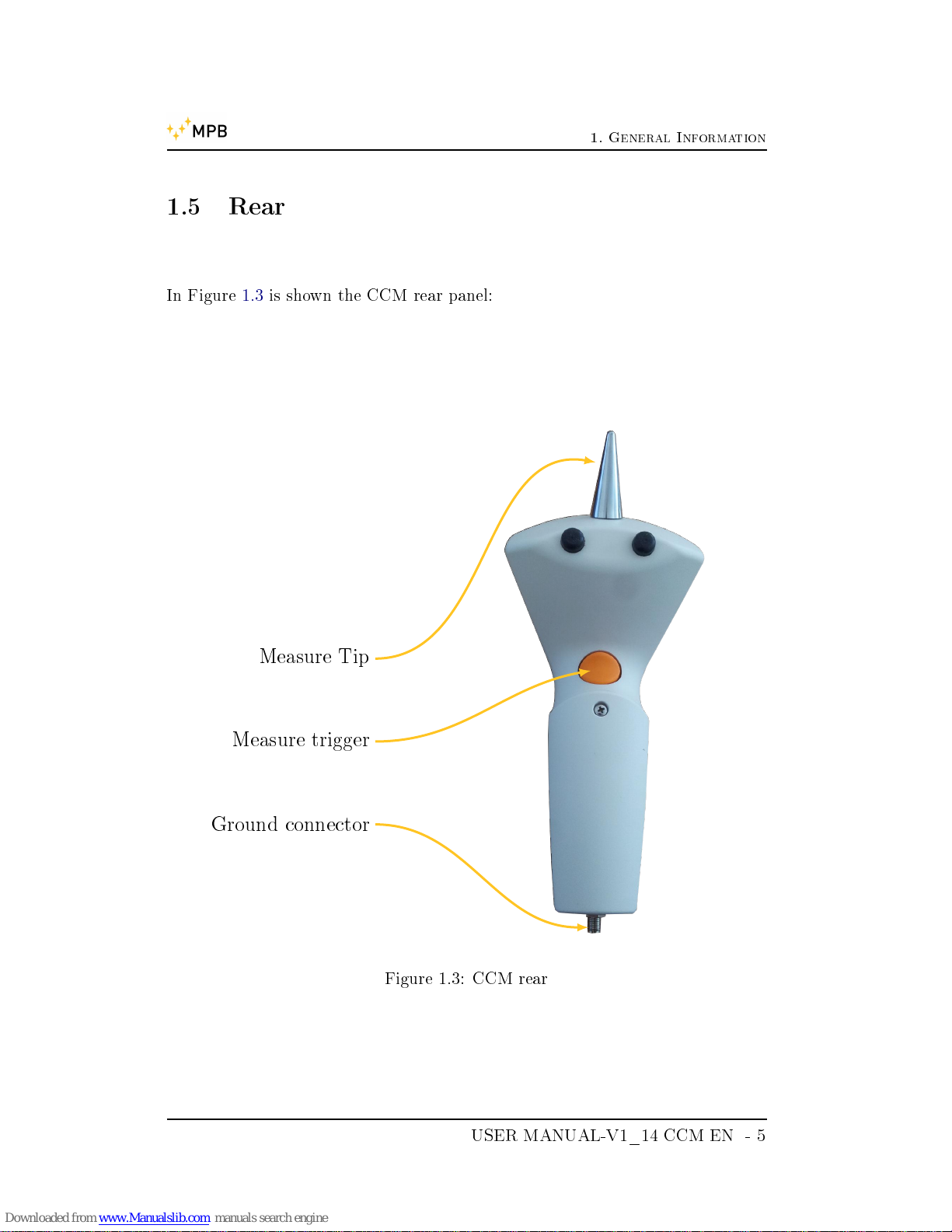
1.5 Rear
In Figure 1.3 is shown the CCM rear panel:
Measure Tip
Measure trigger
Ground connector
Figure 1.3: CCM rear
USER MANUAL-V1_14 CCM EN - 5
1. General Information
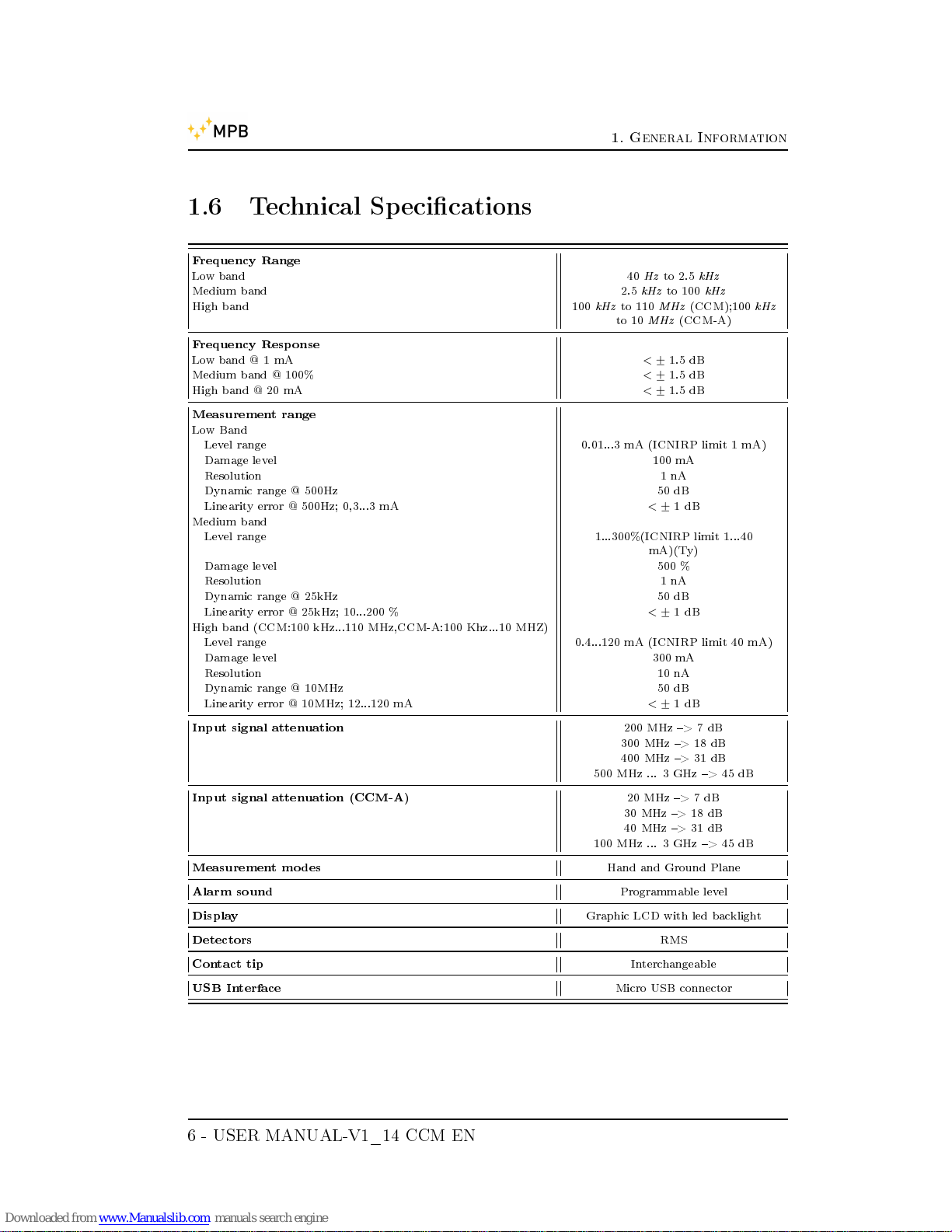
1.6 Technical Specications
Frequency Range
Low band 40Hzto 2.5
kHz
Medium band 2.5
kHz
to 100
kHz
High band 100
kHz
to 110
MHz
(CCM);100
kHz
to 10
MHz
(CCM-A)
Frequency Response
Low band @ 1 mA
<
+
−
1.5 dB
Medium band @ 100%
<
+
−
1.5 dB
High band @ 20 mA
<
+
−
1.5 dB
Measurement range
Low Band
Level range 0.01...3 mA (ICNIRP limit 1 mA)
Damage level 100 mA
Resolution 1 nA
Dynamic range @ 500Hz 50 dB
Linearity error @ 500Hz; 0,3...3 mA
<
+
−
1 dB
Medium band
Level range 1...300%(ICNIRP limit 1...40
mA)(Ty)
Damage level 500 %
Resolution 1 nA
Dynamic range @ 25kHz 50 dB
Linearity error @ 25kHz; 10...200 %
<
+
−
1 dB
High band (CCM:100 kHz...110 MHz,CCM-A:100 Khz...10 MHZ)
Level range 0.4...120 mA (ICNIRP limit 40 mA)
Damage level 300 mA
Resolution 10 nA
Dynamic range @ 10MHz 50 dB
Linearity error @ 10MHz; 12...120 mA
<
+
−
1 dB
Input signal attenuation
200 MHz > 7 dB
300 MHz > 18 dB
400 MHz > 31 dB
500 MHz ... 3 GHz > 45 dB
Input signal attenuation (CCM-A)
20 MHz > 7 dB
30 MHz > 18 dB
40 MHz > 31 dB
100 MHz ... 3 GHz > 45 dB
Measurement modes
Hand and Ground Plane
Alarm sound
Programmable level
Display
Graphic LCD with led backlight
Detectors
RMS
Contact tip
Interchangeable
USB Interface
Micro USB connector
6 - USER MANUAL-V1_14 CCM EN
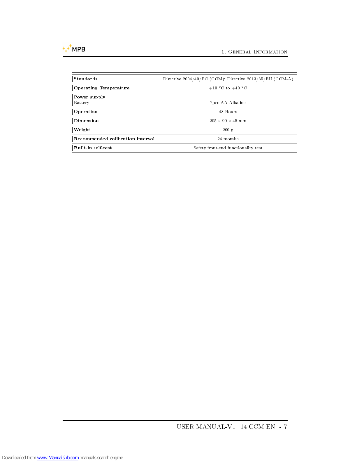
1. General Information
Standards
Directive 2004/40/EC (CCM); Directive 2013/35/EU (CCM-A)
Operating Temperature
+10◦C to +40◦C
Power supply
Battery 2pcs AA Alkaline
Operation
48 Hours
Dimension
205 × 90 × 45
mm
Weight
200 g
Recommended calibration interval
24 months
Built-in self-test
Safety front-end functionality test
USER MANUAL-V1_14 CCM EN - 7
1. General Information
8 - USER MANUAL-V1_14 CCM EN
Chapter 2
Principle of operation
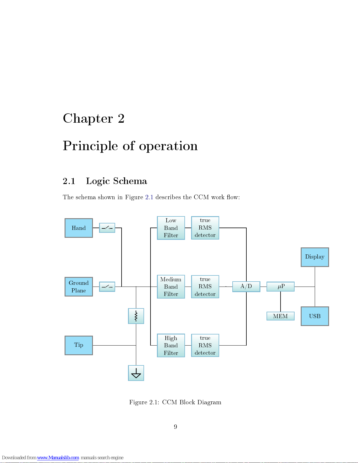
2.1 Logic Schema
The schema shown in Figure 2.1 describes the CCM work ow:
Hand
Low
Band
Filter
true
RMS
detector
Display
Ground
Plane
Medium
Band
Filter
true
RMS
detector
A/D
µ
P
MEM USB
Tip
High
Band
Filter
true
RMS
detector
Figure 2.1: CCM Block Diagram
9

2. Principle of operation
2.2 Measurements
The CCM digital nature allows it to measure contact currents through the true
RMS (Root Mean Square) value for all analog signals from 40Hz. The RMS value
of a waveform signal is equal to a DC current which provides the same power to
the load. The signal measured by the TIP passes through the most suitable lter
(Low, Medium and High), then arrives to the true RMS detector, that makes a
conversion of the measured current to RMS . The equation is the following:
e
rms
=
s
1
T
Z
T
0
V(t)2dt
The actual regulations denes the minimum requirements for the safety of
workers in areas of risk, and the limit values for the exposure to contact current.
2.3 Contact Current
The contact current ows when a person or an object serve as electrical conductors
when reaching another metallic object immersed in an electromagnetic eld: the
contact current is expressed in Amperes. The moment right after the contact can
imply a discharge of associated currents (First attachment of 2013/35/EU). In
the workplace, as well as in the world we live in, the electric and magnetic elds
are always present and can have natural or articial origin. The natural electric
elds are, for example, those produced by the accumulation of electric charges
during a lightning, while the natural magnetic elds are those that are found in
nature, such as the terrestrial one that orients the compass needle North-South.
The electric and magnetic articial elds are produced by articial devices and
systems, such as electrical equipment or systems for the distribution of electricity.
The electromagnetic eld can be dened as a physical phenomenon resulting
from the simultaneous presence of an electric eld and a magnetic eld. Moving
from the source of the electromagnetic eld, the waves decrease in intensity,
it is therefore clear that the intensity is maximum if there is a contact with
the object or with the system which is generating the electromagnetic eld. A
device with metallic shell, if immersed in an electromagnetic eld, can become
a RF voltage carrier and can accumulate electrical charges. If you come into
contact with the device without adequate protection, you can risk that the RF
voltage discharges to ground owing through the limbs and the body. In this
case, the electrical charges on the device, immersed in the electric eld through
the operator's body, have generated a contact current. An electrical equipment
not properly shielded can emit electromagnetic waves. When coming into contact
with that machinery without adequate protection, even in this case there is a risk
that the electromagnetic waves, owing through the limbs and the operator's
body, can generate a contact current.
10 - USER MANUAL-V1_14 CCM EN

2. Principle of operation
2.4 Safety
The GP measurement mode has only been developed for safety reasons, since it
does not guarantee reliable measurements. For the operator's safety and security
it is absolutely mandatory to make sure that, when performing GP measurements,
the cover provided with the instruments wraps it like in the picture below, the
plate is set in the same position as the operator's and the impedance is connected
to the plate connector and not to the CCM. For more details please scroll down
to 3.4
;
Figure 2.2: GP cover
USER MANUAL-V1_14 CCM EN - 11

2. Principle of operation
12 - USER MANUAL-V1_14 CCM EN

Chapter 3
CCM Usage
3.1 Turn On
Release n
◦
Figure 3.1: Turned On CCM
When the CCM is on, it displays the MPB logo and the rmware version
(Figure 3.1). After a few seconds a warning message will appear (as in Figure 3.2),
and users have to declare to have read this manual and to be aware of the risks
involved during the current measurement. In case of negative answer (by pressing
DENY), the device will automatically turn o.
13
3. CCM Usage
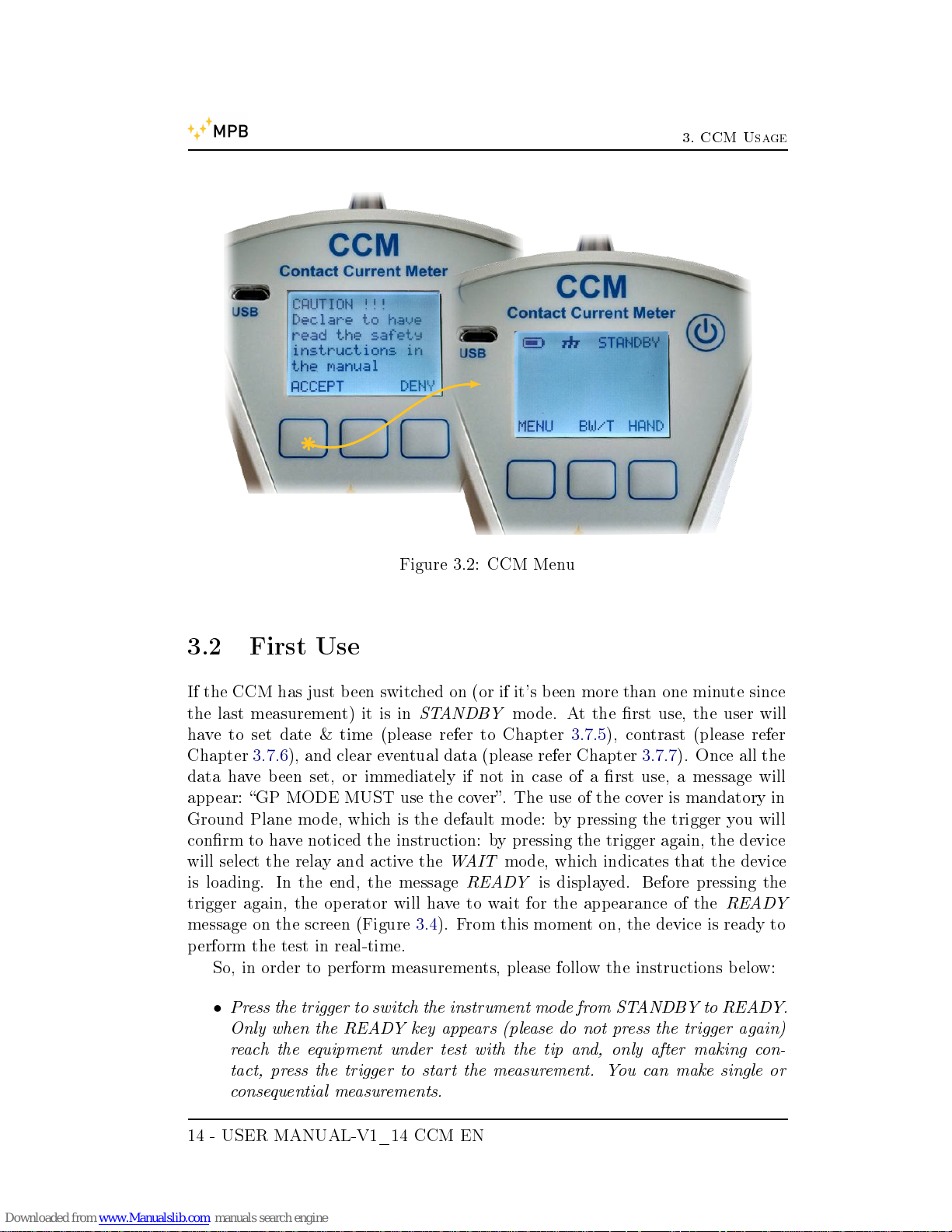
Figure 3.2: CCM Menu
3.2 First Use
If the CCM has just been switched on (or if it's been more than one minute since
the last measurement) it is in
STANDBY
mode. At the rst use, the user will
have to set date & time (please refer to Chapter 3.7.5), contrast (please refer
Chapter 3.7.6), and clear eventual data (please refer Chapter 3.7.7). Once all the
data have been set, or immediately if not in case of a rst use, a message will
appear: GP MODE MUST use the cover. The use of the cover is mandatory in
Ground Plane mode, which is the default mode: by pressing the trigger you will
conrm to have noticed the instruction: by pressing the trigger again, the device
will select the relay and active the
WAIT
mode, which indicates that the device
is loading. In the end, the message
READY
is displayed. Before pressing the
trigger again, the operator will have to wait for the appearance of the
READY
message on the screen (Figure 3.4). From this moment on, the device is ready to
perform the test in real-time.
So, in order to perform measurements, please follow the instructions below:
•
Press the trigger to switch the instrument mode from STANDBY to READY.
Only when the READY key appears (please do not press the trigger again)
reach the equipment under test with the tip and, only after making con-
tact, press the trigger to start the measurement. You can make single or
consequential measurements.
14 - USER MANUAL-V1_14 CCM EN

3. CCM Usage
Figure 3.3: GP cover message
Figure 3.4: Ready for measuring
•
With each new measurement, the operator will be warned by an acoustic
signal (if enabled) and, simultaneously, by a brighter display illumination.
All measures are automatically stored by the CCM.
•
In both modes the measuring tip of the CCM must never be removed from
the equipment under test.
USER MANUAL-V1_14 CCM EN - 15

3. CCM Usage
3.3 Standby Screen
In Figure 3.5 is shown the standby screen. On the top part, you will nd:
State
Measurement Mode
Battery level
Figure 3.5: First Use
•
Battery
indicator.
•
The
Measurement Mode
icon shows which kind of circuit is selected in that
specic measurement session, and (we'll see that more accurately in next
paragraph) there are two dierent measurement modes:
HAND
for measurements that use the body impedance of the operator as a
reference.
GP
(or
GROUND PLANE
) for measurements that concern the supplied
metal plate with a standardized impedance as a reference.
•
The
State
indicates to the user whether the device is ready to make a
measurement or not.
3.4 Hand or GP
Please remember that the GP measurement mode does not guarantee reliable
measurements but it must be in any case performed before the Hand measurement
16 - USER MANUAL-V1_14 CCM EN

3. CCM Usage
mode due to safety reasons, and with the cover provided in the case wrapping
the instrument. Please scroll back to 2.4 for more details.
In the main screen, the key on the right (in this specic case it can be
GP
or
HAND
) allows the user to choose which circuit to use for the measurement
(Figure 3.6). It is mandatory to measure with the Ground Plane
before
doing
the
HAND
measurement (so that, in extreme cases, a high current will simply
discharge on the ground). In the
Hand
measurement mode the CCM will instead
consider the real impedance value of the human body.
Figure 3.6: Hand or GP
USER MANUAL-V1_14 CCM EN - 17

3. CCM Usage
3.5 Bandwidth/Total
The central key,
BW/T
, allows the user to choose the visualization mode:
BANDWIDTH Display of the measurement divided by bands (or selective measurement),
with the nal result expressed in mA.
TOTAL Overall view of the measured value, in percentage, compared to the ICNIRP
limit.
%T OT AL = M AX (%LF ; %M F ; %HF )
You can nd below the formulas for LF, MF and HF
Figure 3.7: BW/T
%LF (t) =
valLF
[mA]
(t)
1
[mA]
× 100
%MF (t) =
valM F
[mA]
(t)
0, 4
[
mA
kHz
]
× f
kH z
× 100
%HF (t) =
valH F
[mA]
(t)
40
[mA]
× 100
18 - USER MANUAL-V1_14 CCM EN

3. CCM Usage
You can nd an example of what happens in Figure 3.7. The
Low band Filter
starts at 40 Hz to 2.5 kHz (IC bound = 1 mA), while the
High band Filter
starts
at 0.1 MHz to 110 MHz (10 MHz for the CCM-A version) (IC bound = 40 mA).
The value of the contact current in the range of frequencies ranging from 2.5 kHz
to 100 kHz is displayed when the values of LF and HF are low. For this reason
it is suggested to make the measurement while displaying TOTAL and then
check in BANDWIDTH at what frequency the limit has been exceeded. Please
consider that by the "TOTAL" wording it is not meant that a total summation
is made over all three bands but the Max value from the three bands is taken.
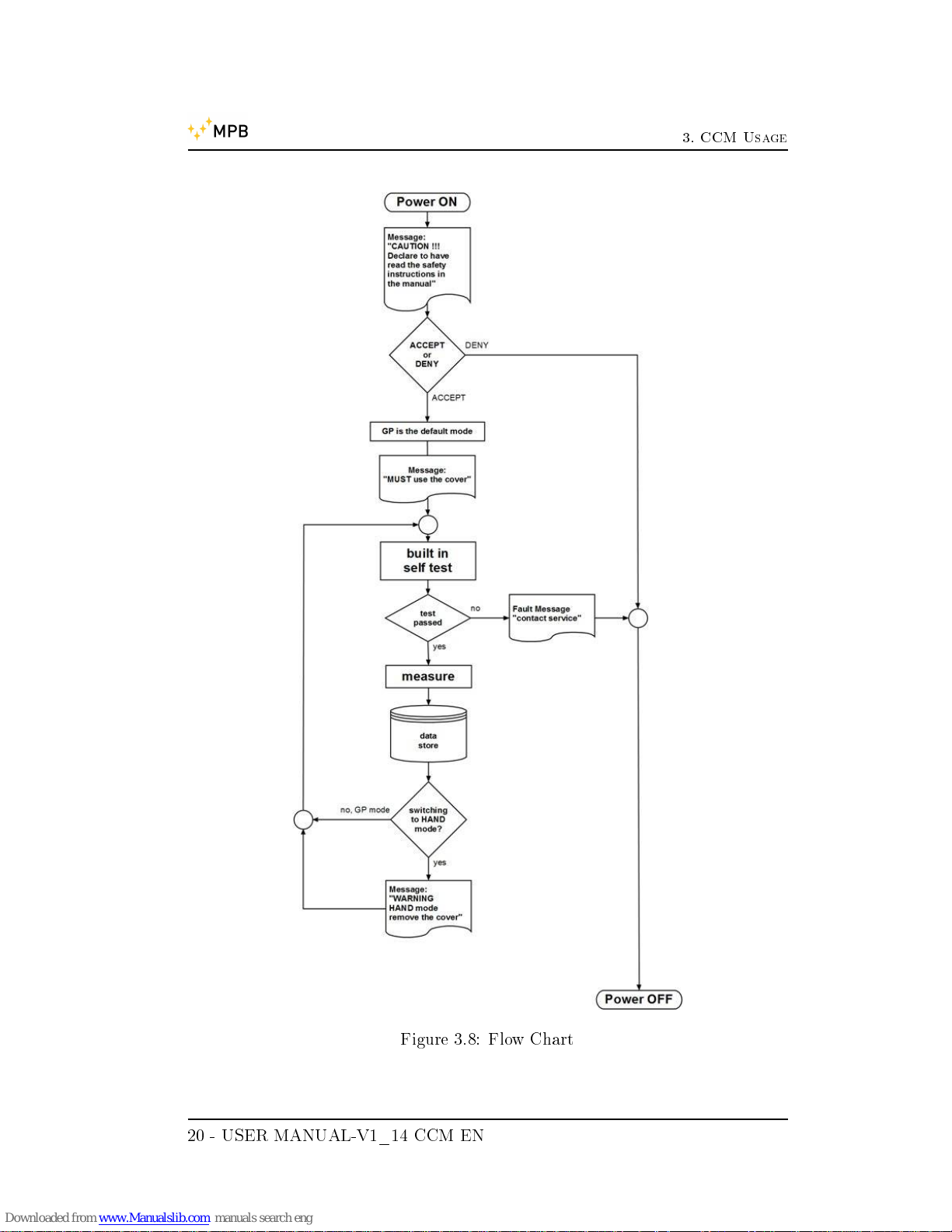
3.6 Built-in self-test
Before any rst Ground Plane measurement, before switching from Ground Plane
to Hand mode and vice versa, back from Hand mode to Ground Plane mode, the
CCM will perform a test to verify the front-end functionality of the instrument.
In case the test is not passed a Contact Service fault message will appear.
WARNING: in case of such message the instrument cannot be used and it will
be mandatory to send it back to MPB for a full check. In case the test is passed,
a GP mode measurement (always through the cover provided) will be allowed.
Performed the measurement and stored the data, it will be allowed to switch to
Hand mode, after showing the message warning HAND mode, remove the cover.
Please make sure not to connect to a signal generator the equipment under test
turned o, and then turn it on at a later time: please instead connect it only
after the Ready wording appears
USER MANUAL-V1_14 CCM EN - 19
3. CCM Usage
Figure 3.8: Flow Chart
20 - USER MANUAL-V1_14 CCM EN

3. CCM Usage
Figure 3.9: Built-in Self-test
Figure 3.10: GP-Hand switching
3.7 CCM Menu
The next part of the manual sequentially shows the possible congurations of the
device.
USER MANUAL-V1_14 CCM EN - 21
3. CCM Usage
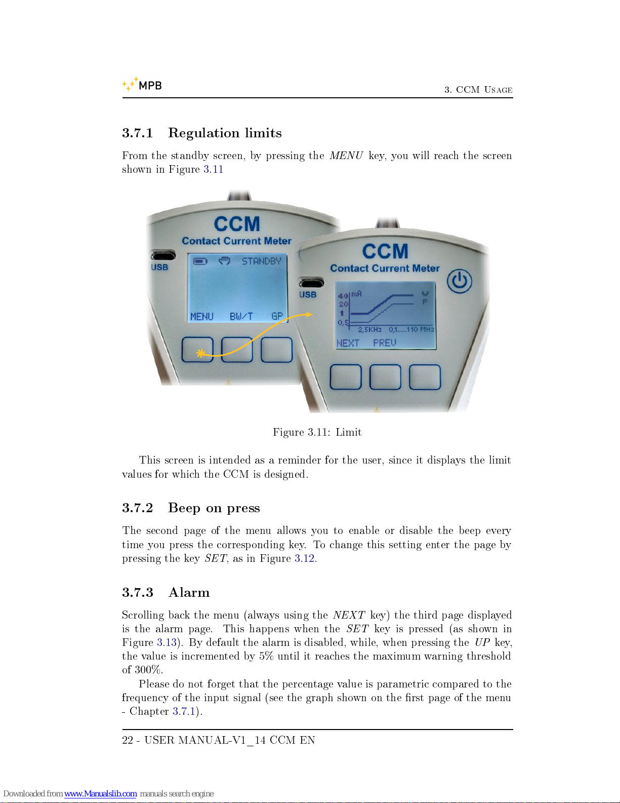
3.7.1 Regulation limits
From the standby screen, by pressing the
MENU
key, you will reach the screen
shown in Figure 3.11
Figure 3.11: Limit
This screen is intended as a reminder for the user, since it displays the limit
values for which the CCM is designed.
3.7.2 Beep on press
The second page of the menu allows you to enable or disable the beep every
time you press the corresponding key. To change this setting enter the page by
pressing the key
SET
, as in Figure 3.12.
3.7.3 Alarm
Scrolling back the menu (always using the
NEXT
key) the third page displayed
is the alarm page. This happens when the
SET
key is pressed (as shown in
Figure 3.13). By default the alarm is disabled, while, when pressing the
UP
key,
the value is incremented by 5% until it reaches the maximum warning threshold
of 300%.
Please do not forget that the percentage value is parametric compared to the
frequency of the input signal (see the graph shown on the rst page of the menu
- Chapter 3.7.1).
22 - USER MANUAL-V1_14 CCM EN

3. CCM Usage
Figure 3.12: Beep on press
Figure 3.13: Alarm
3.7.4 Auto OFF
Through this setting the user can decide how long after inaction it will take before
the device will automatically shutdown. This is the fourth page of the menu, and
in Figure 3.14 you can see how, also on this page, the left and center key change
USER MANUAL-V1_14 CCM EN - 23

3. CCM Usage
usage.
Figure 3.14: Auto O
Ranges for this setting vary from 10 minutes to 60 minutes ( with a 10 minutes
span). You cannot disable this option for battery saving.
3.7.5 Date & Time
The fth menu item allows you to change the date and time of the device (Fig-
ure 3.15). It is important that this information is correct, because the results of
the measurements in the downloaded data (csv le generated by the device) are
associated with the day and time of the measurements.
The changes of the elds are carried out using the keys
UP
and
DOWN
, and
will follow the sequential order of day, month, year, hours, minutes and seconds.
24 - USER MANUAL-V1_14 CCM EN

3. CCM Usage
Figure 3.15: Date & Time
3.7.6 Contrast
The sixth page of the menu (Figure 3.16) allows you to change the contrast of the
LCD display by using the same keys,
UP
and
DOWN
. By default an intermediate
value is already set.
3.7.7 Clear Data
In this menu, the operator has the possibility to delete all the data stored in the
internal memory. If measurements from the previous session have remained, it
is possible to clean the memory without a PC. The Figure 3.17 shows how this
functionality works.
USER MANUAL-V1_14 CCM EN - 25

3. CCM Usage
Figure 3.16: Contrast
Figure 3.17: Clear Data
26 - USER MANUAL-V1_14 CCM EN
Chapter 4
Data Download
4.1 Connect to PC
The data downloading operation has been designed to improve the speed and
simplicity of use. The data generated by the CCM are stored in
csv
(comma
separated value), which is a text le with value separators. This allows the user
to read, edit and process the downloaded data via various software including
MS
Excel
.
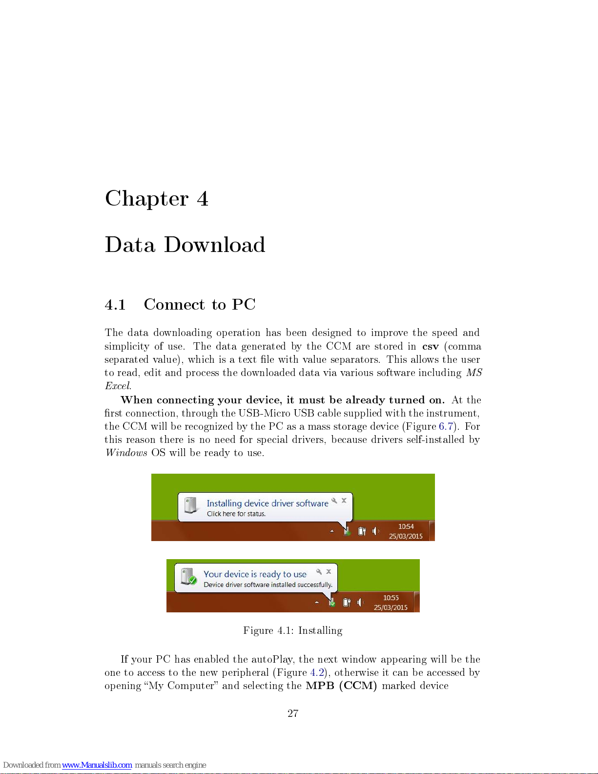
When connecting your device, it must be already turned on.
At the
rst connection, through the USB-Micro USB cable supplied with the instrument,
the CCM will be recognized by the PC as a mass storage device (Figure 6.7). For
this reason there is no need for special drivers, because drivers self-installed by
Windows
OS will be ready to use.
Figure 4.1: Installing
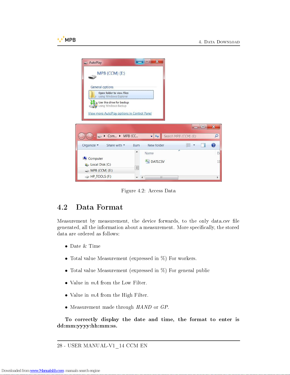
If your PC has enabled the autoPlay, the next window appearing will be the
one to access to the new peripheral (Figure 4.2), otherwise it can be accessed by
opening My Computer and selecting the
MPB (CCM)
marked device
27
4. Data Download
Figure 4.2: Access Data
4.2 Data Format
Measurement by measurement, the device forwards, to the only data.csv le
generated, all the information about a measurement. More specically, the stored
data are ordered as follows:
•
Date & Time
•
Total value Measurement (expressed in %) For workers.
•
Total value Measurement (expressed in %) For general public
•
Value in
mA
from the Low Filter.
•
Value in
mA
from the High Filter.
•
Measurement made through
HANDorGP
.
To correctly display the date and time, the format to enter is
dd:mm:yyyy:hh:mm:ss.
28 - USER MANUAL-V1_14 CCM EN

4. Data Download
To correctly display the acquired values: the decimal separator is
the . (point), and the digit grouping symbol is a , (comma)
In case of visualization issues, please change the Language and re-
gion setting in the control panel
This le, opened with
MS Excel
will appear as in Figure 4.3
Figure 4.3: Data dump
USER MANUAL-V1_14 CCM EN - 29

4. Data Download
30 - USER MANUAL-V1_14 CCM EN
Chapter 5
JIG - General Information
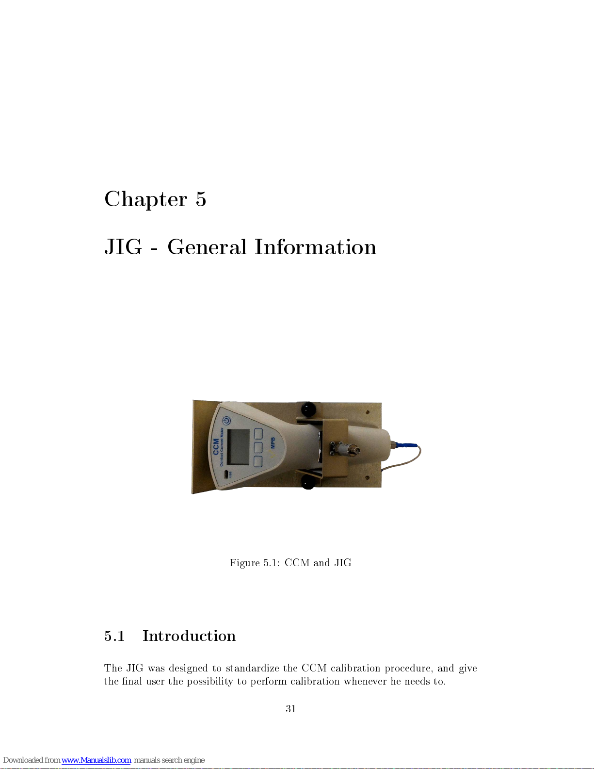
Figure 5.1: CCM and JIG
5.1 Introduction
The JIG was designed to standardize the CCM calibration procedure, and give
the nal user the possibility to perform calibration whenever he needs to.
31

5. JIG - General Information
5.2 Description
The JIG is built on an iron base, with a connector to be plugged to the CCM's
Jig room, an iron locking stirrup designed for the HAND plate, and adaptive
connectors designed for the contact current meter. This guarantees a stable
support during the test procedure. During that, the user will have to subject the
device to RF signals, using the special connectors on the JIG or on the CCM
itself.
5.3 Composition
The CCM with the JIG option comes with:
•
Rigid Case
•
CCM
•
1,5 V batteries (2 pcs)
•
RG316 Cable (length 3 m) sma(M) sma(M)
•
Body Simulation Impedance (Z-2251)
•
Ground Plane Plate (dimensions 360 x 239 mm)
•
Ground Plane cover
•
USB Key with:
User Manual
Data Sheet
•
Calibration Certicate
•
Calibration JIG
•
Standard resistance (R45)
•
Cable (length 1 m) N(M)-sma (M)
32 - USER MANUAL-V1_14 CCM EN

5. JIG - General Information
5.4 Kit Case
In Figure 5.2 is shown the complete Kit for the CCM:
GP Compartment
CCM
JIG lock
JIG
R45 and Z-2251
Batteries
Figure 5.2: Case
USER MANUAL-V1_14 CCM EN - 33

5. JIG - General Information
In Figure 5.3 is shown the inner compartment of the case:
Ground Plane
Thickness
Figure 5.3: Case Compartment
34 - USER MANUAL-V1_14 CCM EN

Chapter 6
JIG - Functioning
6.1 Equipment
To use the JIG is necessary to have a signal generator, able to generate sinusoidal
signals from 40 Hz to 110 MHz. All the other tools needed for the calibration are
supplied with the JIG kit. For the specic connection with the signal generator,
a N-sma cable (as in Figure 6.1)and a R45 resistance will be used;
6.1.
Figure 6.1: Cable and resistance
The CCM has an inner resistance of 5 Ohm and, since almost all the signal
generators are adapted for 50 Ohm, 45 Ohm must be added to the load. assem-
bling the resistance included on the sma attack of the cable. The connector must
be plugged to the generator. In the next paragraphs, we will see dierent ways
of plugging the CCM through this conguration.
35
6. JIG - Functioning
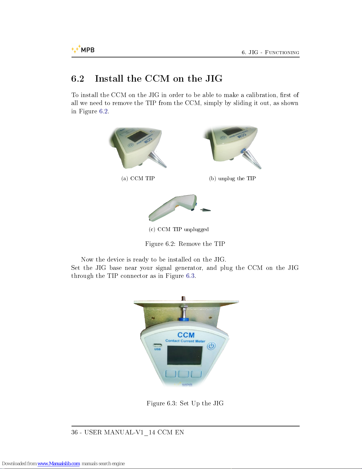
6.2 Install the CCM on the JIG
To install the CCM on the JIG in order to be able to make a calibration, rst of
all we need to remove the TIP from the CCM, simply by sliding it out, as shown
in Figure 6.2.
(a) CCM TIP (b) unplug the TIP
(c) CCM TIP unplugged
Figure 6.2: Remove the TIP
Now the device is ready to be installed on the JIG.
Set the JIG base near your signal generator, and plug the CCM on the JIG
through the TIP connector as in Figure 6.3.
Figure 6.3: Set Up the JIG
36 - USER MANUAL-V1_14 CCM EN

6. JIG - Functioning
The next step is to lock down the CCM with the special JIG lock using the
knobs, so that the HAND plate will be connected to the lock sma connector (the
result is shown in Figure 6.4).
tighten
Figure 6.4: Set Up the JIG
It's important to tighten the knobs on the basis, just to ensure a good con-
ductivity between the metal JIG and its lock plate.
USER MANUAL-V1_14 CCM EN - 37

6. JIG - Functioning
6.3 Ground Plane Test
WARNING: Please do not shift from Hand mode to GP mode (and vice versa) on
the equipment under test, when the equipment is connected to a signal generator.
As already described on the CCM manual, the GROUND PLANE measure
has to be done before the HAND measure. To properly connect the device plane
connector to the generator we will use our N-sma cable and the R45 resistance
as in Figure 6.5.
Figure 6.5: Ground Plane Plug
We can now turn on the device and set up the Ground Plane mode. Once
the signal generator is congured and operating, you can pull the trigger and
perform the measurement.
1. turn on the device under test and wait for the READY wording
2. plug the R45 adapter to the SMA connector in the GP input
3. plug the SMA-N cable to the adapter and to the signal generator
4. set the generator on the appropriate level
5. switch to the GP mode (see Chapter 3.4)
6. press the GET button to perform the measurement
For instructions on how to set the generator please see the examples in 6.5.1,
6.5.2 and 6.5.3.
38 - USER MANUAL-V1_14 CCM EN
6. JIG - Functioning
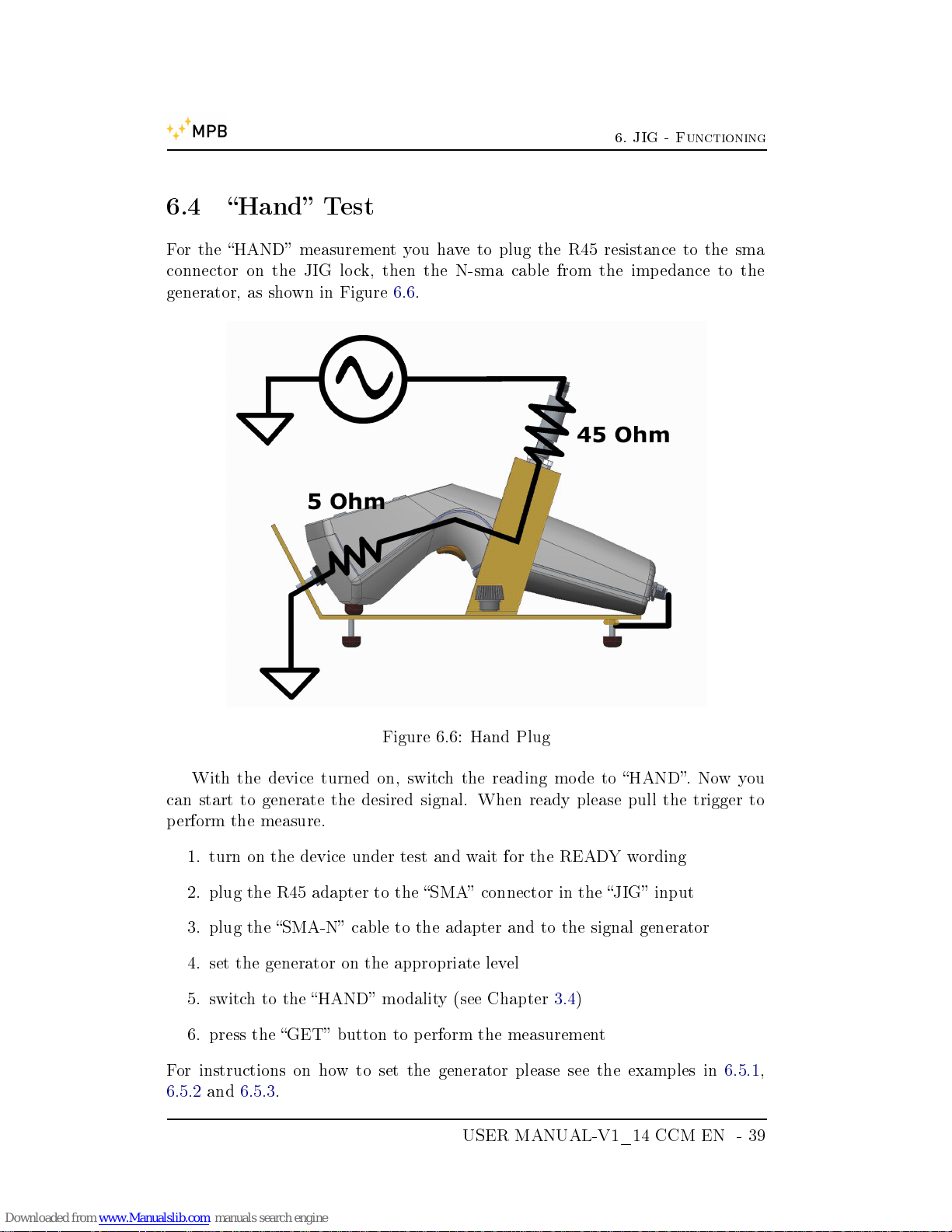
6.4 Hand Test
For the HAND measurement you have to plug the R45 resistance to the sma
connector on the JIG lock, then the N-sma cable from the impedance to the
generator, as shown in Figure 6.6.
Figure 6.6: Hand Plug
With the device turned on, switch the reading mode to HAND. Now you
can start to generate the desired signal. When ready please pull the trigger to
perform the measure.
1. turn on the device under test and wait for the READY wording
2. plug the R45 adapter to the SMA connector in the JIG input
3. plug the SMA-N cable to the adapter and to the signal generator
4. set the generator on the appropriate level
5. switch to the HAND modality (see Chapter 3.4)
6. press the GET button to perform the measurement
For instructions on how to set the generator please see the examples in 6.5.1,
6.5.2 and 6.5.3.
USER MANUAL-V1_14 CCM EN - 39
6. JIG - Functioning
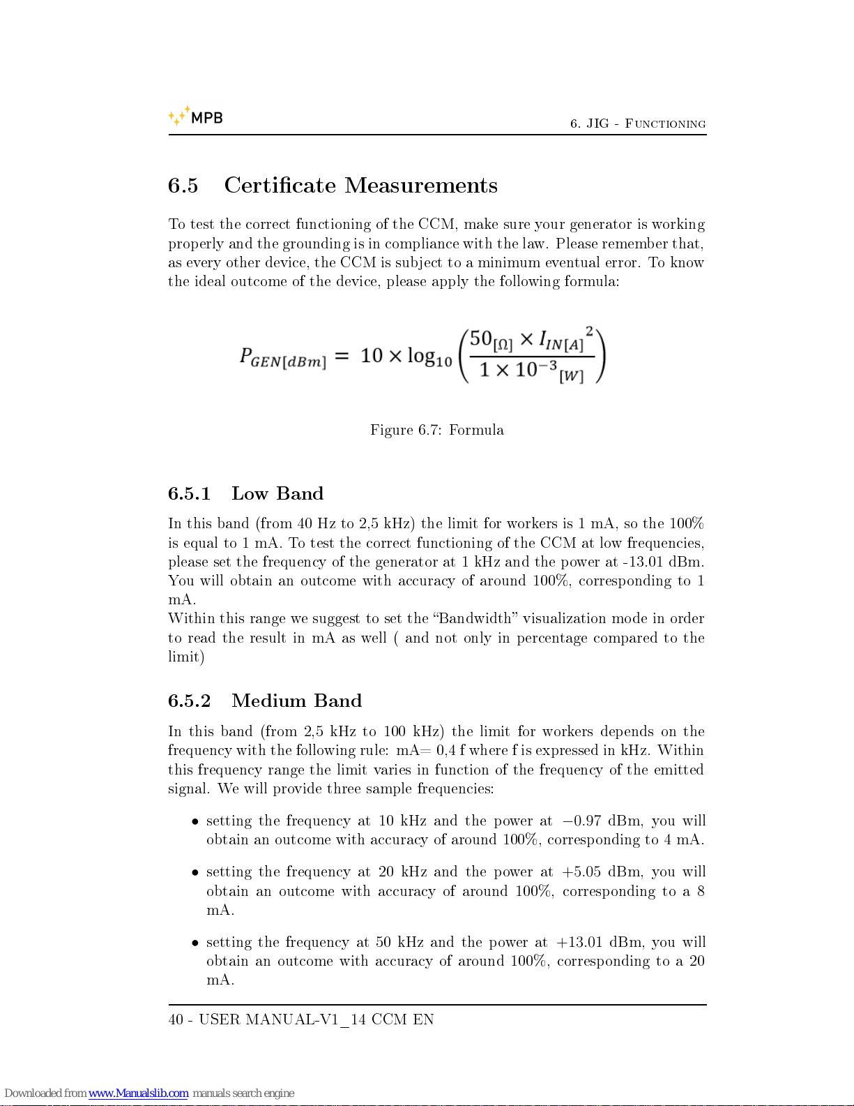
6.5 Certicate Measurements
To test the correct functioning of the CCM, make sure your generator is working
properly and the grounding is in compliance with the law. Please remember that,
as every other device, the CCM is subject to a minimum eventual error. To know
the ideal outcome of the device, please apply the following formula:
Figure 6.7: Formula
6.5.1 Low Band
In this band (from 40 Hz to 2,5 kHz) the limit for workers is 1 mA, so the 100%
is equal to 1 mA. To test the correct functioning of the CCM at low frequencies,
please set the frequency of the generator at 1 kHz and the power at -13.01 dBm.
You will obtain an outcome with accuracy of around 100%, corresponding to 1
mA.
Within this range we suggest to set the Bandwidth visualization mode in order
to read the result in mA as well ( and not only in percentage compared to the
limit)
6.5.2 Medium Band
In this band (from 2,5 kHz to 100 kHz) the limit for workers depends on the
frequency with the following rule: mA= 0,4 f where f is expressed in kHz. Within
this frequency range the limit varies in function of the frequency of the emitted
signal. We will provide three sample frequencies:
•
setting the frequency at 10 kHz and the power at
−0.97
dBm, you will
obtain an outcome with accuracy of around 100%, corresponding to 4 mA.
•
setting the frequency at 20 kHz and the power at
+5.05
dBm, you will
obtain an outcome with accuracy of around 100%, corresponding to a 8
mA.
•
setting the frequency at 50 kHz and the power at
+13.01
dBm, you will
obtain an outcome with accuracy of around 100%, corresponding to a 20
mA.
40 - USER MANUAL-V1_14 CCM EN
6. JIG - Functioning
6.5.3 High Band
In this band (from 100 kHz to 110 MHz - to 10 MHz for the CCM-A version)
the limit for workers is 40 mA, so the 100% is equal to 40 mA. Within the high
frequencies range, setting the frequency at 10 MHz and the power at
+19.03
dBm,
you will obtain an outcome with accuracy of around 100%, corresponding to a
40 mA. Within this range we suggest to set the Bandwidth visualization mode
in order to read the result in mA as well ( and not only in percentage compared
to the limit)
USER MANUAL-V1_14 CCM EN - 41

6. JIG - Functioning
42 - USER MANUAL-V1_14 CCM EN

List of Figures
1.1 CCM . . . . . . . . . . . . . . . . . . . . . . . . . . . . . . . . . . 1
1.2 CCM front . . . . . . . . . . . . . . . . . . . . . . . . . . . . . . . 4
1.3 CCM rear . . . . . . . . . . . . . . . . . . . . . . . . . . . . . . . 5
2.1 CCM Block Diagram . . . . . . . . . . . . . . . . . . . . . . . . . 9
2.2 GP cover . . . . . . . . . . . . . . . . . . . . . . . . . . . . . . . . 11
3.1 Turned On CCM . . . . . . . . . . . . . . . . . . . . . . . . . . . 13
3.2 CCM Menu . . . . . . . . . . . . . . . . . . . . . . . . . . . . . . 14
3.3 GP cover message . . . . . . . . . . . . . . . . . . . . . . . . . . . 15
3.4 Ready for measuring . . . . . . . . . . . . . . . . . . . . . . . . . 15
3.5 First Use . . . . . . . . . . . . . . . . . . . . . . . . . . . . . . . . 16
3.6 Hand or GP . . . . . . . . . . . . . . . . . . . . . . . . . . . . . . 17
3.7 BW/T . . . . . . . . . . . . . . . . . . . . . . . . . . . . . . . . . 18
3.8 Flow Chart . . . . . . . . . . . . . . . . . . . . . . . . . . . . . . 20
3.9 Built-in Self-test . . . . . . . . . . . . . . . . . . . . . . . . . . . 21
3.10 GP-Hand switching . . . . . . . . . . . . . . . . . . . . . . . . . . 21
3.11 Limit . . . . . . . . . . . . . . . . . . . . . . . . . . . . . . . . . . 22
3.12 Beep on press . . . . . . . . . . . . . . . . . . . . . . . . . . . . . 23
3.13 Alarm . . . . . . . . . . . . . . . . . . . . . . . . . . . . . . . . . 23
3.14 Auto O . . . . . . . . . . . . . . . . . . . . . . . . . . . . . . . . 24
3.15 Date & Time . . . . . . . . . . . . . . . . . . . . . . . . . . . . . 25
3.16 Contrast . . . . . . . . . . . . . . . . . . . . . . . . . . . . . . . . 26
3.17 Clear Data . . . . . . . . . . . . . . . . . . . . . . . . . . . . . . . 26
4.1 Installing . . . . . . . . . . . . . . . . . . . . . . . . . . . . . . . 27
4.2 Access Data . . . . . . . . . . . . . . . . . . . . . . . . . . . . . . 28
4.3 Data dump . . . . . . . . . . . . . . . . . . . . . . . . . . . . . . 29
5.1 CCM and JIG . . . . . . . . . . . . . . . . . . . . . . . . . . . . . 31
5.2 Case . . . . . . . . . . . . . . . . . . . . . . . . . . . . . . . . . . 33
5.3 Case Compartment . . . . . . . . . . . . . . . . . . . . . . . . . . 34
6.1 Cable and resistance . . . . . . . . . . . . . . . . . . . . . . . . . 35
43

LIST OF FIGURES
6.2 Remove the TIP . . . . . . . . . . . . . . . . . . . . . . . . . . . 36
6.3 Set Up the JIG . . . . . . . . . . . . . . . . . . . . . . . . . . . . 36
6.4 Set Up the JIG . . . . . . . . . . . . . . . . . . . . . . . . . . . . 37
6.5 Ground Plane Plug . . . . . . . . . . . . . . . . . . . . . . . . . . 38
6.6 Hand Plug . . . . . . . . . . . . . . . . . . . . . . . . . . . . . . . 39
6.7 Formula . . . . . . . . . . . . . . . . . . . . . . . . . . . . . . . . 40
44 - USER MANUAL-V1_14 CCM EN
 Loading...