

moyno G2, G3, Version 3 Service Manual

SERVICE MANUAL
®
MOYNO
2000 Pumps
G2 Open Throat Models
G3 Bridge Breaker Models
Version 3 Models

TABLE OF CONTENTS
Page
1-1. INTRODUCTION ...........................................1
1-2. GENERAL............................................... 1
1-3. NAMEPLATE DATA ............................... 1
1-4. Pump Rotation................................ 1
1-5. Model Number................................ 1
1-6. Frame Size Designation.................1
1-7. Type Designation............................ 1
1-8. Trim Code....................................... 2
1-9. Variation of Standard Parts............ 2
2-1. INSTALLATION............................................. 2
2-2. GENERAL............................................... 2
2-3. PIPING................................................... 2
2-4. Suction Hopper............................... 2
2-5. Discharge Piping ............................ 2
2-6. FOUNDATION........................................ 2
2-7. SHAFT ALIGNMENT.............................. 3
2-8. On Coupling Connected Units........ 3
2-9. On Belt Drive Units......................... 3
2-10. WATER FLUSH OF PACKING............. 3
3-1. OPERATION................................................... 3
3-2. INITIALCHECK....................................... 3
3-3. START-UP.............................................. 3
3-4. PACKING LEAKAGE.............................. 4
3-5.G3 DRIVE ASSEMBLY ADJUSTMENT..4
4-1. MAINTENANCE ............................................. 4
4-2. GENERAL............................................... 4
4-3. PACKING ADJUSTMENT ...................... 4
4-4. PACKING REPLACEMENT ................... 4
4-5. LUBRICATION........................................ 5
4-6. Bearings ......................................... 5
4-7. Gear Joints ..................................... 5
4-8. G3 Oilers ........................................ 5
4-9. DISASSEMBLY OF G2 OPEN THROAT
PUMP..................................................... 5
4-10. Disconnect Pump ......................... 5
4-11. Packing Removal.......................... 5
4-12. Stator Removal............................. 5
4-13. Rotor Removal.............................. 6
4-14. Gear Joints and Conveyor Assembly
Removal ...................................... 6
4-15. Drive Shaft and Bearings Removal6
4-16. DISASSEMBLY OF G3 BRIDGE
BREAKER............................................6
4-17. Disconnect Pump........................ 6
4-18. Chain Replacement .................... 6
4-19. Torque Limiter Removal ............. 6
4-20. Shaft Gears Removal.................. 6
4-21. Breaker End Shafts or Paddle
Assembly Removal..................... 7
4-22. Drive A s s e m b l y S h a f t s Re m o v a l... 7
4-23. Packing Removal........................ 7
Note: This service manual outlines installation, operation and maintenance proce-
dures for the open throat “G2” and bridge breaker “G3” models of the Moyno
2000 pump. For information on the flanged (G1) models of the Moyno 2000
pump, refer to the G1 Service Manual, or contact your nearest Moyno pump
representative.
4-24. CLEANING...................................................7
4-25. INSPECTION................................................7
4-26. Bearings..............................................7
4-27. Shafts..................................................7
4-28. Seals ................................................... 7
4-29. Packing................................................7
4-30. Rotor....................................................8
4-31. Stator...................................................8
4-32. All Other Parts.....................................8
4-33. ASSEMBLY OF G2 OPEN THROAT PUMP .....8
4-34. Lubrication During Assembly ..............8
4-35. Packing Installation.............................8
4-36. Bearing Housing/Suction Housing
Assembly ............................................9
4-37. Bearing/Drive Shaft Assembly ............9
4-38. Rotor/Stator Assembly........................9
4-39. Rotor Gear Joint and Conveyor
Assembly ...........................................10
4-40. Drive End Gear Joint Assembly.........11
4-41. Stator Support/Discharge
Assembly ...........................................11
4-42. Final Assembly...................................11
4-43. Packing Adjustment ........................... 11
4-44. ASSEMBLY OF G3 BRIDGE BREAKER.....11
4-45. Suction Flange Installation.................11
4-46. Packing Installation............................11
4-47. Mounting Bearings.............................11
4-48. Paddle Assembly Installation.............12
4-49. Drive Assembly Installation................ 12
4-50. Final Assembly...................................12
4-51. STORAGE....................................................12
4-52. Short Term Storage............................12
4-53. Long Term Storage ............................12
4-54. PACKING SPECIFICATION........................13
4-55. VARIATIONS OF STANDARD PARTS .......13
4-56. Rotors.................................................13
4-57. Drive Shafts........................................ 13
4-58. STANDARD HARDWARE FOR G2 OPEN
THROAT......................................................14
4-59. SELECTING THE CORRECT PART...........15
4-60. PARTS LIST FOR G2 OPEN THROAT.......16
4-61. STANDARD HARDWARE FOR G3 BRIDGE
BREAKER ................................................... 20
4-62. PARTS LIST FOR G3 BRIDGE BREAKER....20
4-63. CONVERSION FROM G2 TO G3................22
4-64. SHAFT SLEEVE ARRANGEMENT.............24
4-65. Disassembly.......................................24
4-66. Assembly............................................24
4-67. TROUBLESHOOTING.................................25
Page
SERVICE MANUAL
MOYNO® 2000 PUMPS
G2 Open Throat Models
G3 Bridge Breaker Models
1-1. INTRODUCTION
1-2. GENERAL
The Moyno
50 years of experience in manufacturing and marketing
fluids handling equipment. This rugged pump has
been engineered to be the most reliable product ever sold
under the Moyno name. The pump has been painstakingly
tested to assure consistent performance in the
most difficult of applications. It represents the next generation of the world’s most versatile pump.
The Moyno 2000 Pump is a progressing cavity pump. The
pumping action is created by a single helical rotor rolling
eccentrically in the double helix of the stator. The rotor in
conjunction with the stator forms a series of sealed cavities
180 degrees apart. As the rotor turns, the cavities progress
from the suction to the discharge. As one cavity diminishes,
the opposing cavity increases at exactly the same rate. Thus
the sum of the two discharges is a constant volume. The
result is a pulsation-free positive displacement flo w utilizing
no valves.
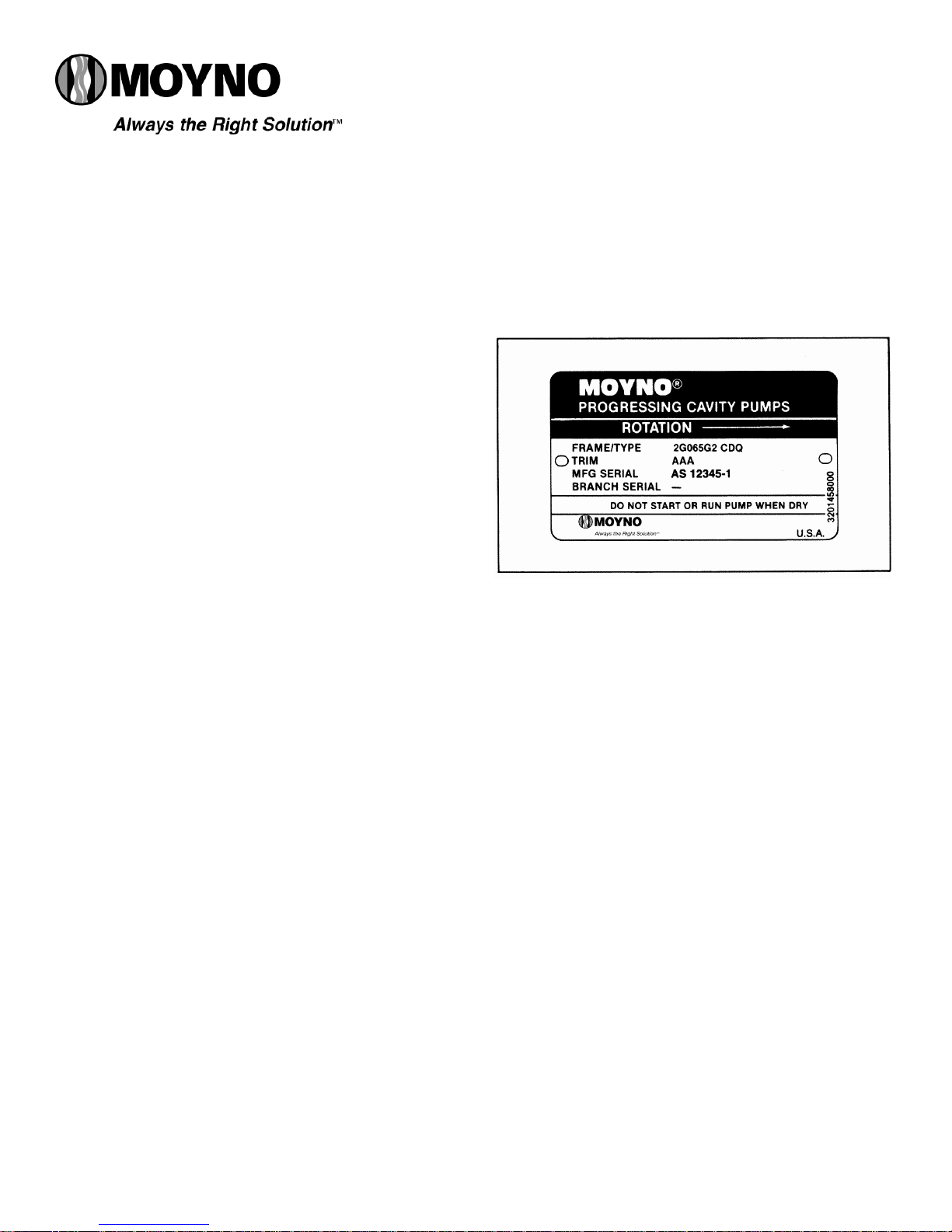
1.3. NAMEPLATE DATA
The pump nameplate, located on the bearing housing,
contains important information relating to the operation an d
servicing of the pump. This information includes the direction
of rotation arrow and the pump model and serial numbers
(see fig. 1-1).
The pump model number must be used for reference
when ordering spare parts. To simplify this procedure, the
model number for your pump has been recorded on the
nameplate drawing on the front cover of this manual. Please
carefully file this manual for further reference.
1.4. Pump Rotation. The direction of rotation is indicated by
a rotation arrow on the nameplate. Rotation of Moyno 2000
G2/G3 pumps is always clockwise, when viewed from the
driven end of the pump.
1-5. Model Number. The pump model number consists of
three component parts: Frame Designations, Type Designations and a Trim Code. A typical model number for example,
might be 2G065G2 CDQ AAA, as shown on the nameplate
in fig. 1-1.
1-6. Frame Designation. The Moyno 2000 is modular in
concept allowing for optimal matching of drive ends and
®
2000 Pump is the culmination of over
Section:
MOYNO® 2000 PUMPS
Page: 1
Date: October 2005
Figure 1-1. Typical nameplate showing rotation arrow,
model and manufacturing serial numbers.
pump elements (rotor and stator) to meet the requirements
of the application. The seven or more characters in the frame
designation describe the particular combination of drive end
and pump elements, as well as other construction details of
your pump.
The first character in the frame designation, always
a number, indicates the number of stages of the pumping
elements.
The second character is always a letter (E through K) and
indicates the drive end size.
The third, fourth and fifth characters are numbers indicating the theoretical capacity of the pumping elements per 100
revolutions.
The sixth character represents the type of universal joint
utilized. The letter G indicates a gear type joint. Other configurations may be indicated by the letters P or F.
The seventh character, a number, indicates the type of
suction housing. Flanged suction port pumps are d esignated
by the numeral “1,” open throat pumps by the numeral “2”
and open throat pumps with a bridge breaker option by the
numeral “3.”
1-7. Type Designation. Following the Frame Designation is the Type Designation, a series of three letters describing the materials from which the pump is constructed.
Page 2
The first letter identifies the material of the suction
housing.
C — Cast Iron
E — Carpenter 20 Stainless Steel
H — Hastelloy “C”
M — Monel
S — 316 Stainless Steel
W — Cast Steel
X — Special to application
Note: The bearing housing of the pump is always made
of cast iron.
The second letter indicates the material used in the
drive shaft, connecting rod, rotor and other wettable parts.
D — Alloy Steel
E — Carpenter 20 Stainless Steel
G — 416 Stainless Steel
H — Hastelloy “C”
J — 17-4 PH Stainless Steel
M — Monel
S — 316 Stainless Steel
X — Special to application
The third letter indicates the material of the stator. It identifies only the stator material and not that of the tube in which
the stator is placed, which is always carbon steel. Standard
stator materials used in the Moyno 2000 pump are as follows:
B — EPDM 300, 70 Durometer
C — Nitrile 103, 50 Durometer
D — Tool Steel
E — Nitrile 110, 70 Durometer
F — Fluoroelastomer 500, 75 Durometer
G — 416 Stainless Steel
H — Hastelloy “C”
J — 17-4 PH Stainless Steel
K — Hypalon 800, 70 Durometer
M — Nitrile 100M 70 Durometer
P — Thiokol 70 Durometer
Q — Nitrile 100, 70 Durometer
R — Natural Rubber 200, 55 Durometer
T — Teflon 15% glass
U — Urethane 70 Durometer
X — Special to application
Z — White Nitrile 150,70 Dur ometer
A typical type designation such as CDQ, would identify the
following materials of construction:
C = Cast iron suction housing
D = Alloy steel rotor, drive shaft, connecting
Q = Nitrite (70 durometer) stator
1-8. Trim Code. Also included in the Model Number is the
three character Trim Code which is used to identify pump
construction. The letters “AAA” signify standard construction,
with letters other than “A” signifying variations. The first letter
identifies sealing variations; the second, internal variations;
and the third, rotor variations.
1-9. Variations of Standard Parts. Refer to Sections 4-55
thru 4-57 for variations available for modifying pumps to
meet specialized pumping conditions. If the trim code of your
pump is other than “AAA,” contact your nearest Moyno representative for clarification. Do not modify your pump with
any variation unless you have determined that it is compa tible with your application.
rod and other minor metallic parts in contact with the fluid being pumped.
2-1. INSTALLATION
2.2. GENERAL
Moyno pumps are lubricated and tested at the factory
prior to shipment and require minimum pre-start up
maintenance.
Accessibility to the pump and adequate clearance should
be a prime consideration in any installation . Enough space
should surround the unit so that maintenance can be carried out with ease.
2-3. PIPING
2-4. Suction hopper used with open throat and bridge
breaker pumps should have nearly vertical sides, or be ot herwise designed to enhance the flow of the material i nto the
pump.
2-5. Discharge piping diameter should generally be as
large as the pump ports unless fluid conditions indicate
otherwise.
An easily removable section of piping one-to-two times
longer than the connecting rod should be mated to the discharge port. This will allow the rotor and stator to be removed without having to remove the complete pump from
the base.
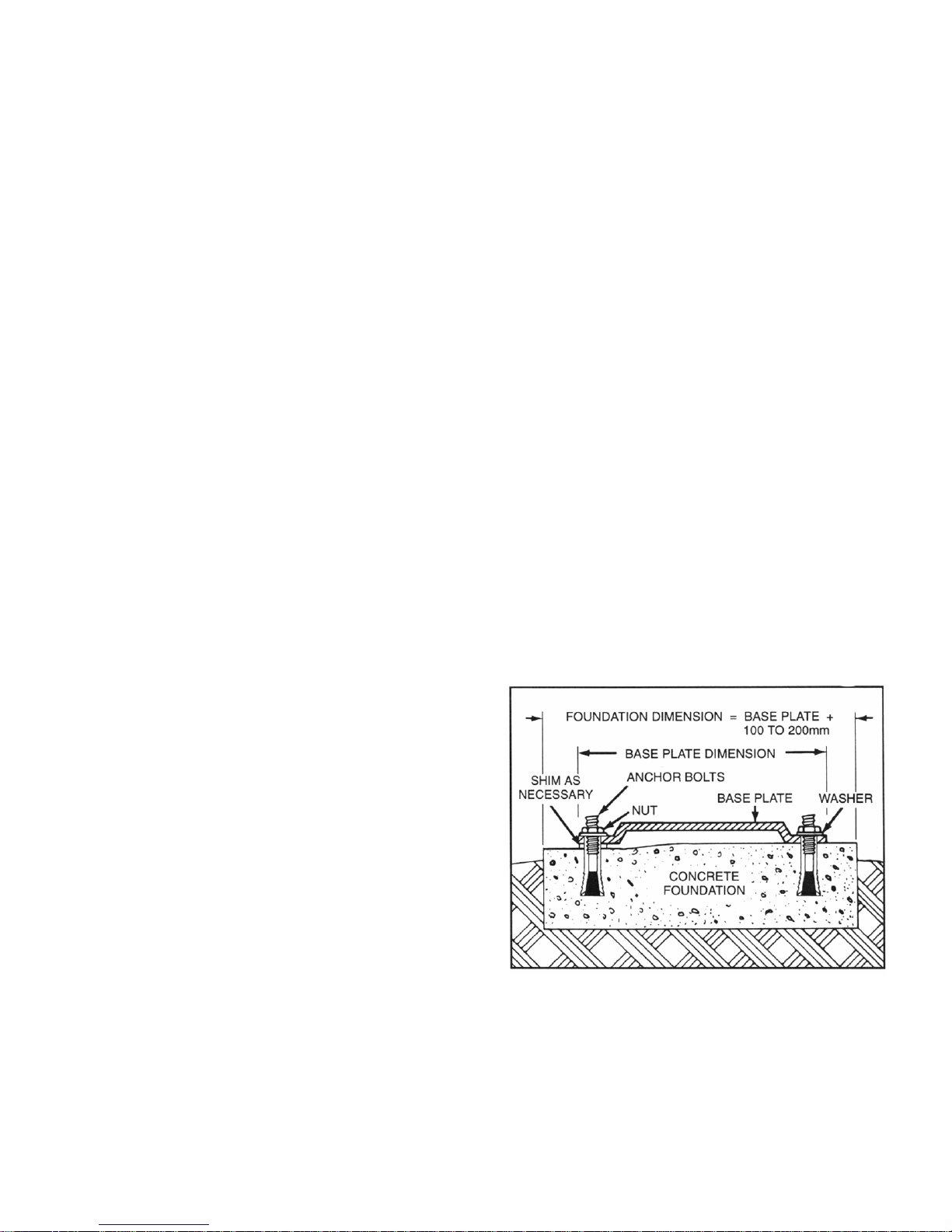
2-6. FOUNDATION
For maximum pump-driver unit life, each unit should be
mounted on a strong, fabricated-steel base plate which can
be ordered from Moyno. The base plate should be mounted
on a concrete foundation built on a solid base. The foundation
should be approximately 4” to 8” longer and wider than the
base for which it is buil t. (See fig. 2-1.) Anchor bolts for the
base plate should be located in the foundation.
Figure 2-1. Typical Foundation Example
Check the base plate surface with a carpenter’s level
and place shims under the base plate at the places
necessary to make it level. Then check the pump,
driver shaft and the pump ports to ensure that they are level.
Complete base mounted units supplied by Moyno including
pump and driver are leveled with respect to the base at the
factory. Shifting may occur during shipment. The pump and
driver should be realigned. Care should be exercised to ensure that all components are level and mou nted in a di rect line .
For maximum rigidity and lower noise levels the base
plate should be grouted to the foundation after the anchor
bolts have been evenly tightened. A good grade of nonshrink grout is recommended. The spaces between the base
plate and the foundation around the shims should also be
filled with grout. Allow the grout to dry according to manufacturer’s instructions, then fully tighten the anchor bolts.
2-7. SHAFT ALIGNMENT
Although the base-mounted units supplied by Robbi ns &
Myers are leveled with respect to the base before shipping,
most of the larger pump and driver units are shipped with the
flexible coupling disconnected.
After the base has been bolted down to the foundation,
check the following conditions:
2-8. On coupling connected units, be sure that the pump
and driver shafts are realigned before the coupling is connected. Care should be exercised to ensure that all compo nents are level and mounted in a direct line.
Check gap between coupling halves (refer to coupling
manufacturers recommendations). Adjustment can usually
be accomplished by loosening the mounting bolts on either
the pump or driver and moving the loosened component into
alignment with the fixed component. On couplings with equal
diameter hubs, it may be helpful to lay a straight edge axially
across the coupling halves to check alignment.
2-9. On belt drive units, check to ensure that sheaves or
sprockets are in alignment. Check belts for proper tension.
Tension requirements will vary with type of belt, center distances, and belt speeds. Consult belt manufacturer for specific recommendation.
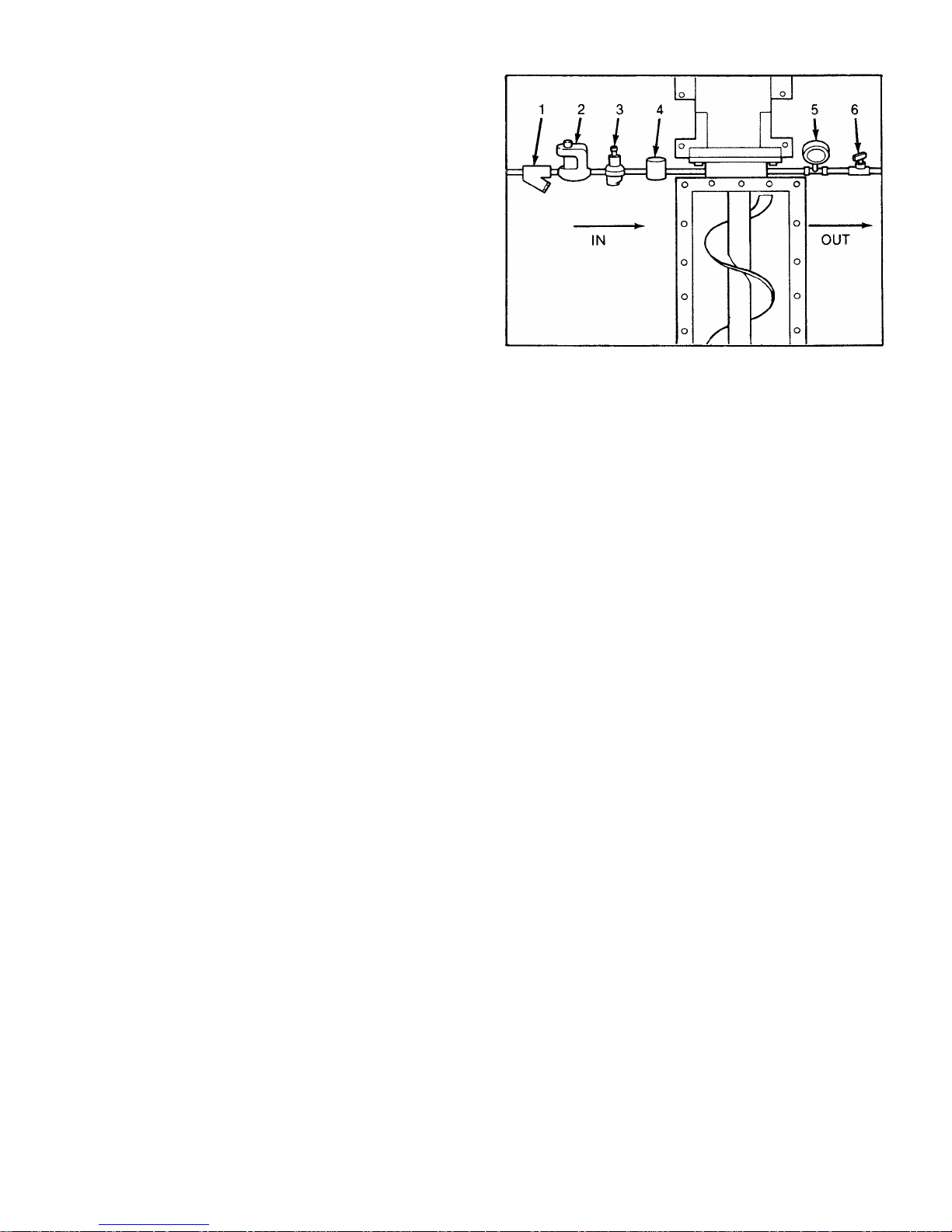
2-10. WATER FLUSH OF PACKING
The packing may be either grease lubricated through a
grease fitting in the stuffing box or have plumbing connected
to the housing to allow a water flush. Packing is not grease
lubricated at the factory prior to shipping.
When the material being pumped is abrasive, water flushing the packing is recommended to extend shaft life.
Clean water can be injected through a 1/8” NPT tapped
hole that normally houses the grease fitting for lubricating the
packing. The water can be permitted to leak axially along the
shaft in either direction or can be removed from the second
tapped hole in the stuffing box. In both cases, the discharge
from the stuffing box should be throttled slightly to maintain
10-15 PSI higher pressure in the stuffing box than is present
in the suction housing. (See fig. 2-2.) Flow rate should be
approximately 1/2-2 gpm.
If mechanical seals are to be used on the unit, consult the
seal manufacturers’ instructions for seal flush requirements.
3-1. OPERATION
3-2. INITIAL CHECK
Before putting the pump into operation, the following items
should be checked to ensure that each piece of equipment is
installed correctly:
— Pump, driver, coupling or sheave alignment.
Figure 2-2. Typical water flush arrangement for units
with packing includes strainer valve (1), sigh t flow meter
(2), pressure regulating valve (3), solenoid valve (4),
pressure gauge (5), and needle valve (6).
— Electrical connections
— Gauges and other instruments.
— Water flush connection to the stuffing box.
— Pump rotation. Normal rotation is indicated on the
— All valves should be open on both suction and
CAUTION: This is a positive displacement pump. Do not
3-3. START-UP
CAUTION: DRY OPERATION IS HARMFUL TO THE PUMP!
Never allow the pump to operate w ithout liquid,
1. Before operating the pump for the first time, fill it with
liquid (the pipe plug tap on the suction housi ng may be used
for filling). If the liquid to be pumped is highly viscous, dilute
it before filling the pump. The liquid fill-up will lubricate the
stator for the initial start-up.
Note: If the pump is shut down temporarily, enough liquid
2. Once the pump has been filled with liquid, check for d irection of pump rotation by momentarily starting and stopping the drive. Check rotation arrow on pump nameplate for
correct rotation.
3. If applicable, turn on the seal water to packing.
4. Start pump.
3-4. PACKING LEAKAGE
A packed stuffing box is designed to control le akage, not
stop it completely. Leakage is generally necessary to reduce
friction and dissipate heat. The amount of leakage necessary
will depend on the fluid pumped, the install ation, and pump
speed and type. Refer to Section 4-3 for packing adjustment.
nameplate on the bearing housing.
discharge sides of pump.
operate it against a closed valve.
as dry operation will cause premature wear of
the stator and possible damage. The stator is
lubricated by the liquid which is pumped.
will remain in the system to provide lubrication upon
restarting. It is advisable to maintain the suction piping at a higher elevation than the centerline of the
pump in order to contain some liquid in the pump at
time of shutdown.
Page 3
Page 4
Moyno 2000 pumps have been designed for minimum
stuffing box leakage when properly maintained. If leakage
cannot be tolerated, then a mechanical seal should be used.
3-5. G3 DRIVE ASSEMBLY ADJUSTMENT
Ensure that the chain on the drive assembly has no bows.
The chain tension can be adjusted by loosening or tig htening
the idler adjusting screw (E, F,fig. 4-10).
The chain tension should be checked again and readjusted after the first 20 hours of operation.
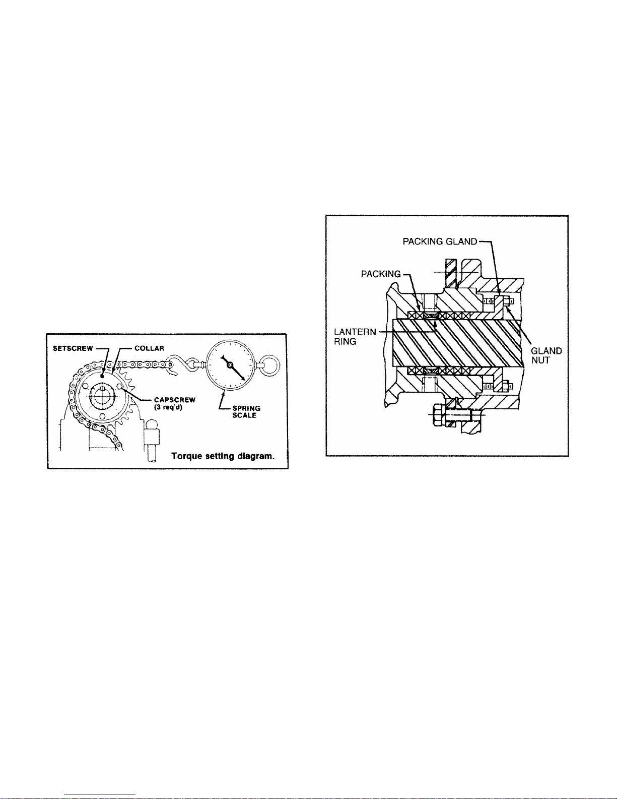
The assembled torque limiter (3) and sprocket (4) on the
bridge breaker assemblies are set at the factory to a reading
of 540 lbs on a spring scale. (See fig. 3-1.) If during operation the torque limiter slips, the torque should be checked
and if necessary, reset. To check the torque limiter setting,
use a spring scale as shown in the di agram with a properly
sized chain to fit the sprocket (4). Attach the scale to the
chain and pull, noting the value on the scale dial when the
torque limiter slips. To adjust the torque, loosen the three
capscrews on the torque limiter collar. Turn the collar clockwise to increase torque, or counter-clockwise to decrease it.
Tighten capscrews until heads bottom and again check the
torque setting. Repeat this process until the slipping point is
within 5 lbs of the 540 lb value. When the correct torque is
achieved, tighten setscrew to lock collar in position.
1. Upon initial start-up of the pump, adjust the gland nuts
for a leakage rate of 1-2 drops per second until the packing
has seated and adjusted to the operatin g temperature (approximately 10-15 minutes).
2. If leakage is excessive after 15 minutes of operation,
tighten the gland nuts until a desired leakage rate is obtained.
CAUTION: Do not tighten until zero leakage is obtained.
Over-tightening of the packing gland may
result in accelerated wear on the packing
and damage to the shaft. In those situations
where no packing leakage can be tolerated,
consult your Moyno Authorized Service
Representative.
Figure 3-1. Torque Setting Diagram
4-1. MAINTENANCE
Note: In this section, the first reference to each pump part
will be followed by a number or a letter in parentheses
( ). These numbers and letters are those used to identify the pump parts and hardware items in the foldout
Exploded Views (fig. 4-7 or 4-10 as indicated).
4-2. GENERAL
The Moyno 2000 pump has been designed for a minimum
of maintenance, the extent of which is routine adjustment
and lubrication of packing. The pump is one of the easiest to
work on, in that the main elements are very accessible and
require few tools to disassemble.
4-3. PACKING ADJUSTMENT
Pumps. Packing gland nuts should be evenly adjusted so
they are little more than finger tight. (See fig. 4-1.) Overtightening of the packing gland may result in premature
packing failure and possible damage to the shaft and gland.
When packing is new, frequent minor adjustments during
the first few hours of operation are recommended in order to
compress and seat the packing.
Figure 4-1. Cross Section of Stuffing Box
Bridge Breaker. Packing for the bridge breaker is ad-
justed by means of cylindrical packing glands (25, fig. 4-10)
which are threaded into the bearing retainers (28). Holes in
the packing gland allow the use of a punch to rotate the
gland. The packing is compressed by rotating the gland i n a
clockwise direction when viewed from the shaft end.
4-4. PACKING REPLACEMENT
When leakage can no longer be regulated by tightening
the gland nuts, remove and replace the packing. The entire
pump need not be disassembled to replace the packing.
Briefly, replace as follows:
1. Remove packing gland nuts (E, fig. 4-7), and slide
gland (12) and slinger ring (11) back along drive shaft (4).
2. Use a pair of packing extractors (fig. 4-2) to remove
three packing rings (10), lantern ring halves (13) a nd three
additional packing rings (10).
3. Inspect surface of drive shaft for excessive wear or
grooves due to packing rub. If shaft is worn, or is badly
scored or grooved, it should be replaced.
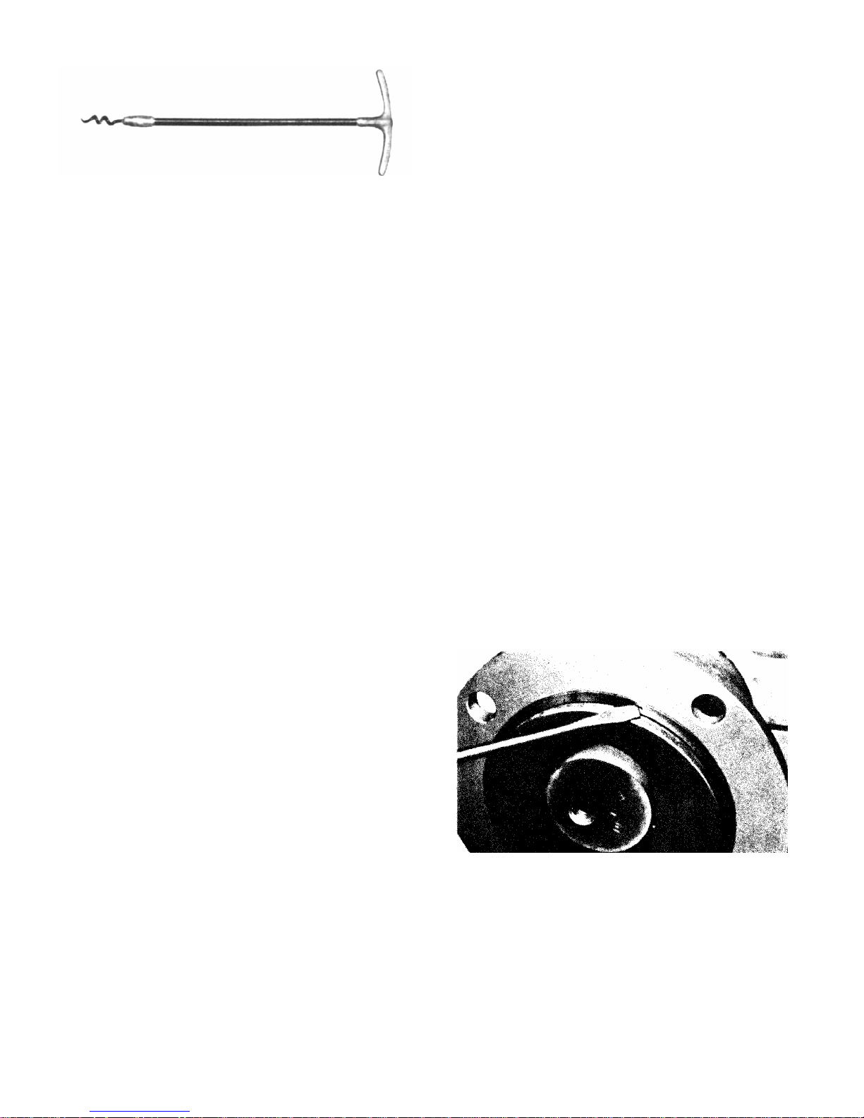
Figure 4-2. Packing Removal Tool
4. If drive shaft is not worn, install three rings of packing,
the lantern ring halves, and four more rings of packing; lubricating them before installation with a good grade of packing
grease. Be sure to stagger the packing ring joints at 90° increments. (See Section 4-35.)
CAUTION: Always use a proper packing tamp er tool to
install packing. Do not use a pointed or
sharp tool, as damage to the packin g material or drive shaft could result. To assure
proper shaft lubrication, never use a onepiece spiral wrap packing.
5. Replace packing gland and secure with packing gland
nuts. (See fig. 4-1.)
6. Adjust packing per Section 4-3.
4.5. LUBRICATION
4.6. Bearings. The bearings are lubricated at the factory
and will only need to be re-lubricated when the shaft/bearing
assembly is removed from the pump. (See Section 4.34.)
4-7. Gear Joints. Both gear joints are packed with lubricant during assembly, and will only need to be re-lubricated
when gear joints are disassembled. (See Section 4-34.)
4-8. G-3 Oilers. Ensure that both oilers (item 1, fig. 4-10)
are filled with a suitable SAE 30 or 40 weight oil.
4-9. DISASSEMBLY OF G2 OPEN THROAT PUMP
Note: In the following G2 disassembly instructions, the part
reference numbers are from fig. 4-7.
Note: The following instructions cover ONE procedure for
disassembling all pump components. Major pump
components can be disassembled in various ways
since specific installation location limitations will determine method of component removal.
4-10. Disconnect Pump
1. Operate pump (preferably with clean water) to insure
rotor and stator are not dry.
2. Shut off pump.
3. Close suction and discharge valves.
4. Turn off flush water to packing or mechanical seal,
if used.
5. Disconnect power source.
6. Drain any fluid in pump.
7. Remove inspection plate (17) and gasket (18).
Page 5
4-11. Packing Removal
1. Stop pump.
2. Complete Section 4-10, steps 2 - 6.
3. Remove gland adjustment nuts (E) and gland halves
(12) from stuffing box.
4. Remove packing rings (10). This is best done by using
flexible packing extractors (see fig. 4.2). Use two extractors
simultaneously on opposite sides of each ring. Pull evenly.
5. Remove lantern rings (13) in similar fashion. Twist split
rings to remove from shaft.
6. Remove additional packing rings.
4-12. Stator Removal
1. Complete Section 4-10.
2. Remove section of discharge pipe attached to discharge flange (45).
3. Remove discharge flange (45) by unbolting from stator
clamp ring (40B) and remove stator gasket (42). Remove
stator retaining ring (43) and stator clamp ring (40B) from
stator (44).
Note: Omit above step 3 when using following method 6a to
separate rotor and stator.
4. Remove top half of stator support (41).
5. Unbolt stator clamp ring (40A) from adapter flange
(21) and suction housing (19). Remove stator gasket (42).
Use a screwdriver tip to carefully remove stator retaining
ring (43). (See fig. 4-3.) Remove stator clamp ring (40A)
from stator (44).
Figure 4-3. Typical Retaining Ring Removal
6. Pull stator (44) off rotor (37).
Note: On multiple stage pumps, or when also cleaning,
checking or changing stator (44), rotor (37) and/or
gear joint assembly, one of the following procedures
is suggested.
6a. Use winch-type device if anchored directly opposite
stator end. Attach cable to discharge flange (45) to pull stator (44) off rotor (37).

Page 6
6b.Hold stator (44) with pipe or strap wrench and turn
drive shaft (4) clockwise to force stator (44) off rotor (37).
7. Check rotor (37) and stator (44) for wear. See Rotor
(4-30) and Stator (4-31) for instructions.
4-13. Rotor Removal
1. Complete sections 4-9 and 4-11.
2. Remove stator adaptor (21) and O-ring (20) from suc-
tion housing (19).
3. Remove hopper or suction piping from suction
housing (19).
4. Remove socket head pipe plug (P) and set screw (Q)
from gear joint shell (36).
5. While supporting weight of rotor, remove six socket
head screws (N) from head ring (39), and slide head ring
(39) and O-ring (38) off rotor. Separate rotor from gear joint.
Note: If rotor-end gear joint is not accessi ble, disassemble
drive-end gear joint by following the procedure in section 4-14, steps 1-3. Then remove both the conveyor
assembly and rotor from suction housing as a single
unit.
4-14. Gear Joints and Conveyor Assembly Removal
1. Complete sections 4-9 thru 4-12.
2. Remove pipe plug (P) from gear joint shell (33).
Remove six socket head screws (N) from gear joint retainer
(34), and slide retainer and O-ring (24) toward conveyor
flight.
3. Pull conveyor assembly (35) from drive-end gear joint
until it is separated from gear joint shell (33) and completely
separated from suction housing (19).
4. Remove lock nut (28) from drive-end of conveyor assembly, and slide gear ball (29), secondary thrust plate (30) ,
seal support (31), gear joint seal (32), and gear joint retain er
(34) from conveyor assembly.
5. Remove two keys (26), ring gear (27), and primary
thrust plate (25) from gear joint shell (33).
6. The other gear joint is disassembled in a similar manner by first removing primary thrust plate (25) from rotor
head. Remove two keys (26) from gear joint shell.
7. Slide gear joint shell (36) toward flight on conveyor
assembly. Remove lock nut (28) from end of conveyor
assembly (35). Remove ring gear (27), gear ball (29),
secondary thrust plate (30), seal support (31), and gear
joint seal (32). Then slide gear joint shell (36) from conv eyor
assembly.
Note: It is recommended that each time a gear joint is dis-
assembled, the O-rings and grease seal should be
replaced.
4-15. Drive Shaft and Bearings Removal
1. Complete sections 4-9 thru 4-13.
2. Remove drive coupling or V-belts and pulleys
from drive shaft (4).
3. Remove four socket head screws (O) from shaft
adapter (23), and remove adapter and gear joint shell (33)
from end of drive shaft (4).
4. Remove six hex head screws (A) from bearing cover
plate (2). Slide bearing cover plate (2) along with radial
grease seal (1) and O-ring (3) off drive shaft.
5. Drive shaft (4) and bearings can now be pulled out of
bearing housing (14), taking steps to support the weight of
the assembly as the bearings clear the housing. Remove
grease seal (9) from bearing housing (14).
CAUTION: The bearings are pressed on the shaft during
assembly. Care must be taken during
disassembly to avoid damaging the
bearings or shaft.
6. Remove bearing lock screw (7) from bearing nut (8).
Using suitable spanner wrench or soft pun ch and hammer,
thread lock nut off drive shaft.
7. Remove both halv es of bearing spacer (6) from shaft,
and using suitable bearing press and adaptors, press bearings off shaft.
4-16. DISASSEMBLY OF G3 BRIDGE BREAKER
Note: In the following G3 disassembly instructions, the part
reference numbers are from fig. 4-10.
4-17. Disconnect Pump
1. Shut off pump.
2. Turn off flush water to packing or mechanical seal,
if used.
3. Disconnect power source.
4. Drain any fluid in pump.
4-18. Chain Replacement
1. Complete section 4-17, steps 1-3.
2. Remove oiler (1), oiler nozzle (1A), and guard (12).
3. Loosen idler arm adjusting screw (F) and remove
chain (9).
4. Install and connect chain (9). Tighten idler
adjusting screw (F). (See Section 3-5 for instructions
on chain tension.)
 Loading...