

moyno 331, 333, 332, 344 Service Manual
Section:
MOYNO®500 PUMPS
Page: 1 of 4
Date: March 2002
SERVICE MANUAL
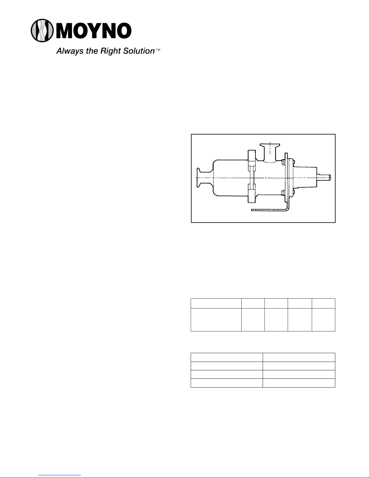
MOYNO®500 PUMPS
SANITARY/HYGIENIC NON-MOTORIZED
331, 332, 333 AND 344 MODELS
SANITARY MODELS
These pumps include housings polished to a #4 finish
both inside and out. The mechanical seal is a 3A approved
seal with carbon/ceramic faces. The elastomers meet the
FDA requirement for food contact. These pumps meet 3A
requirements. The universal joint may be dismantled for
cleaning.
HYGIENIC MODELS
These pumps provide the quick disassembly features
of the sanitary version for easy cleaning. The housings
are 316 stainless steel construction, however, they
are not polished. These pumps utilize rubber-covered
universal joints.The stators are available in non-FDA nitrile,
EPDM, and fluoroelastomers. The mechanical seals are
rubber bellows type with carbon/ceramic faces.
INSTALLATION
Mounting Position.Pump may be mounted in an y position.
When mounting vertically, it is necessary to keep the
bearings above the seals to prevent possible seal leakage
into the bearings.
Pre-Wetting. Prior to connection the pump, wet the pump
elements and mechanical seal by adding fluid to be
pumped into suction and discharge ports.Turn the shaft over
several times in a clockwise direction to work fluid into the
elements.
Piping. Piping to the pump should be self-supporting
to avoid excessive strain on pump housings.
Drive. On belt driven units, adjust belt tension to point
of non-slip.Do not overtighten.
On direct drive units, coupling components should be
aligned and spaced at least 1/16" apart.
Pump rotation must be clockwise when facing shaft to prevent damage to pump. Check direction of rotation before
startup. Maximum speed is 1750 rpm.
Table 1. Pump Data
Table 2.Temperature Limits
Pump Models
Discharge
Pressure
(psig) (maximum)
331 332 333 344
150 100 50 40
Elastomer Temperature Limits
*NBR (Nitrile) 10˚-160˚F
*EPDM 10˚-210˚F
FPM (Fluoroelastomer) 10˚-240˚F
* FDA Food Grade on Sanitary Models.

OPERATION
Self-Priming. With wetted pumping elements, the pump
is capable of 25 feet of suction lift when operating at 1750
rpm with pipe size equal to port size.
DO NOT RUN DRY. The unit depends on liquid pumped
for lubrication. For proper lubrication, the flow rate should
be at least 10% of rated capacity.
Pressure and Temperature Limits. See Table 1 for maximum discharge pressure of each model.The unit is suitable
for service at temperatures shown in Table 2.
Storage. Always drain the pump for extended storage
periods by removing the suction housing and stator.
TROUBLESHOOTING
WARNING: Before making adjustments, disconnect
power source and thoroughly bleed pressure from system prior to disassembly.
Failure to do so could lead to electric
shock or serious bodily harm.
Failure T o Pump.
1. Belt or coupling slip: Adjust belt tension or tighten set
screw on coupling.
2. Stator torn; possibly excessive pressure: Replace
stator and check pressure at the discharge port.
3. Wrong rotation: Rotation must be clockwise when
facing shaft.
4. Threads in rotor or on shaft stripped: Replace part.
Check for proper rotation.
5. Excessive suction lift or vacuum.
Pump Overloads.
1. Excessive discharge pressure: Check discharge
pressure for maximum rating given in Table 1. Check for
obstruction in discharge pipe.
2. Fluid viscosity too high: Limit fluid viscosity to 20,000
CP or 100,000 SSU.
3. Insufficient motor HP: Check HP requirement, consult
factory.
Noisy Operation.
1. Starved suction: Check fluid supply, length of suction
line, and obstructions in pipe.
2. Bearings worn: Replace parts; check alignment, belt
tension, pressure at the discharge port.
3. Broken flexible joint: Replace part, check pressure at
the discharge port.
4. Insufficient mounting: Mount to be secure to firm
base. Vibration induced noise can be reduced by using
mount pads.
Mechanical Seal Leakage.
1. Leakage at star tup: If leakage is slight, allow pump to
run several hours to let faces run in.
2. Persistent seal leakage: Faces may be cracked from
freezing or thermal shock. Replace seal.
Pump Will Not Prime.
1. Air leak on suction side: Check pipe connections.
MAINTENANCE
General. These pumps have been designed for minimal
maintenance — routine lubrication and adjustment of packing. The pump is one of the easiest to work on because
the main elements are very accessible and require no tools
to disassemble.
Bearing Lubrication. The prelubricated, fully sealed bear-
ings do not require additional lubrication.
PUMP DISASSEMBLY
WARNING: Before disassembling pump, disconnect
power source and thoroughly bleed
pressure from system. Failure to do so
could result in electrical shock or serious
bodily harm.
1. Disconnect suction and discharge piping.
2. Remove quick clamp (80) holding suction housing
(2) to pump body (1A). Remove suction housing and
stator (21).
3. Remove rotor (22) from flexible joint (24) by turning
counterclockwise (RH thread).
4. Flexible joints (24) can be removed from shaft (26)
by turning counterclockwise with a 3/16 Allen wrench.
Universal joints in the sanitary pump may be further
disassembled by removing the snap rings, allowing the
pins to be removed.
5.Carefully slide the mechanical seal (69) off the shaft (26).
Carefully pry the seal seat out of the pump body (1A). If any
parts of the mechanical seal are worn or broken, the complete seal assembly should be replaced. Seal components
are matched parts and are not interchangeable.
6. The bearings (29) and shaft (26) assembly can be
removed from pump body (1B) after the snap ring (66) has
been removed.To remove the assembly, lightly tap the shaft
at threaded end using a block of wood to protect the
threads.The bearings may be pressed off the shaft.
Page 2
Viscosity CP Limit RPM
1-300 1750
300-1,000 1200
1,000-2,000 700
2,000-5,000 350
5,000-10,000 180
10,000-20,000 100
 Loading...