

moyno 20352, 20452, 20551, 20552, 22051 Service Manual
...
SERVICE MANUAL
DESIGN FEATURES
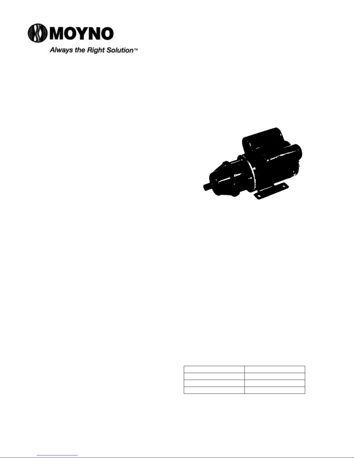
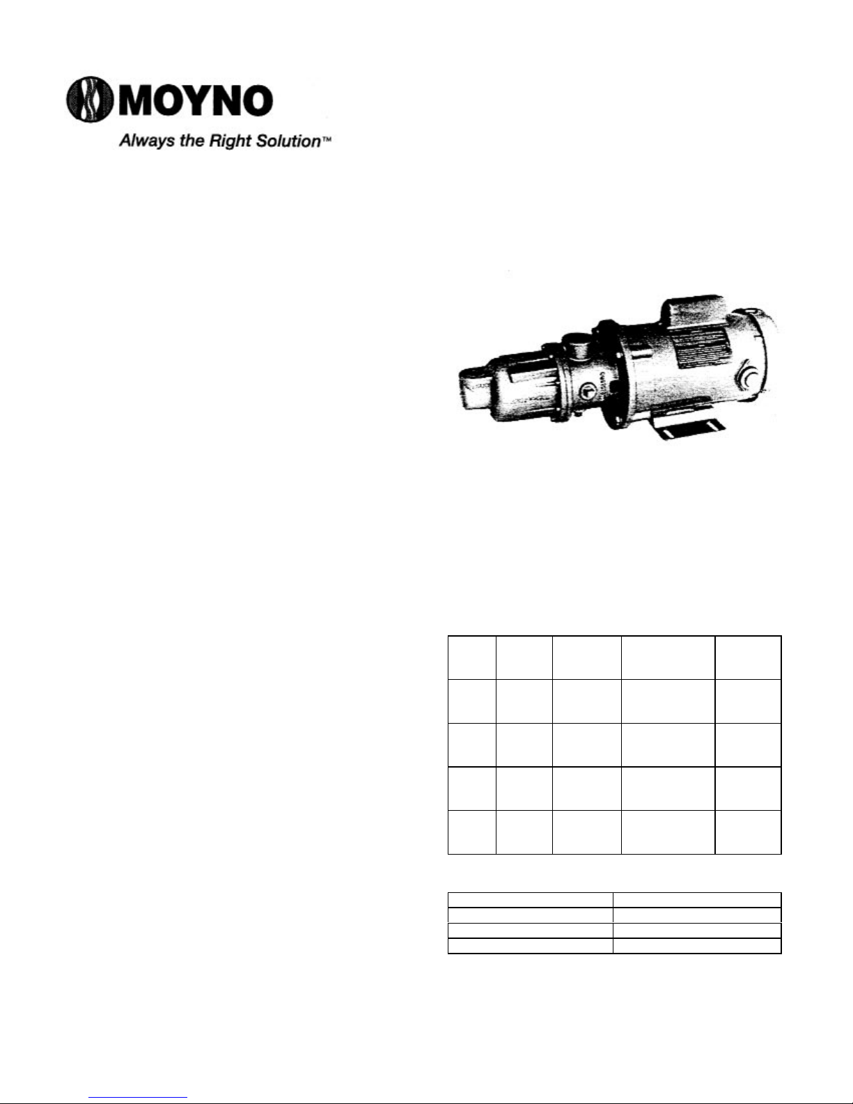
MOYNO® 500 PUMPS
200 SERIES MOTORIZED
20352, 20452, 20551, 20552, 22051 AND 22052
MODELS
Housing: AISI 316 stainless steel, or phenolic
Pump Rotor: Phenolic, AISI 316 stainless steel
Pump Stator: NBR (Nitrile)
Seal: Mechanical (carbon/ceramic)
Motor Shaft: AISI 316 stainless steel
Motor: 115V AC, 1/8 HP, 50/60 Hertz, 1725 rpm,
ball bearing, Class B insulation, capacitor
start (other motor options available;
consult Sales Representative)
Section:
MOYNO® 500 PUMPS
Page:1 of 4
Date: March 1, 1998
Note: Alternate elastomers available. Refer to
Repair/Conversion kit numbers, page 3.
INSTALLATION
Mounting Position. Pump may be mounted
in any position. When mounting vertically, it
is necessary to keep bearings above seals
to prevent possible seal leakage into
bearings.
Pre-Wetting. Prior to connecting pump, wet
pump elements and mechanical seal by
adding fluid to be pumped into suction and
discharge ports. Turn pump over several
times in a clockwise direction using
screwdriver slot in end of motor shaft.
Piping. Piping to pump should be selfsupporting to avoid excessive strain on
pump housings; 3/8” NPT pipe for suction,
and. 1/4” NPT pipe for discharge on all metal
housing models. 5/8” ID hose with hose
clamp for suction and discharge ports of
plastic housing models. Use pipe “dope” or
tape to facilitate disassembly and to provide
seal on pipe connections.
Electrical. Follow the wiring diagram on the
motor nameplate or inside the terminal box
for the proper connections. The wiring
should be direct and conform to local
electrical codes. Check power connections
for proper voltage. Voltage variations must
not exceed ± 10% of nameplate voltage.
Motor is provided with internal automatic
overload protection.
To prevent damage to pump, pump rotation
must be clockwise when facing pump from
motor end.
OPERATION
Self-Priming. With wetted pumping
elements, the pump is capable of 25 feet of
suction lift with pipe size equal to port size.
Be sure suction lines are air tight or pump
will not self-prime.
DO NOT RUN DRY. Unit depends on liquid
pumped for lubrication. For proper
lubrication, flow rate should be at least 10%
of rated capacity.
Pressure and Temperature Limits.
Maximum discharge pressure is 40 psig.
Unit is suitable for service at temperatures
shown in Table 1.
Storage. Always drain pump for extended
storage periods by removing suction
housing bolts and loosening suction
housing.
Table 1. Temperature Limits
Elastomer Temperature Limits
*NBR 10°-160°F
*EPDM 10°-210°F
*FPM 10°-240°F
*NBR = Nitrile
EPDM = Ethylene-Propylene-Diene Terpolymer
FPM = Fluoroelastomer

Page 2
TROUBLE SHOOTING
WARNING:Before making adjustments,
disconnect power source and
thoroughly bleed pressure
from system. Failure to do so
could result in electric shock
or serious bodily harm.
Failure To Pump.
1. Motor won’t start: Check power supply.
Voltage must be ± 10% nameplate rating
when motor is in locked rotor condition.
Do not use less than #14 wire size.
2. Motor runs and thermally kicks out:
Increase ventilation to motor. Check for
defective relay, or defective capacitor.
Check for excessive pressure.
3. Stator torn; possibly excessive pressure:
Replace stator, check pressure at
discharge port.
4. Excessive suction lift or vacuum.
Pump Overloads.
1. Excessive discharge pressure: Check
discharge pressure for 40 psig maximum
or obstruction in discharge line.
2. Fluid viscosity too high: Limit fluid
viscosity to 100 CP or 500 SSU.
Noisy Operation.
1. Starved suction: Check fluid level, size of
piping. and obstructions in pipe.
2. Bearings worn: Replace parts
3. Insufficient mounting: Mount securely.
Reduce vibration induced noise by using
a short section of hose on discharge
piping.
Seal Leakage.
1. Leakage at startup: If leakage is slight,
allow pump to run several hours to let
faces run in.
2. Persistent seal leakage: Faces may be
cracked from freezing or thermal shock.
Replace seal.
Pump Will Not Prime.
1. Air leak on suction side: Check pipe
connections.
PUMP DISASSEMBLY
WARNING:Before disassembling pump,
disconnect power source and
thoroughly bleed pressure
from system. Failure to do so
could result in electric shock
or serious bodily harm.
1. Remove suction and discharge piping.
2. Remove screws (112) holding suction housing (2)
and pump body (1) to motor (70). Remove
suction housing (2) and stator (21).
3. Remove rotor (22) from shaft by turning in a
counterclockwise direction. Keep shaft from
turning by inserting screwdriver in slotted end of
motor shaft.
4. Remove slinger ring (110), pump body (1), and
mechanical seal (69).
5. If any parts of the mechanical seal (69) are worn
or broken, the complete seal assembly should be
replaced. Seal components are matched parts
and are not interchangeable.
PUMP ASSEMBLY
1. Slip slinger ring (110) over motor shaft. Place
pump body (1) in position on motor (70).
2. Install mechanical seal (69) using the following
procedure:
a. Clean and oil sealing faces using a clean light
oil (not grease).
Caution: Do not use oil on EPDM parts. Substitute
glycerin or soap and water.
b. Oil the outer surface of the seal seat, and
push the assembly into the seal bore in the
pump body (1), seating it firmly and squarely.
c. After cleaning and oiling the shaft, slide the
seal body along the shaft until it meets the
seal seat.
d. Install seal spring and spring retainer on shaft.
3. Screw rotor (22) on shaft in a clockwise direction.
Keep shaft from turning by inserting screwdriver
in slotted end of motor shaft.
4. Secure stator (21), suction housing (2), and pump
body (1) to motor (70) using screws (112).
5. Connect hose or piping and proceed as in
installation instructions.
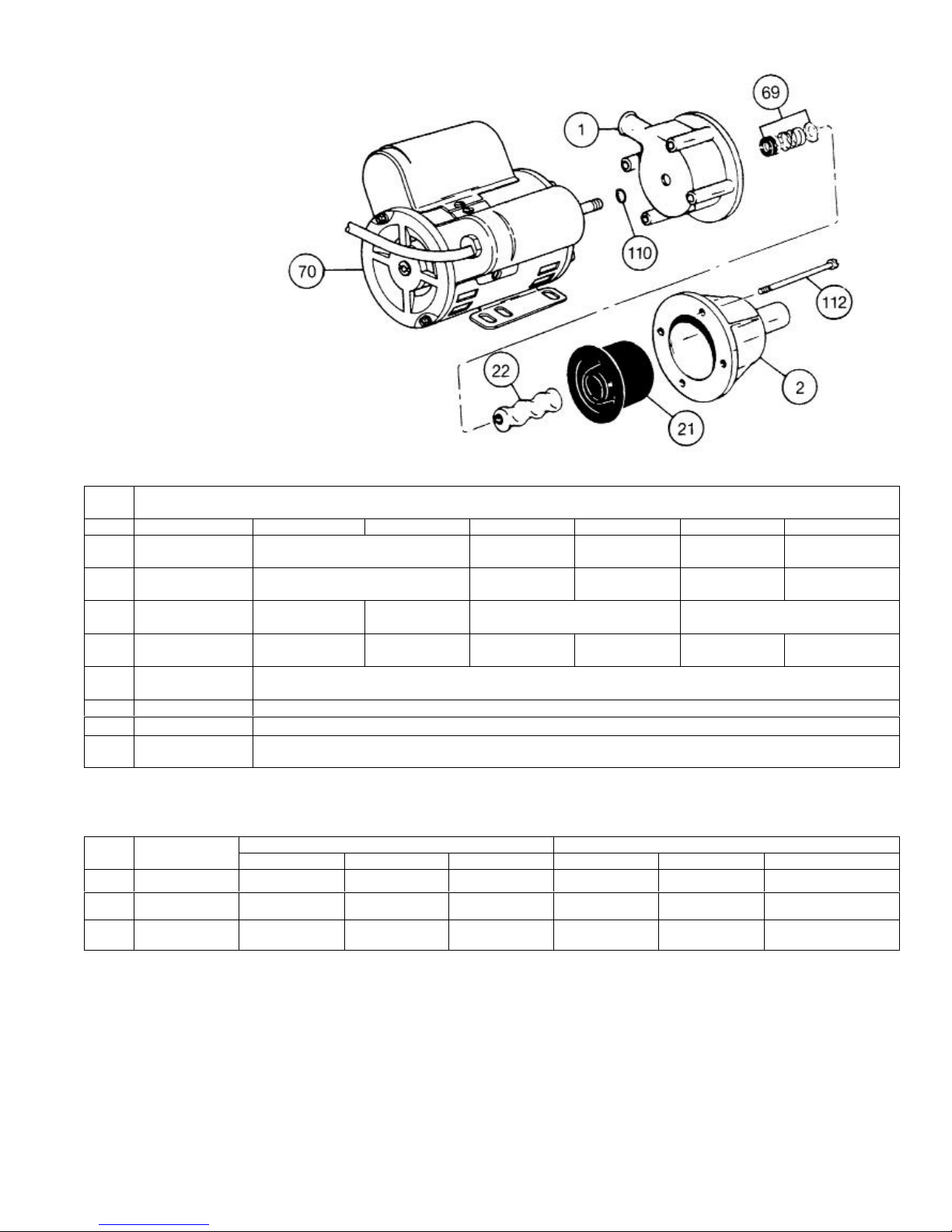
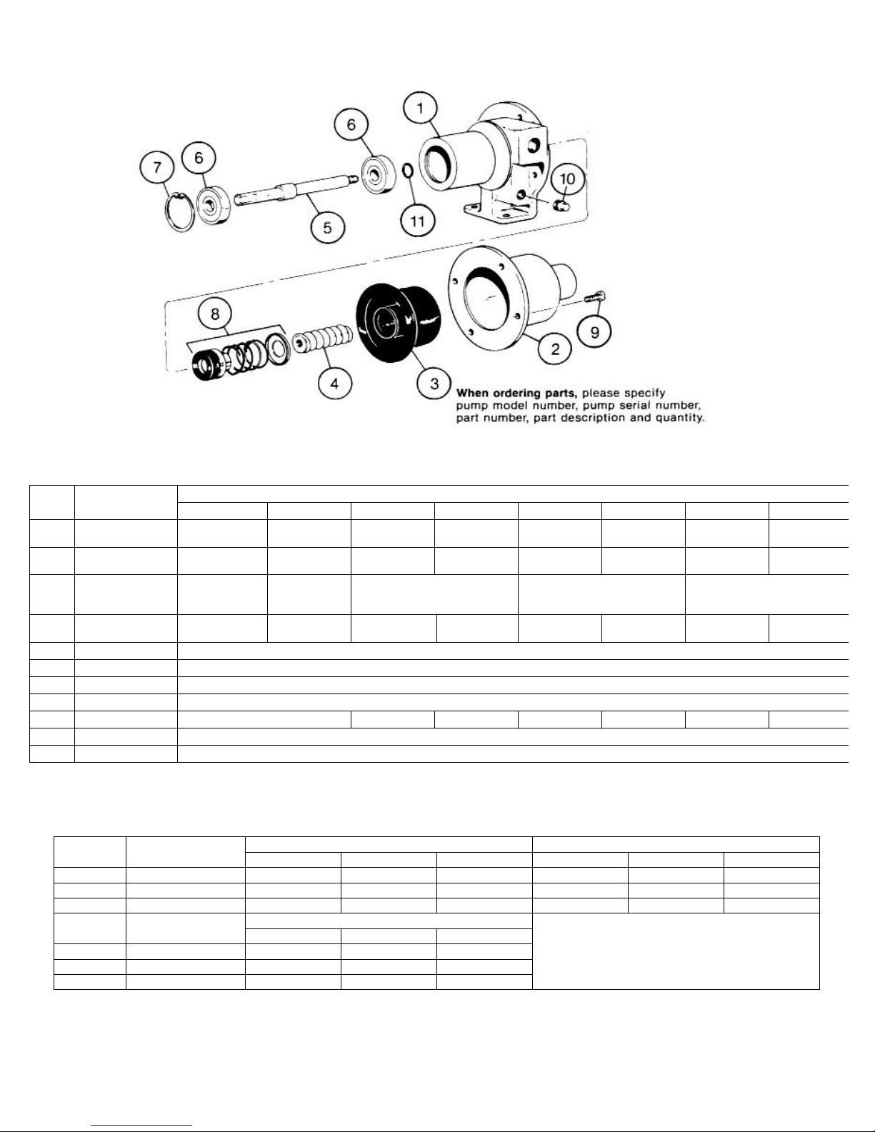
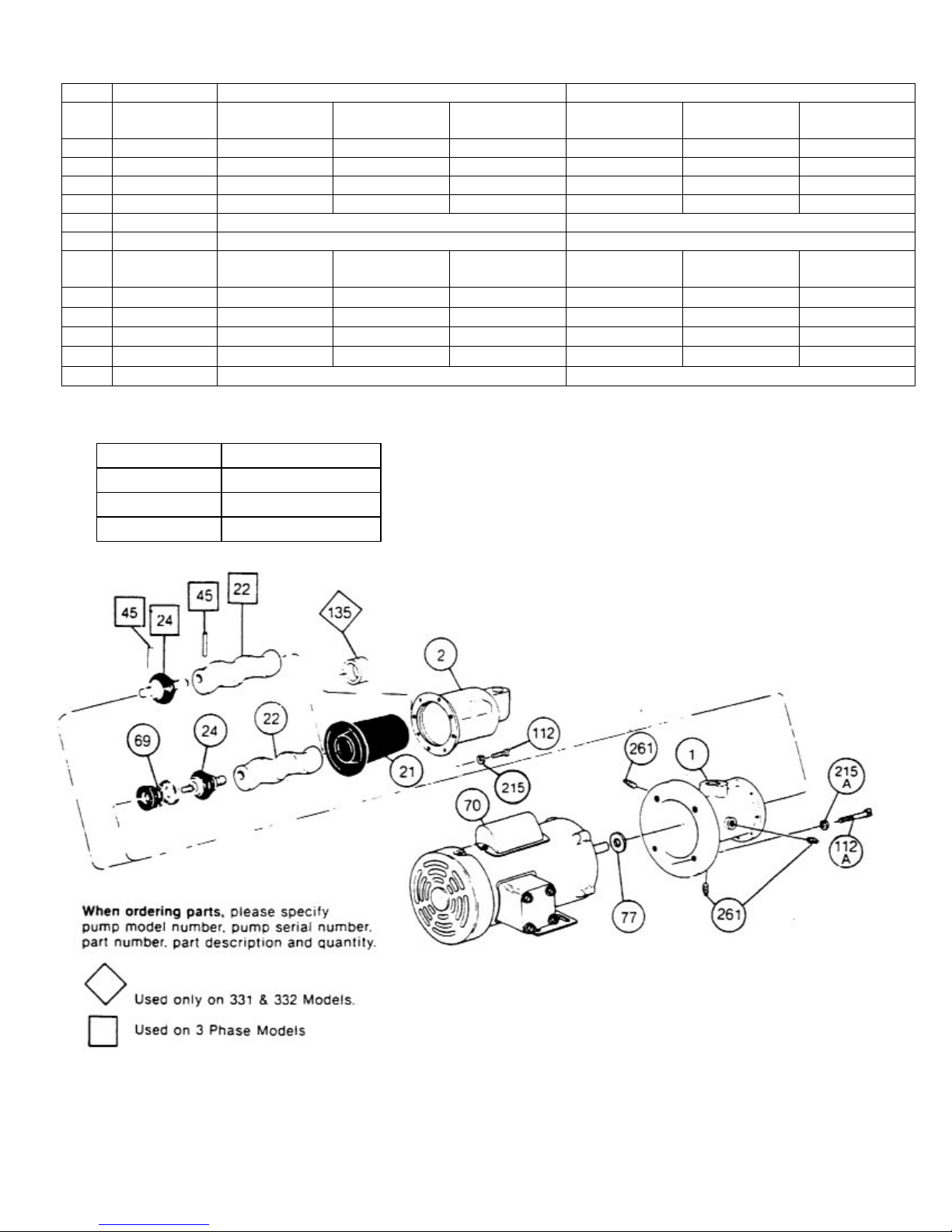
When ordering parts, please specify
pump model number, pump serial
and quantity.
PARTS LIST
Page 3
number, part number, part description
Item
No.
Pump Model Numbers
Description 20352 20452 20551 20552 22051 22052
1 Pump Body
Suction
2
Housing
Stator
*21
Rotor
*22
Mechanical
*69
Seal
70 Motor
Slinger Ring
110
Screws (4
112
req.)
*Recommended spare parts.
316 SS
330-3330-000
316 SS
330-3327-000
NBR
330-7555-120
316 SS
320-6975-000
NBR
330-7556-120
316 SS
320-7923-000
Phenolic
330-2953-000
Phenolic
330-2954-000
330-6381-120
Phenolic
320-6485-000
320-6480-000
330-4596-000
320-2833-008
619-0050-301
316 SS
330-3330-000
316 SS
330-3327-000
NBR
316 SS
320-6484-000
NBR
Phenolic
330-2953-000
Phenolic
330-2954-000
330-6382-120
Phenolic
320-6488-000
316 SS
330-3330-000
316 SS
330-3327-000
NBR
316 SS
320-6487-000
REPAIR/CONVERSION KIT NUMBERS (Not available as kit for 20352, 20452 Models)
Description
No.
- Kit No. 311-9116-000 311-9118-000 311-9120-000 311-9117-000 311-9119-000 311-9121-000
21 • Stator 330-6381-120 330-6381-320 330-6381-520 330-6382-120 330-6382-320 330-6382-520
69 • Seal 320-6480-000 320-6481-000 320-6482-000 320-6480-000 320-6481-000 320-6482-000
205 Models 220 ModelsItem
NBR EPDM FPM NBR EPDM FPM
NBR = Nitrile
EPDM = Ethylene-Propylene-Diene Terpolymer
FPM = Fluoroelastomer

© 1999 by Moyno, Inc. Printed in U S.A
® Moyno is a registered trademark of Moyno Inc.
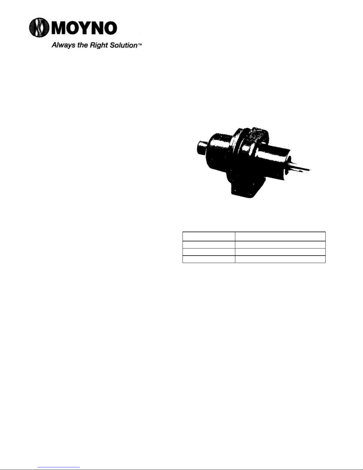
SERVICE MANUAL
MOYNO® 500 PUMPS
200 SERIES
20302, 20402, 20501, 20502, 22001, 22002, 23201, AND 23203 MODELS
DESIGN FEATURES
Housing: Stainless steel or aluminum
Pump Rotor: Phenolic & AISI 316 stainless steel
Pump Stator: NBR (Nitrile)
Shaft: AISI 316 stainless steel
Bearings: Prelubricated, fully sealed ball bearings
Seal: Mechanical (carbon/ceramic)
Note: Alternate elastomers available. Refer to
Repair/Conversion kit numbers, page 3.
Section:
MOYNO® 500 PUMPS
Page: 1 of 4
Date: December 1, 1999
INSTALLATION
Mounting Position. Pump may be mounted in any
position. When mounting vertically, it is necessary to
keep bearings above seals to prevent possible seal
leakage into bearings.
Pre-Wetting. Prior to connecting pump, wet pump
elements and mechanical seal by adding fluid to be
pumped into suction and discharge ports. Turn shaft
over several times in a clockwise direction to work fluid
into elements.
Piping. Piping to pump should be self-supporting to
avoid excessive strain on pump housings; 3/8” NPT
pipe used on 203, 204, 205 and 220 Models, and 1/2”
NPT pipe used on 232 Models. Use pipe “dope” or
tape to facilitate disassembly and to provide seal.
Drive. On belt driven units, adjust belt tension to
point of non-slip. Do not overtighten. On direct drive
units, coupling components should be aligned and
spaced at least 1/16” apart.
Pump rotation must be clockwise when facing shaft
to prevent rotor unscrewing from shaft. Check direction
of rotation before startup.
Maximum speed is 1750 rpm.
OPERATION
SeIf-Priming. With wetted pumping elements, the
pump is capable of 25 feet of suction lift when
operating at 1750 rpm with pipe size equal to port size.
Be sure suction lines are air tight or pump will not selfprime.
Note: Self-priming capabilities will vary depending on
fluid viscosity.
DO NOT RUN DRY. Unit depends on liquid pumped
for lubrication. For proper lubrication, flow rate should
be at least 10% of rated capacity at a given rpm.
Pressure and Temperature Limits. Maximum
discharge pressure is 40 psig. Unit is suitable for
service at temperatures shown in Table 1.
Storage. Always drain pump for extended storage
periods using pipe plug in pump body.
Table 1. Temperature Limits
Elastomer Temperature Limits
*NBR 10°-160°F
*EPDM 10°-210°F
*FPM 10°-240°F
*NBR = Nitrile
EPDM = Ethylene-Propylene-Diene Terpolymer
FPM = Fluoroelastomer
TROUBLE SHOOTING
WARNING: Before making adjustments, disconnect
power source and thoroughly bleed
pressure from system. Failure to do so
could result in electric shock or serious
bodily harm. Replace belt or coupling
guards before reconnecting power.
Failure To Pump.
1. Belt or coupling slip: Adjust belt tension or tighten set
screw on coupling.
2. Stator torn; possibly excessive pressure: Replace
stator. Check pressure at discharge port.
3. Wrong rotation: Rotation must be clockwise when
facing shaft.
4. Threads in rotor or on shaft stripped: Replace part.
Check for proper rotation.
5. Excessive suction lift or vacuum.
Pump Overloads.
1. Excessive discharge pressure: Check discharge
pressure for 40 psig maximum or obstruction in
discharge line.
2. Fluid viscosity too high: Limit fluid viscosity to 20,000
CP or 100,000 SSU.
3. Suction pressure should never be greater than dis-
charge pressure.

Page 2
Viscosity CP Limit RPM
1-300 1750
300-1,000 1200
1,000-2,000 700
2,000-5,000 350
5,000-10,000 180
10,000-20,000 100
4. Insufficient motor HP: Check HP requirement.
Noisy Operation.
1. Starved suction: Check fluid level, size of piping,
and obstructions in pipe.
2. Bearings worn: Replace parts.
3. Insufficient mounting: Mount securely. Reduce
vibration induced noise by using a short section of
hose on discharge piping.
Seal Leakage.
1. Leakage at startup: If leakage is slight, allow pump
to run several hours to let faces run in.
2. Persistent seal leakage: Faces may be cracked
from freezing or thermal shock. Replace seal.
Pump Will Not Prime.
1. Air leak on suction side: Check pipe connections.
PUMP DISASSEMBLY
WARNING:Before disassembling pump, disconnect
power source and thoroughly bleed
pressure from system. Failure to do so
could result in electric shock or serious
bodily harm.
1. Disconnect suction and discharge piping.
2. Remove screws (9) which secure suction housing
(2) to pump body (1). Remove suction housing (2)
and stator (3).
3. Rotor (4) is removed from shaft (5) by turning in a
counterclockwise direction (R H thread).
4. If any parts of the mechanical seal (8) are worn or
broken, the complete seal assembly should be
replaced. Seal components are matched parts and
are not interchangeable.
5. The bearings (6) and shaft (5) assembly can be
removed from the pump body (1) after the snap
ring (7) has been removed. To remove the
assembly, tap the shaft at the threaded end using
a block of wood to protect the threads. Pull slinger
ring (11) from shaft. The bearings (6) may then be
pressed off the shaft.
Note: When replacing bearings, always press on the
inner race when assembling to shaft, and on
the outer race when pressing bearings into the
housings to prevent damage to the races.
PUMP ASSEMBLY
1. Press inboard bearing on shaft using inner race.
Install slinger ring (11) on shaft. Press inboard
bearing & shaft into pump body using outer race.
Press outboard bearing on shaft and into pump
body using both races. Secure with snap ring (7).
2. Install mechanical seal (8) using the following
procedure:
a. Clean and oil sealing faces using clean light oil
(not grease).
Caution:Do not use oil on EPDM parts. Substitute
glycerin or soap and water.
b. Oil the outer surface of the seal seat, and push
the assembly into the bore in the pump body (1),
seating it firmly and squarely.
c. After cleaning and oiling the shaft, slide the seal
body along the shaft until it meets the seal seat.
d. Install seal spring and spring retainer on shaft.
3. Screw rotor (4) on shaft (5) in a clockwise direction
(R H thread).
4. Secure stator (3) and suction housing (2) to pump
body (1) with screws (9).
5. Connect suction and discharge piping and proceed
as outlined in installation instructions.
WARNING: Replace belt or coupling guards before
reconnecting power.
Item No.
Item No.
Page 3
PARTS LIST
Item
No.
Description
Pump Body
1
Suction Housing
2
Stator
*3
Rotor
*4
Drive Shaft 320-6489-000
5
Bearing (2 req.) 630-0502-021
6
Snap Ring 320-4211-000
7
Mechanical Seal 320-4215-000
*8
Screws (4 req.) 320-4787-006
9
Pipe Plug 610-0420-010
10
Slinger Ring 320-2833-008
11
*Recommended spare parts.
20302 20402 20501 20502 22001 22002 23201 23203
316 SS
330-3328-001
316 SS
330-3327-000
NBR
330-7555-120
316 SS
320-6975-000
316 SS
330-3328-001
316 SS
330-3327-000
NBR
330-7556-120
316 SS
320-7923-000
Aluminum
330-3215-001
Aluminum
330-2234-000
Phenolic
320-6485-000
619-0850-061 320-4787-006 619-0850-061 320-4787-006 619-0850-061 320-4784-006
Pump Model Numbers
316 SS
330-3328-001
316 SS
330-3327-000
NBR
330-6381-120
316 SS
320-6484-000
Aluminum
330-3215-001
Aluminum
330-2234-000
NBR
330-6382-120
Phenolic
320-6488-000
REPAIR/CONVERSION KIT NUMBERS (Not available as kit for 203, 204 Models)
Description
NBR EPDM FPM NBR EPDM FPM
- Kit No. 311-9061-000 311-9062-000 311-9063-000 311-9064-000 311-9065-000 311-9018-000
3 • Stator 330-6381-120 330-6381-320 330-6381-520 330-6382-120 330-6382-320 330-6382-520
8 • Seal 320-4215-000 320-6497-000 320-6037-000 320-4215-000 320-6497-000 320-6037-000
Description
NBR EPDM FPM
- Kit No. 311-9066-000 311-9067-000 311-9021-000
3 • Stator 330-6385-120 330-6385-320 330-6385-520
8 • Seal 320-4215-000 320-6497-000 320-6037-000
205 Models 220 Models
232 Models
NBR = Nitrile
EPDM = Ethylene Proylene Diene
FPM = Fluoroelastomer
316 SS
330-3328-001
316 SS
330-3327-000
316 SS
320-6487-000
Terpolymer
Aluminum
330-3215-000
316 SS
330-2233-000
330-6385-120
416 SS
320-6498-000
316 SS
330-3328-000
316 SS
330-3329-000
NBR
316 SS
320-6499-000

© 1999 by Moyno, Inc. Printed in U.S.A
® Moyno is a registered trademark of Moyno, Inc.
Section:
MOYNO
Page:
1
March 1, 1998
Date:
®
500 PUMPS
of 4
MOYNO
300 SERIES MOTORIZED
331, 332, 333, AND 344 MODELS
DESIGN FEATURES
Housing:
Pump Rotor:
Pump Stator:
Seal:
Motor Shaft:
Motor:
Note: Alternate elastomers available. Refer to
INSTALLATION
Mounting Position.
position. When mounting vertically, it is necessary to keep
bearings above seals to prevent possible seal leakage into
bearings.
Pre-Wetting.
and mechanical seal by adding fluid to be pumped into
suction and discharge ports. Turn pump over several times
in a clockwise direction to work fluid into pump elements.
Piping.
excessive strain on pump housings. See Table 1 for suction
and discharge port sizes of each pump model. Use pipe
“dope” or tape to facilitate disassembly and to provide seal
on pipe connections.
Electrical.
nameplate or inside the terminal box for the proper
connections. The wiring should be direct and conform to
local electrical codes. Check power connections for proper
voltage. Voltage variations must not exceed ±10% of
nameplate voltage. Motor is provided with internal
automatic overload protection.
To prevent damage to pump, pump rotation must be
clockwise when facing pump from motor end.
OPERATION
Self-Priming.
capable of 25 feet of suction lift with pipe size equal to port
size. Be sure suction lines are air tight or pump will not self
prime. Self-priming capabilities will vary due to fluid
viscosity.
DO NOT RUN DRY.
lubrication. For proper lubrication, flow rate should be at
least 10% of rated capacity.
Cast iron/316 SS
Chrome plated AISI 416 stainless steel/Chrome
plated 316 stainless steel
NBR (Nitrile)
Mechanical (carbon/ceramic)
AISI 416 stainless steel/ANSI 316 stainless
steel
1/2 HP, 60 Hertz, 1725 rpm, totally enclosed,
fan cooled (TEFC) C-Faced, 1 phase 115/230V
or 3 phase 230/460V (other motor options
available; consult sales representative)
Repair/Conversion kit numbers pages 3 and 4.
Pump may be mounted in any
Prior to connecting pump, wet pump elements
Piping to pump should be self-supporting to avoid
Follow the wiring diagram on the motor
With wetted pumping elements, the pump is
Unit depends on liquid pumped for
SERVICE MANUAL
®
500 PUMPS
Pressure and Temperature Limits.
maximum discharge pressure of each model. Unit is
suitable for service at temperatures shown in Table 2.
Storage.
by removing bottom drain plug in pump body.
Caution: Suction pressure should never be greater than
Pump
Model
†With
*NBR = Nitrile
EPDM = Ethylene-Propylene-Diene Terpolymer
FPM = Fluoroelastomer
Always drain pump for extended storage periods
discharge pressure.
Suction
Port
(NPT)
331 3/4 3/4
332 3/4 3/4
333 3/4 3/4
344 3/4 3/4
3/4
HP
motor, pressure is
Table 2. Temperature Limits
Elastomer Temperature Limits
*NBR 10°-160°F
*EPDM 10°-210°F
*FPM 10°-240°F
See Table 1 for
Table 1. Pump Data
Discharge
Port
(NPT)
Voltage
Rating
(VAC)
See Motor Name
Plate For
Voltage Ratings
See Motor Name
Plate For
Voltage Ratings
See Motor Name
Plate For
Voltage Ratings
See Motor Name
Plate For
Voltage Ratings
40
psig.
Discharge
Pressure
(psig)
150
100
50
†30

Page 2
TROUBLESHOOTING
WARNING: Before making adjustments, disconnect
power source and thoroughly bleed
pressure from system prior to
disassembly. Failure to do so could lead to
electric shock or serious bodily harm.
Failure To Pump.
1. Motor will not start: Check power supply. Voltage must
be ± 10% of nameplate rating when motor is in locked
rotor condition. Check for faulty capacitor on 1 phase
Models.
2. Motor runs and thermally kicks out: Check for
excessive discharge pressure. Check for defective
centrifugal switch on 1 phase Models. Increase
ventilation to motor. Do not use less than #14 wire size.
3. Stator torn; possible excessive pressure: Replace
stator, check pressure at discharge port.
4. Flexible joint broken; possible excessive pressure:
Replace joint, check pressure at discharge port.
5. Wrong rotation (3 phase only): Rotation must be
clockwise when facing pump from motor end. Reverse
the connections of any two line leads to the motor.
6. Excessive suction lift or vacuum.
Pump Overloads.
1. Excessive discharge pressure: Check pressure at
discharge port for maximum ratings given in Table 1.
2. Fluid viscosity too high: Limit fluid viscosity to 100 CP
or 500 SSU.
Noisy Operation.
1. Excessive suction lift or vacuum: Maximum suction lift
is 25 feet for water.
2. Suction line too small: Check pipe size. Be sure lines
are free from obstructions.
3. Pump Cavitates: Pump speed is 1725 rpm. Viscosity of
fluid should not exceed 100 CP or 500 SSU.
4. Flexible joint worn: Replace joint. Check pressure at
discharge port.
5. Insufficient mounting: Mount to be secure to a firm
base. Vibration induced noise can be reduced by using
mount pads and short sections of hose on suction and
discharge ports.
Seal Leakage.
1. Leakage at startup: If leakage is slight, allow pump to
run several hours to let faces run in.
2. Persistent seal leakage: Faces may be cracked from
freezing or thermal shock. Replace seal.
Pump Will Not Prime.
1. Air leak on suction side: Check pipe connections.
PUMP DISASSEMBLY
WARNING: Before disassembling pump, disconnect
power source and thoroughly bleed
pressure from system. Failure to do so
could result in electric shock or serious
bodily harm.
1. Remove suction and discharge piping. Drain pump
body by removing drain plug (261B).
2. Remove screws (112) holding suction housing (2) to
discharge housing (1). Remove suction housing (2) and
stator (21).
3. Remove rotor (22) from flexible joint (24) by turning
counterclockwise (RH thread). On pinned, 3 phase
models, remove rotor pin (45) with suitable punch.
4. Flexible joint (24) can be removed from motor shaft by
using a 3/16 allen wrench in end of joint and turning
counterclockwise. On 3 phase motors, remove motor
pin (46) with suitable punch, then remove joint:
5. Slide mechanical seal (69) off motor shaft.
6. Remove discharge housing (1) from adaptor flange (12)
by removing screws (1 12B).
7. Carefully pry seal seat out of discharge housing (1). If
any parts of mechanical seal are worn or broken, the
complete seal assembly should be replaced. Seal
components are matched parts and are not
interchangeable.
8. Remove adapter flange (12) from motor (70) by
removing screws (112A).
9. Remove slinger ring (77).
PUMP ASSEMBLY
1. Install slinger ring (77).
2. Attach adaptor flange (12) to motor housing using
screws (112A).
3. Attach discharge housing (1) to adaptor flange (12)
using screws (1128). Be sure to center seal bore on
shaft.
4. Install mechanical seal (69) in discharge housing (1)
using the following procedure:
a. Clean and oil sealing faces using clean oil (not
grease).
Caution: Do not use oil on EPDM parts. Substitute
glycerin or soap and water.
b. Oil outer surfaces of the seal seat, and push
assembly over the motor shaft and into the discharge
housing (1) seating it firmly and squarely.
c. After cleaning and oiling the shaft, slide the seal
body along the motor shaft until it meets the seal
seat.
d. Install seal spring and spring retainer on shaft.
5. Thread flexible joint (24) into motor shaft in a clockwise
direction (RH thread). Tighten with 3/16 allen wrench.
On 3 phase models, install motor pin (46).
6. Thread rotor (22) onto flexible joint (24) in a clockwise
direction (RH thread). On 3 phase models, install rotor
pin (45).
7. Slide stator (21) on rotor (22). On 331 & 332 models,
insert rounded end of stator ring (135) into end of stator
prior to installing stator on rotor.
8. Secure stator (21) and suction housing (2) to discharge
housing (1) using screws (112).
9. Lubricate rotor and stator by filling Suction housing and
discharge housing with fluid to be pumped.
10. Connect Suction and discharge piping and power
source.
Page 3
PARTS LIST
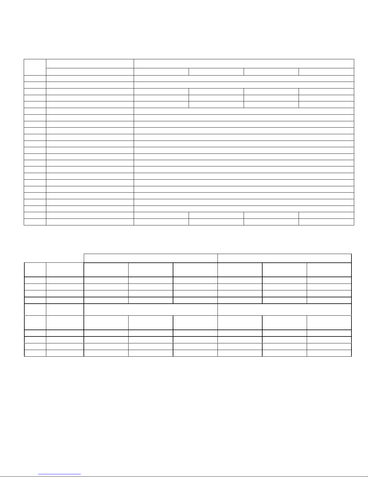
To determine part numbers for all parts except standard motors, enter table with item number from pump illustration. Then locate
part number under applicable model number (first three digits). Parts listed down the center are applicable to all pump models.
To determine part numbers for standard motor (item 70), enter table at item 70 with the last two digits of model number:
motor description and part number are on that line.
Pump Model NumbersItem
No.
*21 Stator 340-3501-120 340-3502-120 340-3503-120 340-3504-120
*22 Rotor (Threaded) 416 S5 320-2729-000 330-0906-000 320-1394-000 320-1841-000
*22 Rotor (Pinned) 416 SS 320-2729-004 320-4559-004 320-1584-002 320-1569-002
240 Flexible Joint (Pinned)
*45 Shaft Pin (2 req.)
*69 Mechanical Seal
112 Screw, Cap (8 req.)
112A Screw, Hex Hd (4 req.)
135 Stator Ring
215 Lock Washer (8 req.)
215A Lock Washer (4 req.)
261 Pipe Plug, 1/4 NPT
*
Recommended spare
Used on 3 phase models.
Description
1 Discharge Housing
2 Suction Housing
24 Flexible Joint (Threaded)
70 Standard Motor
-59 1PH TEFC 1750 RPM
-60 3PH TEFC 1750 RPM, Pin
-52 1PH TEFC 1750 RPM 330-4529-1 00
-50 3PH TEFC 1750 RPM
77 Slinger Ring
Rotor (Threaded) 316 SS 320-2933-000 320-2942-000 320-2936-000 320-2934-000
Rotor (Pinned) 316 SS 320-2933-002
parts.
331 332 333
Cast Iron 350-1016-000/Stainless Steel 350-1016-007
Cast Iron 330-1064-002/Stainless Steel 330-1911-002
Carbon Steel 320-1511-000/Stainless Steel 320-3759-000
Carbon Steel 320-1612-000/Stainless Steel 320-4415-000
320-4069-002
320-2424-000
330-4529-000
330-4528-100
330-4528-003
320-6382-000
Carbon Steel 619-1430-103 (10-24 x 5/8)/Stainless Steel 619-1432-120 (10-24 x 3/4)
Carbon Steel 619-1530-161 (3/8-16 x 1)/Stainless Steel 320-6715-005 (3/8-16 x 1)
Carbon Steel 320-7812-000 /Stainless Steel 362-1774-000
320-6464-000
Carbon Steel 623-0010-411/Stainless Steel 320-6717-002
Carbon Steel 610-0120-021/Stainless Steel 610-0420-020
344
REPAIR/CONVERSION KIT NUMBERS
All 331 Models (Threaded Only) All 332 Models (Threaded Only)
Item
No. Description NBR EPDM FPM NBR EPDM FPM
— Kit No. 311-9026-000 311-9025-000 311-9054-000 311-9027-000 311-9038-000 311-9055-000
21 • Stator 340-3501-120 340-3501-320 340-3501-520 340-3502-120 340-3502-320 340-3502-520
24 • Joint *320-1511-000 320-6367-000 320-4670-000 *320-1511-000 320-6367-000 320-4670-000
69 • Seal 320-2424-000 320-6379-000 320-6501-000 320-2424-000 320-6379-000 320-6501-000
All 333 Models (Threaded Only) All 344 Models (Threaded Only)
Item
No.
Description NBR EPDM
— Kit No. 311-9029-000 311-9028-000 311-9056-000 311-9031-000 311-9030-000 311-9057-000
21 • Stator 340-3503-120 340-3503-320 340-3503-520 340-3504-120 340-3504-320 340-3504-520
24 • Joint *320-1511-000 320-6367-000 320-4670-000 *320-1511-000 320-6367-000 320-4670-000
69 • Seal 320-2424-000 320-6379-000 320-6501-000 320-2424-000 320-6379-000 320-6501-000
NBR =
EPDM =
FPM = Fluoroelastomer
*Carbon steel joint, for 316 SS joint use 320-3759-000.
Nitrile
Ethylene-Propylene-Diene Terpolymer
FPM
NBR EPDM FPM
Page 4
REPAIR/CONVERSION KIT NUMBERS (CONT.)
All 331 Models (Pinned Only) All 332 Models (Pinned Only)
Item
No.
Description
–Kit No.
Stator
21
24
69
45
•
Joint
•
Seal
•
Pin (2 req.)
•
Item
No.
21
24
69
45
–
Description
• Kit No.
• Stator
• Joint
• Seal
Pin (2 req.)
ABRASION RESISTANT SEALS
Elastomer
NBR
EPDM
FPM
NBR EPDM FPM NBR EPDM FPM
311-9104-000 311-9108-000 311-9112-000 311-9105-000 311-9109-000 311-9113-000
340-3501-120 340-3501-320 340-3501-520 340-3502-120 340-3502-320 340-3502-520
*320-1612-000 320-6973-000 320-6984-000
320-2424.000 320-6379-000 320-6501-000 320-2424-000 320-6379-000 320-6501-000
320-4069-002 320-4069-002
All 333 Models (Pinned Only) All 344 Models (Pinned Only)
NBR EPDM FPM NBR EPDM FPM
311-9106-000 311-9110-000 311-9114-000 311-9107-000 311-9111~000 311-9115-000
340-3503-120 340-3503-320 340-3503-520 340-3504-120 340-3504-320 340-3504-520
*320-1612-000 320-6973-000 320-6984-000
320-2424-000 320-6379-000 320-6501-000 320-2424-000 320-6379-000 320-6501-000
320-4069-002 320-4069-002
All 331 – 334 Models
320-6460-000
320-6502-000
EPDM = Ethylene-Propylene-Diene Terpolymer
FPM = Fluoroelastomer
*Carbon steel joint, for 316 SS joint use 320-4415-000.
320-6503-000
320-1612-000
*
320-1612-000
*
NBR = Nitrile
320-6973-000 320-6984-000
320-6973-000 320-6984-000
ABRASION RESISTANT
SEALS
© 1999 by Moyno, Inc.
® Moyno is a registered trademark of Moyno, Inc. Printed in U.S.A.
 Loading...