

moyno 2000 CC Service Manual
Moyno
2000 CC Pumps
fCover Page

Table of Contents
PAGE
1-1. INTRODUCTION .................................................................................................................................................1
1-2. General.................................................................................................................................................. 1
1-3. Scope ....................................................................................................................................................1
1-4. Nameplate Data..................................................................................................................................... 1
1-5. Pump Rotation....................................................................................................................................... 1
1-6. Model Number ....................................................................................................................................... 1
2-1. INSTALLATION ...................................................................................................................................................2
2-2. General.................................................................................................................................................. 2
2-3. Piping..................................................................................................................................................... 2
2-4. Foundation............................................................................................................................................. 2
3-1. OPERATION ........................................................................................................................................ 2
3-2. Initial Check ........................................................................................................................................... 2
3-3. Start-up..................................................................................................................................................2
3-4. Packing Leakage ................................................................................................................................... 2
4-1. MAINTENANCE...................................................................................................................................................2
4-2. General.................................................................................................................................................. 2
4-3. Packing Adjustment ............................................................................................................................... 2
4-4. Packing Replacement............................................................................................................................ 3
5-1. DISASSEMBLY.................................................................................................................................................... 3
5-2. Disconnect Pump................................................................................................................................... 3
5-3. Stator Removal...................................................................................................................................... 3
5-4. Suction Housing Removal ..................................................................................................................... 3
5-5. Rotor/Con Rod/Drive Shaft Assembly Removal ....................................................................................3
5-6. Packing Housing Removal...................................................................................................................... 4
5-7. Seal Housing Removal ........................................................................................................................... 4
5-8. Rotor, Driveshaft, and Connecting Rod Disassembly ............................................................................. 4
5-9. Drive Adapter/Gearmotor Removal
5-10. Cleaning ............................................................................................................................................... 4
6-1. INSPECTION........................................................................................................................................................ 4
6-2. Drive Shaft and Packing/Seals .............................................................................................................. 4
6-3. Rotor...................................................................................................................................................... 4
6-4. Stator ..................................................................................................................................................... 4
6-5. All Other Parts ....................................................................................................................................... 4
7-1. ASSEMBLY.......................................................................................................................................................... 5
7-2. Lubrication During Assembly ................................................................................................................. 5
7-3. Driveshaft and Rotor Gear Joint Assembly............................................................................................ 5
7-4. Drive Adapter Assembly ........................................................................................................................ 5
7-5. Pumps with Single Mechanical Seal ...................................................................................................... 5
7-6. Pumps with Compression Packing ........................................................................................................6
7-7. Pumps with Double or Cartridge Mechanical Seals............................................................................... 6
7-8. Suction Housing/Stator Assembly.......................................................................................................... 6
7-9. Pump Connections.............................................................................................................................................. 6
8-1. STORAGE ........................................................................................................................................................... 6
9-1. RECOMMENDED SPARE PARTS ...................................................................................................................... 6
10-1. HARDWARE LIST – BB022 thru BA175............................................................................................................ 7
10-2. HARDWARE LIST – BA220 thru BC345............................................................................................................ 8
11-1. PARTS LIST – BB022 thru BA175..................................................................................................................... 9
11-2. PARTS LIST – BA220 thru BC345................................................................................................................... 10
12-1. EXPLODED VIEW ........................................................................................................................................... 11
13-1. SEAL SET DIMENSIONS ................................................................................................................................ 12
14-1 TROUBLESHOOTING CHART........................................................................................................................ 13
........................................................................................................ 4

SERVICE MANUAL
Moyno2000 CC Pumps
-1. INTRODUCTION
1
1-2. General
The Moyno 2000 pump is a progressing cavity pump. A single
helical rotor rolling eccentrically in the double-threaded helix of
the stator creates the pumping action. In its revolution, the rotor
forms, in conjunction with the stator, a series of sealed cavities
180 degrees apart. As the rotor turns, the cavities progress
from the suction to the discharge. As one cavity diminishes, the
opposing cavity increases at exactly the same rate. Thus, the
um of the two discharges is a constant vos
pulsationless,
positive displacement flow.
1-3. Scope
This service manual covers the installation and maintenance
requirements for standard, close-coupled configuration of the
oyno 2000 pump line. DisassemM
are also covered in this manual.
bly and assembly procedures
1-4. Nameplate Data
The pump nameplate, located on the drive adapter, contains
important information relative to the operation and servicing of
he pump. This information includes the directt
arrow and the pump model and serial numbers.
he model and seriT
ordering spare parts.
1-5. Pump Rotation
A rotation arrow on the nameplate indicates the direction of
otation. Standard rotation of Moyno 2000 pumr
when viewed from the dr
1-6. Model Number
The pump model number is a series of numbers and letters,
which identifies the pump’s basic design and materials of
construction. A typical model number, for example, might be
BB01
65CD
1
-1.
Q3SA1AAAC, as shown on the nameplate in Figure
MOYNO
PROGRESSING
MODEL NO. 1BB065CDQ3SA1AAAC
MFG. SERIAL AS1234504
DO NOT START OR RUN PUMP WHEN DRY
al numbers must be used when
iven end of the pump.
CAVITY PUMPS
ROTATION →→→
lume. The result is a
ion of rotation
ps is clockwise,
U.S.A.
Section:
MOYNO 2000 PUMPS
Page: 1
Date: March 2010
Figure 1-1. Typical nameplate showing rotation arrow,
odel, and mam nufacturing serial numbers.
The first six numbers and letters identify the pump’s basic design
haracteristics. c
In the first space, a number identifies the number of stages in the
umping elements. This wp
The second position, the letter “B”, designates the pump type as
eing close-coupled. b
In the thir (con
rod/gear j
The next three positions, always numbers, identify the pumping
The next 3 positions, always letters, describe the pump’s “materials
The first letter in this group identifies the material of the suction
housing casting.
The second letter indicates the material used in the rotating parts,
i.e., the drive shaft, con rod, rotor, and other metallic parts in
contact with the material being pumped.
The third letter indicates the material of the stator. It identifies only
the stator material and not that of the tube in which the stator is
The s
would
The next position is a number identifying the current pump revision.
This manual corresponds to Revision 3.
first letter identifies whether packing, a single seal, or
o king model and type used.
A ing:
d position, a letter designates the pump’s drive train
oint/drive shaft):
A – One size smaller than element (175/220 onl
B – Same size as element
C – Same size as element, but larger gearbox drive
flange and drive shaft size (175/220/345 only)
ement in terms of theoretical gallons per 100 el
f construction” ino
aced. The tube, a non-wetted ppl
tandard designation such as the CDQ used in our example
result in the following:
C = Cast iron suction chamber
D = Hardened alloy steel internals including drive shaft, con
Q = Nitrile (NBR) stator (70 durom
he next three letters indicate theT
being used. The second and third positions indicate specific seais
r pac
typical trim code is SA1, designating the follow
S = Single mechanical seal
A1 = John Crane type 2100 SiC/SiC/Viton/316
component groups of parts.
rod, gear joint, and rotor
ill generally be a 1 or 2.
y)
revolutions.
art, is always alloy steel.
eter hardness)
sealing system of the pump. The
a double seal
l
1
The next letter indicates whether there are any special options
being used in the pump, typically this is an A for no special
options.
The next letter indicates the suction configuration. For this
pump an A is used designating a standard flanged pump.
The last letter indicates the drive configuration and
flange/shaft/seal size. In our close coupled pump nameplate
the C designates a 250mm flange and 45mm shaft.
2-1. INSTALLATION
2-2. General
Accessibility to the pump and adequate clearance should be
prime considerations in any installation. Enough space should
surround the unit so that maintenance can be performed with
ease.
2-3. Piping
1. Suction piping should be as short as possible. Normally,
the suction line should be the same diameter as the pump
suction; however, conditions such as high viscosity or
required minimum flow velocities may dictate otherwise.
Long-sweep 90-degree elbows or 45-degree elbows
should be used instead of the standard elbow. Avoid using
suction piping loops, which trap air.
2. Discharge piping diameter should generally be as large as
the discharge port unless fluid conditions indicate
otherwise.
3. An easily removable section of piping, at least twice as
long as the stator, should be mated to the discharge port.
This will allow the rotor and stator to be removed without
having to remove the complete pump from the base.
2-4. Foundation
For maximum pump-driver unit life, each unit should be
mounted on a strong steel baseplate. The baseplate should be
mounted on a firm foundation. The motors should be supported
on close-coupled configurations above 30 HP.
3-1. OPERATION
3-2. Initial Check
Before putting the pump into operation, the following items
should be checked to ensure that each piece of equipment is
installed correctly:
Electrical connections.
Gauges and other instruments.
Pump rotation. Rotation is indicated on the pump
nameplate.
All valves should be open on both suction and discharge
sides of pump.
Seal flush systems if required should be operational.
Double seals require flushing between faces.
CAUTION: This is a positive displacement pump. Do not
operate it against a closed valve.
3-3. Start-Up
CAUTION: DRY OPERATION IS HARMFUL TO THE PUMP!
Never allow the pump to operate without liquid, as dry
operation will cause premature wear of the stator and possible
damage. The liquid being pumped lubricates the stator.
1. Before operating the pump for the first time, fill it with liquid
to lubricate the stator for the initial start-up.
Note: If the pump is shut down temporarily, enough liquid will
remain in the system to provide lubrication upon restarting. It
is advisable to maintain the suction piping at a higher
elevation than the centerline of the pump in order to contain
some liquid in the pump at time of shutdown.
2. Once the pump has been filled with liquid, check for direction
of pump rotation by momentarily starting and stopping the
drive. See pump nameplate for correct rotation.
3. Start seal flush water if so equipped.
4. Start pump.
3-4. Packing Leakage
The packed stuffing box is designed to control leakage, not stop
it completely. Leakage is necessary to reduce friction and
dissipate heat.
In a new pump, before the packing has had a chance to seat
properly, excessive leakage through the stuffing box is common.
Frequent adjustments of the packing gland may be necessary
during the first few hours of operation in order to compress and
seat the packing. See Section 4-3.
4-1. MAINTENANCE
4-2. General
The Moyno 2000 CC pump has been designed for a minimum of
maintenance, the extent of which is routine adjustment of the
packing. The pump is one of the easiest to maintain because the
main elements are very accessible and require few tools to
disassemble.
4-3. Packing Adjustment
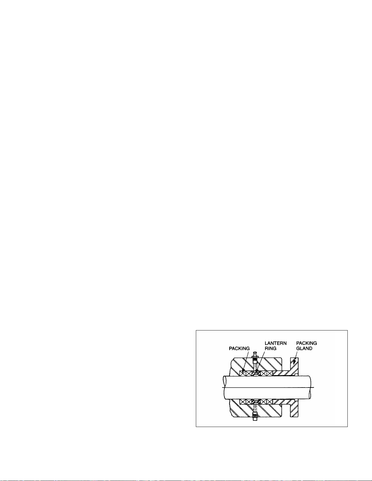
Packing gland nuts (see Figure 4-1) should be evenly adjusted.
Overtightening the packing gland may result in premature
packing failure and possible damage to the shaft and gland.
Figure 4-1. Cross Section of Packing Housing
2
he next letter indicates whether there are any special options
T
ng used in the
b is is an A for no special
options.
The next letter indicates the suction configuration. For this
pump an A is used designating a standard flanged pump.
The last letter indicates the drive configuration and
flange/shaft/seal size. In our close coupled pump nameplate
designates a 250mm flange and 45 C
the mm shaft.
pump, typically thei
2-1. INSTALLATION
-2. General 2
Accessibility to the pump and adequate clearance should be
prime considerations in any installation. Enough space should
surround the unit so that maintenance can be performed with
ease.
-3. Pip
2
ing
1. short as possible. Normally,
Suction piping should be as
the suction line should be the same dia the pump
sucti r, conditions
on; howeve such as high viscosity or
required minimum flow velocities may dictate otherwise.
weep 90-degree el
Long-s
should be used instead of th
suction piping loops, which trap air.
2. Discharge piping diameter should generally be as large as
the discharge port unless fluid conditions indicate
otherwise.
bows or 45-degree elbows
e standard elbow. Avoid using
meter as
3. An easily removable section of piping, at least twice as
long as the stator, should be mated to the discharge port.
This will allow the rotor and stator to be removed without
having to remove
the complete pump from the base.
2-4. Foundation
maximum pump-driver unit life, each unit should be
For
mounted on a strong steel baseplate. The baseplate should be
m
ounted o
on close-coupled configurations above 30 HP.
n a firm foundation. The motors should be supported
3-1. OPERATION
3-2. Initial Check
Before putting the pump into operation, the following items
should be checked to ensure that each piece of equipment is
installed correctly:
Electrical connections.
Gauges and other instruments.
Pump rotation. Rotation is indicated on the pump
nameplate.
All valves should be open on both suction and discharge
sides of pump.
eal flush systems if required should be operational.
S
Double seals require flushing between faces.
CAUTION: This is a positive displacement pump. Do not
operate it against a closed valve.
3-3. Start-Up
CAUTION: DRY OPERATION IS HARMFUL TO THE PUMP!
Never allow the pump to operate without liquid, as dry
operation will cause premature wear of the stator and possible
damage. The liquid being pumped lubricates the stator.
1.
Before operating the pump for the first time, fill it with liquid
to lubricate the stator
Note: If the pump is shut down
remain in the system to provide lu
is advisable to maintain the suction piping at a higher
elevation than the centerline of the pump in order to contain
some liquid in the pump at time of shutdown.
2. Once the pump has
of pump rotation by momentarily starting and stopping the
drive. See pump nameplate for correct rotation.
3. Start seal flush water if so equipped.
4. Start pump.
for the initial start-up.
temporarily, enough liquid will
brication upon restarting. It
been filled with liquid, check for direction
3
-4. Packing Leakage
The packed stuffing box is designed to control leakage, not stop
it completely. Leakage is necessary to reduce friction and
dissipate heat.
In a new pump, before the packing has had a chance to seat
properly, excessive leakage through the stuffing box is common.
Frequent adjustments of the packing gland may be necessar
during the first few hours of operation in order to compress and
seat the packing. See Section 4-3.
4-1. MAINTENANCE
4-2. General
The Moyno 2000 CC pump has been designed for a minimum o
maintenance, the extent of which is routine adjustment of the
packing. The pump is one of the easiest to maintain because the
main elements are very accessible and require few tools to
disas
semble.
4-3. Packing Adjustment
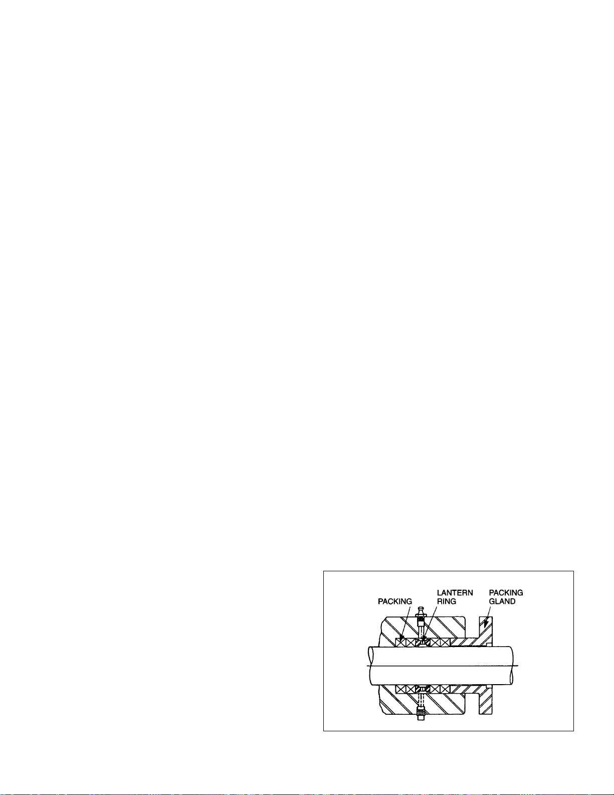
Packing gland nuts (see Figure 4-1) should be evenly adjusted.
Overtightening the packing gland may
packing failure and possible damage to the shaft and gland.
result in premature
3
y
f
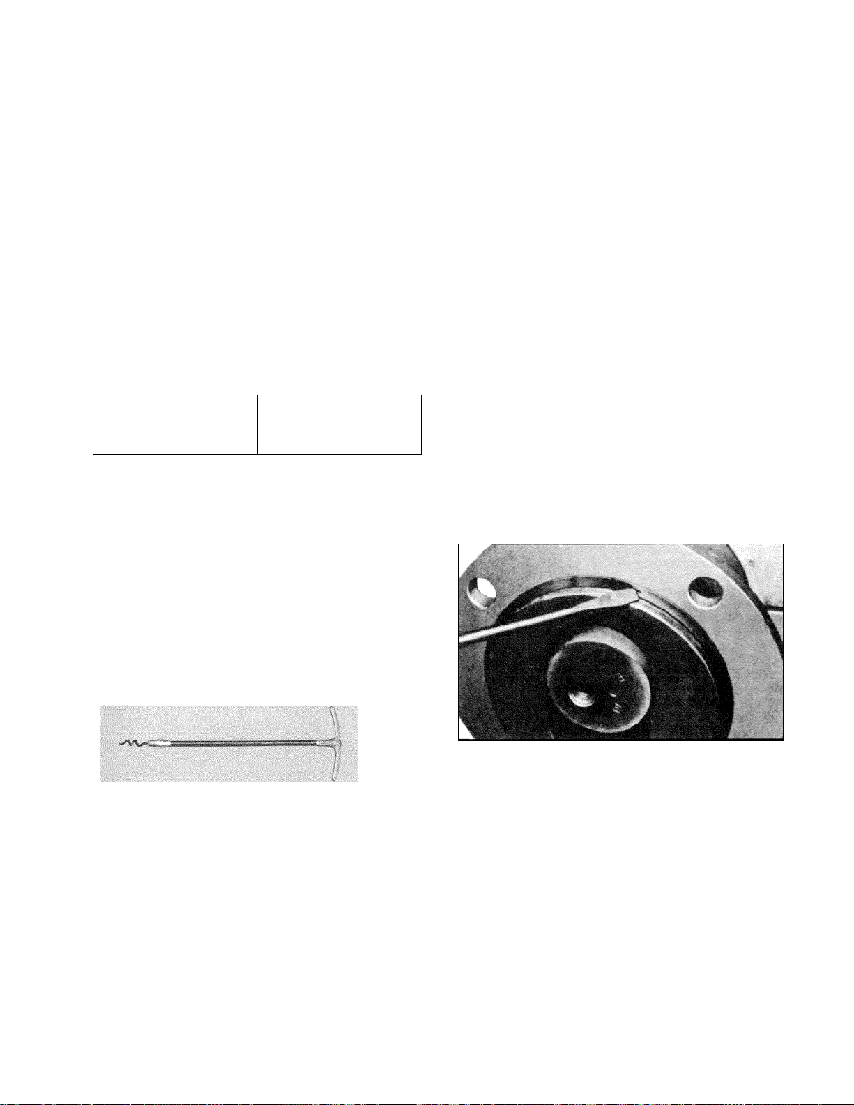
Figure 4-1. Cross Section of Packing Housing
When packing is new, frequent minor adjustments during the
first few hours of operation are recomme
compress and seat the packing.
1. Upon initial start-up
for a leakage rate of 50-100 drops per minute until the
packing has seated and adjusted to the operating
temperature (approximately 10-15 minutes).
2. If leakage is excessive after 15 minutes of operation,
tighten the gland nuts ¼ of a turn.
3. Tighten the gland nuts ¼ o
minutes if necessary and repeat this procedure until a
desired leakage of 1-2 drops per minute is obtained.
Adding grease may also
barrier at the lantern ring.
of the pump, adjust the gland nuts
f a turn after an additional 15
reduce leakage by providing a
AUTION: DoC
Overtightening the packing gland may result in accelerated
wear on the packing and damage to the shaft. In those
ituations where no packing leas
your Moyno Authorized Representative.
not tighten until zero leakage is obtained.
kage can be tolerated, consult
Area To Lubri
Packing
cate
Approved Lubricant or
(Dubois Chemical, Inc.)
4-4. Packing Replacement
Note: In this section, the first reference to each pump part will
e followed by a number or a letb ter in parentheses ( ). These
numbers and letters are used to identify the pump parts and
hardware items in the Exploded Views in Section 13-1.
When tightening the gland nuts can no longer regulate leakage,
remove and replace the packing. The entire pump does not
need to be disassembled to replace the packing. Briefly,
replace as follows:
1. Remove packing gland nuts and slide gland halves (152)
back along
2. Use a packing puller tool (see Figure 4-2) to remove the
packing (150).
drive shaft (400).
nded in order to
Equivalent
ACG-2
. ith packing gland
5 Replace packing gland halves and secure w
and nuts (156).
6. Adjust packing per Section 4-3.
5-1. DIS
Note: In this section and in following sections on CLEANING,
SPECTION, and ASSEMBLY, the first reIN
rt will be followed by a numb . These
pa er or letter in parentheses ( )
numbe are those rts and
hardwa e Exploded Vi
5-2. Disc ct Pump
1. Disconnect the power source.
2. Close suction and discharge valves to isolate the pump from
the lin
-3. Stat moval
5 or Re
1. Remove section of discharge pipe attached to discharge
flange (200).
2. Remove discharge flange by unbolting from stator clamp ring
(210) and remove stator gasket (510). Use a screwdriver tip to
remove stator retaining ring (480), stator clamp ring (210),
and pump support (220) from stator (500).
3. Unbolt stator clamp ring (210) from suction housing and
remove stator from rotor (turning stator clockwise wh
removing will ease disassembly). Remove the stator retaining
ring. Remove stator clamp ring from stator. See Figure 5-1.
for the typical retaining ring removal procedure.
ASSEMBLY
re items in th
onne
e.
ference to each pump
use p pars and letters
d to identify the pum
ews in Section 13-1.
ile
F
3. Inspect surface of drive shaft for e
4. If drive shaft is not worn, i
Note: The stuffing box is supplied with four rings installed, a
AU AYS USE A PROPER PACKING TAMPER
TOOL TO INSTALL PACKING. Do not use a pointed or sharp
tool, as damage to the packing material or drive shaft could
resul
piece
igure 4-2. Packin
grooves due to packing rub. If shaft
scored or grooved, it should be replaced.
packing rings, lubricating them before installation with a
good grade of packing grease. Be
packing ring joints at 90-degree increments.
fifth ring may be added after initial compression.
TION: ALWC
t. To assure proper shaft lubrication, never use a one-
spiral wrap packing.
g Removal Tool
xcessive wear or
is worn, or is badly
nstall a lantern ring and four
sure to stagger the
Figure 5-1. Typical Retaining Ring Removal
5-4. Suction Housing Removal
1. Remove four bolts and lock w
housing (
Pull the suction housing toward the rotor and away from the
2.
adapter housing. Place a block of wood under the suction
housing to prevent it from dropping as you pull it away from
the ad
100) to the drive adapter (10).
apter housing.
5-5. Rotor / Con Rod / Dri
1. Slide the slinger ring (60) along the drive shaft (400), towards
the gear reducer, exposing the drive pin (70).
With a punch and hammer, tap the drive pin fr2.
shaft.
ashers (230) holding the suction
ve Shaft Assembly Removal
om the drive
4
 Loading...