

moyno 2000 Service Manual

SERVICE MANUAL
MOYNO
2000 Pumps
G2/G3 Enhanced Feed Models
Version 5 Models
®

TABLE OF CONTENTS
1-1. INTRODUCTION……………………………….....
Page
1
1-2. GENERAL………………………………… 1
1-3. NAMEPLATE DATA……………………... 1
1-4. Pump Rotation………………… 1
1-5. Model Number………………… 1
1-6. Frame Size Designation……… 1
1-7. Type Designation……………... 1
1-8. Version Designation………….. 2
1-9. Trim Code……………………... 2
1-10. Variation of Standard Parts….. 2
2-1. INSTALLATION…………………………………… 2
2-2. GENERAL………………………………… 2
2-3. PIPING……………………………………. 2
2-4. Suction Piping…………………. 2
2-5. Discharge Piping……………… 2
2-6. FOUNDATION…………………………… 2
2-7. SHAFT ALIGNMENT……………………. 3
2-8. On Coupling Connected Units. 3
2-9. On Belt Drive Units…………… 3
2-10. WATER FLUSH OF PACKING……….. 3
3-1. OPERATION…………………………………….... 3
3-2. INITIAL CHECK………………………….. 3
3-3. START-UP……………………………….. 3
3-4. PACKING LEAKAGE……………………. 4
4-1. MAINTENANCE…………………………………… 4
4-2. GENERAL………………………………… 4
4-3. PACKING ADJUSTMENT………………. 4
4-4. PACKING REPLACEMENT…………….. 4
4-5. LUBRICATION…………………………… 5
4-6. Bearings………………………...5
4-7. Gear Joints…………………….. 5
4-8. PUMP DISASSEMBLY……………..…... 5
4-9. Disconnect Pump……………... 5
4-10. Packing Removal……………... 5
4-11. Stator Removal……………….. 5
4-12. Drive train removal………..….. 5
4-13. Rotor, Connecting Rod, and
Intermediate Shaft Removal .. 6
4-14. Drive Shaft and Bearings
Removal……………………….. 6
4-15. G3 BRIDGE BREAKER
DISASSEMBLY………………………… 6
4-16. G3 Paddle Removal………..… 6
4-17. G3 Bearing Side Removal..….. 6
4-18. G3 Drive Side Removal……… 6
Page
4-19. CLEANING…………………………….. 7
4-20. INSPECTION………………………….. 7
4-21. Bearings…………………..….. 7
4-22. Drive shafts………………..…. 7
4-23. Seals……….……………..….. 7
4-24. Packing…….……………….... 7
4-25. Rotor…….………………..….. 7
4-26. Stator…….………………..….. 8
4-27. All Other Parts……………….. 8
4-28. PUMP ASSEMBLY …………………… 8
4-29. Lubrication During Assembly. 8
4-30. Packing Installation…………. 8
4-31. Bearing Housing/Suction
Housing Assembly…………... 8
4-32. Bearing/Drive Shaft
Assembly……………………... 8
4-33. Rotor/Stator Assembly……… 9
4-34. Rotor Gear Joint Assembly… 9
4-35. Rotor/Stator to Drive End
Assembly……………………... 10
4-36. Stator Support/Discharge
Assembly…………………….. 10
4-37. G3 BRIDGE BREAKER ASSEMBLY . 11
4-38. G3 Drive Side Assembly……. 11
4-39. G3 Bearing Side Assembly … 11
4-40. G3 Paddle Assembly …….…. 11
4-41. FINAL ASSEMBLY……………………. 12
4-42. Packing Adjustment……..…. 12
4-43. OTHER CONSIDERATIONS………… 12
4-44. Short Term Storage .………. 12
4-44. Long Term Storage .………. 12
4-46. PACKING SPECIFICATION…………. 12
4-47. VARIATIONS OF STANDARD PARTS.
12
4-48. Rotors……..…………….……. 13
4-49. Drive Shafts……………...….. 13
4-50. PUMP MODEL DESIGNATION…..… 13
4-51. G2 PARTS LISTS………………….…. 14
4-52. Table 4.1 G2 Exploded View 15
4-53. G3 PARTS LISTS………………….…. 16
4-54. Table 4.2 G3 Exploded View.17
4-55. TROUBLESHOOTING CHART…..…. 18
Note: This service manual outlines installation, operation and maintenance procedures for the flanged ”G4” models of Moyno 2000
pump. For information on the flanged G1, open throat (G2) and/or the bridge breaker (G3) models of the Moyno 2000 pump,
refer to their respective Service Manual, or contact your nearest Moyno pump representative.

Section: MOYNO® 2000 G2/G3 PUMPS
Page: 1
Date: October 2005
SERVICE MANUAL
®
Moyno
2000 Pumps
G2/G3 Enhanced Feed Open Throat Models
1-1. INTRODUCTION
1-2. GENERAL
The Moyno® 2000 Pump is the culmination of over 70 years of
experience in manufacturing and marketing fluids handling
equipment. This rugged pump has been engineered to be the most
reliable product ever sold under the Moyno name. The pump has
been painstakingly tested to assure consistent performance in the
most difficult of applications. It represents the next generation of the
world’s most versatile pump.
The Moyno 2000 Pump is a progressing cavity pump. A single
helical rotor rolling eccentrically in the double helix of the stator
creates the pumping action. The rotor in conjunction with the stator
forms a series of sealed cavities 180 degrees apart. s the rotor
turns, the cavities progress from the suction to the discharge. As
one cavity diminishes, the opposing cavity increases at exactly the
same rate. Thus the sum of the two discharges is a constant
volume. The result is a pulsation-free positive displacement flow
utilizing no valves.
The G2 product line is the latest Moyno design which incorporates a
wide open throat feed hopper with auger connecting rod for better
fill efficiency. The G3 version incorporates the features of the G2
open throat plus has a separate bridge breaker mechanism to
effectively pump even higher solids and viscosity products. This
manual supports the G2/G3 version 5 product lines purchased after
Oct 2003 (See fig 1-1 for indicator in trim code).
G2 Version 5 features include integral extension tube, larger auger
feed connecting rods, and two piece drive shaft for easy
maintenance. The G3 Version 5 includes the features of the G2 plus
separate drive on the Bridge Breaker to allow the flexibility to vary
the paddle speed, separate from the pump, when needed. The
paddle shaft is designed for maintenance ease by allowing the
paddles to be removed from the inside of the suction hopper. This
feature allows servicing of the bottom pump portion without
disturbing the bridge breaker drive mechanism, significantly
reducing downtime.
1-3. NAMEPLATE DATA
The pump nameplate, located on the bearing housing, contains
important information relating to the operation and servicing of the
pump. This information includes the direction of rotation arrow and
the pump model and serial numbers (see Figure 1-1.). The pump
model number must be used for reference when ordering spare
parts.
1-4. Pump Rotation. A rotation arrow on the nameplate indicates
the direction of rotation. Normal rotation of Moyno 2000 pumps is
clockwise, when viewed from the driven end of the pump.
Figure 1-1. Typical nameplate showin g rotation arrow,
model, and manufacturing serial numbers.
1-5. Model Number. The pump model number consists of
three component parts: Frame Designation, Type Designation
and a Trim Code. A typical model number, for example, might
be 2G036G2M20 CDQ 5AAA, as shown on the nameplate in
Figure 1-1. Version #5 is indicated before the trim code (IE:
5AAA).
1-6. Frame Designation. The Moyno 2000 is modular in
concept allowing for optimal matching of drive ends and pump
elements (rotor and stator) to meet the requirements of the
application. The ten or more characters in the frame
designation describe the particular combination of drive end,
hopper length, and pump elements, as well as other
construction details of your pump. The first character in the
frame designation, always a number, indicates the number of
stages of the pump elements.
The second character is always a letter (E-K) and indicates
the drive end size. The third, fourth and fifth numerical
characters are indicating the theoretical capability of
pumping elements per 100 revolutions on water. The sixth
character represents the type of universal joint utilized, “G” =
gear type joint. The seventh character, a number, indicates
the type of suction housing. Open throat pumps are
designated by a “2”, open throat pumps with a bridge breaker
option by the numeral “3”. On the G2 and G3 versions, the
eighth character is a letter that represents the type of hopper
and auger style used. The length of the hopper is designated
by the ninth and tenth numerical characters. A length
designation of 20 indicates a hopper length made to mate to 2
meter belt filter press (2.2 meters wide).
1-7. Type Designation. Following the Frame Designation is
the Type Designation, a series of three letters describing the
materials from which the pump is constructed.
the
1
The first letter identifies the material of the suction housing.
C ⎯ Cast Iron
E ⎯ Carpenter 20 Stainless Steel*
G ⎯ 416 Stainless Steel
H ⎯ Hastelloy “C”**
J ⎯ 17-4 pH Stainless Steel
M ⎯ Monel***
S ⎯ 316 Stainless Steel
W ⎯ Cast Steel
X ⎯ Special to Application
The second letter indicates the material used in the drive shaft,
connecting rod, rotor, and other wettable parts.
D ⎯ Alloy Steel
E ⎯ Carpenter 20 Stainless Steel*
G ⎯ 416 Stainless Steel
H ⎯ Hastelloy “C”**
J ⎯ 17-4 pH Stainless Steel
M ⎯ Monel***
S ⎯ 316 Stainless Steel
X ⎯ Special to Application
The third letter indicates the material of the stator. It identifies
only the stator material and not that of the tube. The stator tube
construction is typically carbon steel since it is isolated from the
pumpage. Standard stator materials used in the Moyno 2000
pump are as follows:
B ⎯ EPDM 300, 70 Durometer
C ⎯ Nitrile 103, 50 Durometer
D ⎯ Tool Steel
E ⎯ Nitrile 110, 70 Durometer
F ⎯ Fluoroelastomer 500, 75 Durometer
G ⎯ 416 Stainless Steel
H ⎯ Hastelloy “C”**
I ⎯ Teflon 15% Glass†
J ⎯ 17-4 pH Stainless Steel
K ⎯ Hypalon 800, 70 Durometer†
M ⎯ Nitrile 100M 70 Durometer
P ⎯ Thiokol 70 Durometer‡
Q ⎯ Nitrile 100, 70 Durometer
R ⎯ Natural Rubber 200, 55 Durometer
T — Teflon 15% glass
U ⎯ Urethane 70 Durometer
X ⎯ Special to Application
Z ⎯ White Nitrile 150, 70 Durometer
A typical type designation, such as CDQ, would identify the
following materials of construction:
C ⎯ Cast iron suction housing
D ⎯ Alloy steel rotor, drive shaft, connecting rod and
other minor metallic parts in contact with the fluid being
pumped.
Q ⎯ Nitrile (70 Durometer) stator
*Carpenter 20 is a trademark of Carpenter Technology Corp.
**Hastelloy is a trademark of Cabot Corp.
***Monel is a trademark of INCO Alloy Corp.
†Hypalon and Teflon are trademarks of E. I. DuPont de Nemours
and Company
‡Thiokol is a trademark of Morton Thiokol, Inc.
1-8. Version Designation. Following the Frame Designation is
the a number which indicates the version Designation. A metric
version sold into the world markets is designated as a 1. The
current ANSI version, covered in this service manual, is
designated by 5.
1-9. Trim Code. Also included in the Model Number is the
three character Trim Code which is used to identify pump
construction. The letters “AAA” signify standard construction,
with letters other than “A” signifying variations. The first letter
identifies sealing variations; the second, internal variations;
and the third, rotor variations.
1-10. Variations of Standard Parts. Refer to Sections 4-47
through 4-49 for variations available for modifying pumps to
meet specialized pumping conditions. If the trim code of your
pump is other than “AAA”, contact your nearest Moyno
representative for clarification. Do not modify your pump with
any variation unless you have determined that it is compatible
with your application.
2-1. INSTALLATION
2-2. GENERAL
Moyno pumps are lubricated and tested at the factory prior to
shipment and require minimum pre-start up maintenance.
Packing, however, is not lubricated at the factory.
Accessibility to the pump and adequate clearance should be a
prime consideration in any installation. Enough space should
surround the unit so that maintenance can be carried out with
ease.
2-3. PIPING
2-4. Suction Hopper used with open throat and bridge breaker
pumps should have nearly vertical sides, or be otherwise
designed to enhance the flow of the material into the pump.
2-5. Discharge Piping diameter should generally be as large
as the pump ports unless fluid conditions indicate otherwise.
An easily removable section of piping one-to-two times longer
than the connecting rod (approximately the length of the
suction housing and bearing housing together) should be
mated to the discharge port. This will allow the rotor and stator
to be removed without having to remove the complete pump
from the base.
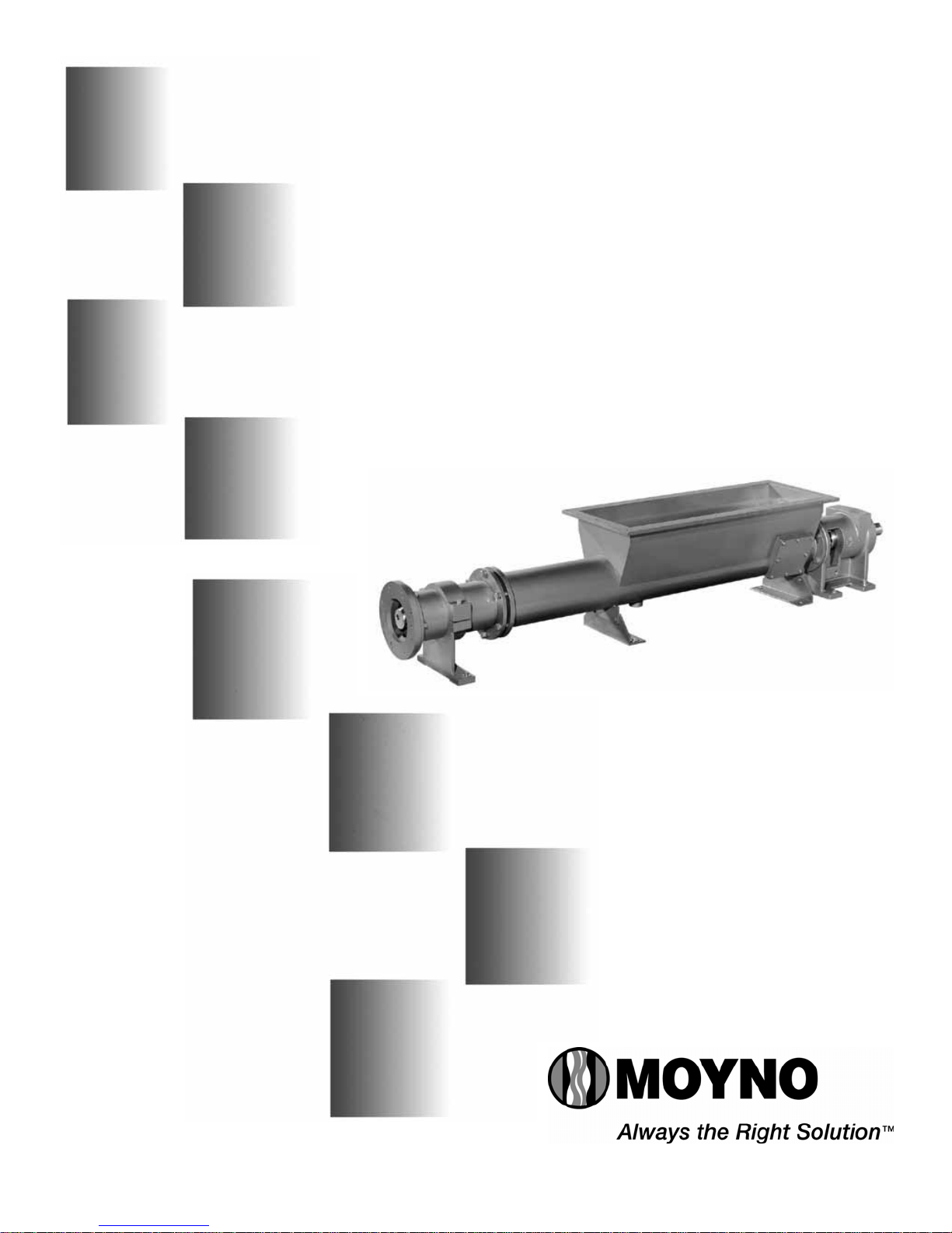
2-6. FOUNDATION
Each unit should be mounted on a strong, fabricated steel base
plate. The base plate should be mounted on a concrete
foundation. The foundation should be approximately 4” to 8”
longer and wider than the base for which it is built (See Figure
2-1.). Anchor bolts for the base plate should be located in the
foundation.
Figure 2-1. Typical Foundation Example
2
Check the base plate surface with a carpenter’s level and
place shims under the base plate at the places necessary to
make it level. Then check the pump driver shaft and the
pump ports to ensure that they are level. Complete base
mounted units supplied by Moyno including pump and driver
are leveled with respect to the base at the factory. Shifting
may occur during shipment. The pump and driver should be
realigned. Care should be exercised to ensure that all
components are level and mounted in a direct line.
For maximum rigidity and lower noise levels, the base plate
should be grouted to the foundation after the anchor bolts have
been evenly tightened. A good grade of non-shrink grout is
recommended. The spaces between the base plate and the
foundation around the shims should also be filled with grout.
Allow the grout to dry according to manufacturers’ instructions,
then fully tighten the anchor bolts.
2-7. SHAFT ALIGNMENT
Although the base-mounted units supplied by Moyno are
leveled with respect to the base before shipment, most of the
larger pump and driver units are shipped with the flexible
coupling disconnected.
After the base has been bolted down to the foundation, check
the following conditions:
2-8. On Coupling Connected Units, be sure that the pump
and driver shafts are realigned before the coupling is
connected. Care should be exercised to ensure that all
components are level and mounted in a direct line.
Check gap between coupling halves (refer to coupling
manufacturer’s recommendations). Adjustment can usually be
accomplished by loosening the mounting bolts on either the
pump or driver and moving the loosened component into
alignment with the fixed component. On couplings with equal
diameter hubs, it may be possible to lay a straight edge axially
across the coupling halves to check alignment.
Check gear reducer and motors for proper lubrication per
manufacturer’s recommendations.
2-9 On Belt Drive Units, check to ensure that sheaves or
sprockets are in alignment. Check belts for proper tension.
Tension requirements will vary with type of belt, center
distances, and belt speeds. Consult belt manufacturer for
specific recommendation.
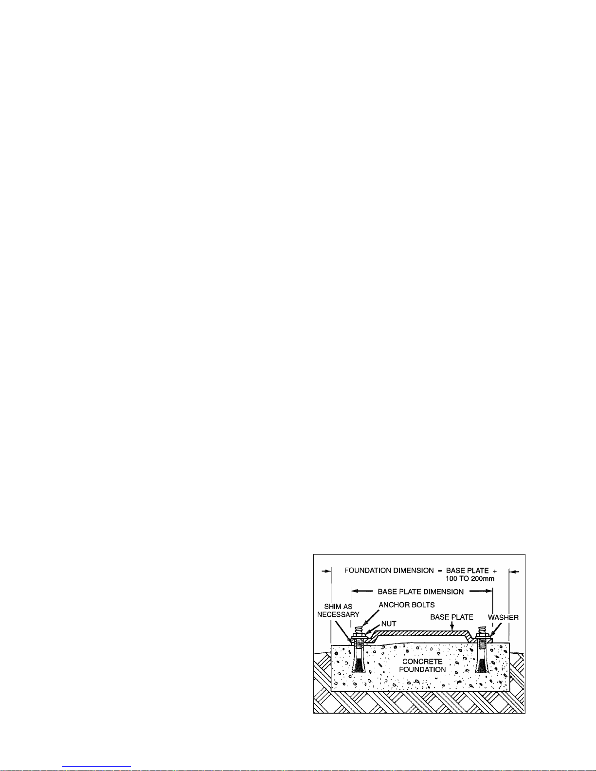
2-10. WATER FLUSH OF PACKING
The packing may be either grease lubricated through a grease
fitting in the stuffing box or have plumbing connected to the
housing to allow for water flushing.
Packing is not grease lubricated at the factory prior to
shipping.
When the material being pumped is abrasive, water flushing
the packing is recommended to extend shaft life.
Clean water can be injected through a 1/8” NPT hole that
normally houses the grease fitting for lubricating the packing.
The water should be permitted to leak axially along the shaft
and be removed from the second tapped hole in the stuffing
box. The discharge from the stuffing box should be throttled
slightly to maintain 10 – 15 PSI higher pressure in the stuffing
box than is present in the suction housing (See Figure 2-2.).
Flow rate should be approximately ½ - 2 GPM.
If a mechanical seal is used, consult the seal manufacturer’s
instructions for seal flush requirements.
Figure 2-2. Typical water flush arrangement for units w ith
packing includes strainer valve (1), pressure regulating
valve (2), sight flow meter (3), solenoid valve (4), pressure
gauge (5), and needle valve (6).
3-1. OPERATION
3-2. INITIAL CHECK
Before putting the pump into operation, the following items
should be checked to ensure that each piece of equipment is
installed correctly:
⎯ Pump, driver, coupling, or sheave alignment.
⎯ Electrical connections.
⎯ Gauges and other instruments.
⎯ Water flush connection to the stuffing box.
⎯ Pump rotation. Normal rotation is indicated on the
nameplate on the bearing housing.
⎯- G3 Bridge Breaker rotation. Normal rotation is for paddles
to rotate inward
⎯ All valves should be open on both suction and discharge
sides of the pump.
⎯- Check for foreign objects in suction hopper.
CAUTION: This is a positive displacement pump. Do not
operate it against a closed valve.
3-3. START-UP
CAUTION: DRY OPERATION IS HARMFUL TO THE PUMP!
Never allow the pump to operate without liquid, as dry
operation will cause premature wear of the stator and
possible damage. The stator is lubricated by the liquid,
which is pumped.
1. Before operating the pump for the first time, fill it with liquid
(the drain plug hole on the suction housing may be used for
filling). If the liquid to be pumped is highly viscous, dilute it before
filling the pump. The liquid fill-up will lubricate the stator for the
initial start-up.
2. Once the pump has been filled with liquid, check for direction
of pump rotation by momentarily starting and stopping the drive.
Check rotation arrow on pump nameplate for correct rotation.
3. If applicable, turn on the water to the packing.
4. Start pump.
5. Adjust packing as needed.
6. For G3 models, try to maintain level of the product within a
few inches above the top of the bridge breaker paddles.
3
3-4. PACKING LEAKAGE
A packed stuffing box is designed to control leakage, not stop it
completely. Leakage is generally necessary to reduce friction
and dissipate heat. The amount of leakage necessary will
depend on the fluid pump, the installation, and pump speed and
type. Refer to Section 4-3. for packing adjustment. G3 pumps are
equipped with packing on the pump as well as both sides of each
bridge breaker paddle (IE: 4sets).
Moyno 2000 pumps have been designed for minimum stuffing
box leakage when properly maintained. If leakage cannot be
tolerated, then a mechanical seal should be used.
4-1. MAINTENANCE
NOTE: In this section, a number or a letter in parentheses will
follow the first reference to each pump part (#). These numbers
and letters are those used to identify the pump parts and
hardware items in the Exploded View (Section 4-52 and 4-54).
4-2. GENERAL
The Moyno 2000 pump has been designed for a minimum of
maintenance, the extent of which is routine adjustment and
lubrication of packing. The pump is one of the easiest to work on,
in that the main elements are very accessible and require few
tools to disassemble.
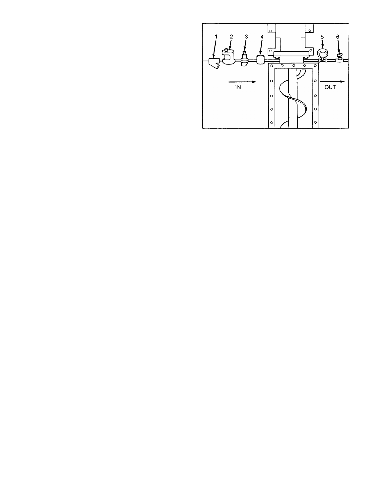
4-3. PACKING ADJUSTMENT
Packing gland nuts should be evenly adjusted so they are little
more than finger tight (See Figure 4-1). Over-tightening of the
packing gland may result in premature packing failure and
possible damage to the shaft and gland.
When packing is new, frequent minor adjustments during the first
few hours of operation are recommended in order to compress
and seat each ring of packing evenly.
1. Upon initial start-up of the pump, adjust the gland nuts for a
leakage rate of 1 – 2 drops per second until the packing has
seated and adjusted to the operating temperature (approximately
10 – 15 minutes).
2. If leakage is excessive after 15 minutes of operation, tighten
the gland nuts until a desired leakage rate is obtained.
CAUTION: Do not tighten until zero leakage is obtained.
Over-tightening of the packing gland may result in
accelerated wear on the packing and damage to the shaft. In
those situations where no packing leakage can be tolerated,
consult your Moyno Authorized Service Representative.
Figure 4-1. Cross Section of Stuffing Box
4-4. PACKING REPLACEMENT
When tightening the gland nuts can no longer regulate leakage,
remove and replace the packing. Replace as follows:
1. Remove packing gland nuts (47), and slide gland (28) and
clamp collar (33) back along drive shaft (38).
2. Remove packing gland studs(6)
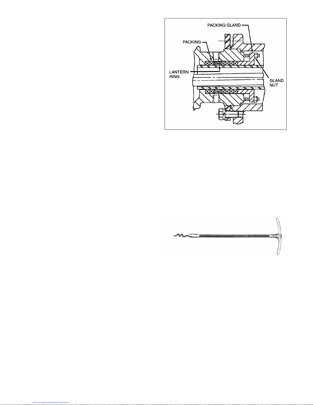
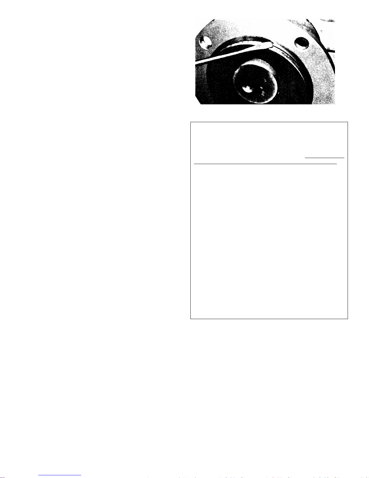
3. Use a pair of packing extractors (Figure 4-2.) to remove four
packing rings (62), lantern ring halves (7), and two additional
packing rings (62).
Figure 4-2. Packing Removal Tool
4. Inspect surface of drive shaft for wear or grooves. If shaft
is worn through the chrome plating into the base metal, or is
badly scored or grooved, it should be replaced.
5. If drive shaft is not worn, install two rings of packing, the
lantern ring halves, and four more rings of packing; lubricating
them before installation with a good grade of packing grease.
Be sure to stagger the packing ring joints at 90-degree
increments (See Section 4-30.).
CAUTION: Always use a proper packing tamper tool to
install packing. Do not use a pointed for sharp tool, as
damage to the packing material or drive shaft could result.
To assure proper shaft lubrication, never use a one-piece
spiral wrap packing.
6. Replace packing gland (28) and secure with packing gland
nuts. (See Figure 4-1.)
7. Adjust packing per Section 4-3.
4
4-5 LUBRICATION
4-6. Bearings. The bearings are lubricated at the factory and
will only need to be re-lubricated when the shaft/bearing
assembly is removed from the pump.
4-7. Gear Joints. Both gear joints are packed with lubricant
during assembly, and will only need to be re-lubricated when
gear joints are disassembled.
4-8. PUMP DISASSEMBLY
NOTE: The following instructions cover ONE procedure for
disassembling all pump components. Major pump components
can be disassembled in various ways since specific installation
location limitations will determine method of component
removal. Reference section 4-51: Table 4-1 G2 Parts List and
section 4-52: G2 Exploded View.
4-9. Disconnect Pump
1. Flush the pump (preferably with clean wa ter) to remove the
pumpage from the unit.
2. Shut off pump.
3. Close suction (if any) and discharge valves.
4. Turn off flush water to packing or mechanical seal, if used.
5. Disconnect power source.
6. Drain any fluid in pump by removing the drain plug (3 4) from
the suction housing (35) or inspection plate (if installed).
4-10. Packing Removal
1. Shut off pump.
2. Complete Section 4-9, Steps 3 – 6.
3. Remove gland adjustment nuts (47), gland studs (6), and
gland halves (28) from stuffing box.
4. Remove packing rings (62). Using flexible packing extractors
(See Figure 4-2.) best does this. Use two extractors
simultaneously on opposite sides of each ring. Pull evenly.
5. Remove lantern rings (7) in similar fashion. Twist split rings
to remove from shaft (38).
6. Remove additional packing rings.
4-11. Stator Removal
1. Complete Section 4-9.
2. Remove section of discharge pipe attached to discharge
flange (8).
3.
4. Remove top half of stator support (13).
5. Unbolt stator clamp ring (9) from suction housing (35). Pull
stator off rotor (see methods below). Remove stator gasket (4).
Use a screwdriver tip to carefully remove stator retaining ring
(39) (See Figure 4-3.). Remove stator clamp ring (9) from
stator (11).
Figure 4.3. Typical Retaining Ring Removal
NOTE: On multiple stage pumps, or when cleaning, checking or
changing stator (11), rotor (14), and/or gear joint assembly, one
of the following procedures is suggested for removing the stator.
Method 1: Utilize Moyno’s Hydraulic Stator Removal Device
(SRD). See separate SRD service manual or contact the local
Moyno distributor for further information on this new product.
Method 2: Use winch-type device anchored directly opposite stat or
end. Attach cable to discharge flange (8) to pull stator (11) off rotor
(14).
Method 3: Remove stator (11), rotor (14), connecting rod (36),
and intermediate shaft (38) as a single unit (See Section 4-12).
Stator can than be taken off the rotor in a more convenient
location. Place the stator (11) in an upright position on the
discharge flange (8). Remove rotor (14), connecting rod (36),
and intermediate shaft (38) from the stator (11). It may be
necessary to use a chain or sling with a lifting device. Anchor
discharge flange (8) securely to the floor before lifting.
If sufficient space is not available to remove the entire drive
assembly (Rotor/Stator, conrod and intermediate shaft), pull the
drive train through the suction housing (35) far enough to expose
the front gear joint. Disassemble the gearjoint at this time, per
section 4-13, and remove the rotor and stator together. If
additional clearance is needed to access the head ring screws
(50), slide adapter flange over the gear joint, or pull stator back
a few inches.
Method 4: Hold stator (11) with pipe or strap wrench and turn
drive shaft (37) slowly in the clockwise direction to unscrew stator
(11) from rotor (14).
6. Remove discharge flange (8) by unbolting from stator clamp
ring (9) and remove stator gasket (4). Remove stator retaining ring
(39) and stator clamp ring from stator (11).
7. Check rotor (14) and stator (11) for wear (See Sections 4-25
and 4-26 for instructions).
4-12. Drive Train Removal
1. Complete Section 4-9 and 4-10.
2. Remove shaft collar screw (49) from the shaft collar (33)
located between the suction housing and bearing housing. Push
drive pin (19) out from the intermediate shaft (38) with punch.
3. Pull the rotor, stator, connecting rod, and intermediate shaft
assembly through the suction housing (35). Adapter flange (27)
and O-Ring (3) will move with the assembly.
4. If sufficient space is not available to remove the entire drive
assembly, pull the drive train through the suction housing far
enough to expose the front gear joint. Disassemble the gearjoint
5
 Loading...