

moyno 1000 Service Manual
SERVICE MANUAL
MOYNO
®
1000 Pumps

TABLE OF CONTENTS
1-1. INTRODUCTION………………………………...
1-2. GENERAL…………………………………1
1-3. SCOPE…………………………………….1
1-4. NAMEPLATE DATA…...…………………1
1-5. Pump Rotation………………… 1
Page
1
4-21a. Mechanical Seals…………….. 7
4-22. Packing…………………………. 7
4-23. Rotor…………………………….. 7
4-24. Stator……………………………. 7
4-25. All Other Parts………………….. 7
1-6. Model Number………………… 1
2-1. INSTALLATION………………………………… 2
2-2. GENERAL…………………………………2
2-3. PIPING……………………………………. 2
2-4. Suction Piping………………… 2
2-5. Discharge Piping……………… 2
2-6. FOUNDATION…………………………… 2
2-7. SHAFT ALIGNMENT……………………. 2
2-8. Coupling Connected Units……3
2-9. Belt Drive Units……………….. 3
3-1. OPERATION…………………………………….. 3
3-2. INITIAL CHECK………………………….. 3
3-3. START-UP……………………………….. 3
3-4. PACKING LEAKAGE……………………. 3
4-1. MAINTENANCE……………………………………3
4-2. GENERAL…………………………………3
4-3. PACKING ADJUSTMENT……………….3
4-4. PACKING REPLACEMENT……………. 4
4-5. BEARING LUBRICATION…………….…4
4-6. DRIVE SHAFT AND ROTOR-
EXTENDED LIFE PROVISION….……... 4
4-7. DISASSEMBLY………………………….. 4
4-8. Disconnect Pump………….…. 4
4-9. Stator Removal……………….. 4
4-10. Suction Chamber Removal….. 5
4-11. Rotor Removal………………... 5
4-12. Connecting Rod or Auger
Assembly Removal ………….. 5
4-13. Packing Removal……………...5
4-14. Drive Shaft Removal………… 5
4-15. Bearing Removal……………... 6
4-16. Gearbox/Gearmotor Removal. 6
4-17. CLEANING……………………………… 6
4-18. INSPECTION…………………………… 6
4-19. Bearings……………………….. 6
4-20. Drive Shaft and Intermediate
Shaft……………………………. 6
4-21. Seals…………………………... 6
4-27. Two-Piece Shaft Models………………. 8
4-27a. Ball Bearing Models…………... 8
4-27b.Tapered Roller Bearing Models. 8
4-28. Close-Coupled Models………………… 8
4-29. Adjusting Bearing End Play ….... 8
4-30. Shaft Installation………………… 8
4-30a. Single Mechanical Seal... 9
4-30b. Double Mechanical Seal. 9
4-31. Connecting Rod or Auger
Assembly………………………… 9
4-32. Suction Chamber……………… 10
4-33. Stator……………………………... 10
4-34. Stator/Support/Discharge
Flange Assembly………………. 10
4-35. Packing…………………………... 10
4-36. Pump Connections……………… 10
4-37. STORAGE……………………………… 10
4-37a. Short-Term Storage……………10
4-37b. Long-Term Storage…………….11
4-38. STANDARD PACKING
SPECIFICATION…………………… 11
4-39. RECOMMENDED SPARE PARTS….. 11
4-40. HOW TO ORDER SPARE PARTS…... 11
4-41. STANDARD HARDWARE LIST STANDARD AND OPEN THROAT
MODELS……………………………….. 12
4-42. STANDARD HARDWARE LIST CLOSE-COUPLED MODELS………. 13
4-43. EXPLODED VIEWS…………………… 13
4-44. Standard Model-Ball Bearing
Design Drive End……………… 13
4-45. Standard Model-Roller Bearing
Design Drive End……………… 14
4-46. Close-Coupled Models…………. 15
4-47. Open Throat Models……………. 16
4-59. TROUBLESHOOTING CHART………. 28
Page
4-26. ASSEMBLY………………………………7
4-26a. One-Piece Shaft Ball Bearing Models…………... 7
4-26b. One-Piece Shaft Tapered Roller Bearing Models.7
4-48. PARTS LIST……………………………. 18
Section:
MOYNO 1000 PUMPS
Page: 1
Date: April 2002
SERVICE MANUAL
MOYNO
1-1. INTRODUCTION
1-2. GENERAL
The Moyno 1000 pump is the most versatile positive
displacement pump available. Its design parameters
have been proven in thousands of applications over the
past 60 years, and it is backed by this same half
century-plus of experience in application and
manufacturing know-how.
The Moyno 1000 pump is a progressing cavity pump.
The pumping action is created by a single helical rotor
rolling eccentrically in the double-threaded helix of the
stator. In its revolution, the rotor forms, in conjunction
with the stator, a series of sealed cavities 180 degrees
apart. As the rotor turns, the cavities progress from the
suction to the discharge. As one cavity diminishes, the
opposing cavity increases at exactly the same rate.
Thus, the sum of the two discharges is a constant
volume. The result is a pulsationless, positive
displacement flow.
1-3. SCOPE
This service manual covers the standard, close-
coupled, and open throat configurations of the Moyno
1000 pump line. Disassembly and assembly procedures
are also covered in this manual.
1-4. NAMEPLATE DATA
The pump nameplate, located on the bearing housing,
or drive adaptor, contains important information relative
to the operation and servicing of the pump. This
information includes the direction of rotation arrow and
the pump model and serial numbers.
The model and serial numbers must be used when
ordering spare parts. To facilitate parts ordering, the
nameplate data for your pump has been recorded
on the nameplate drawing on the front cover of this
manual.
1-5. Pump Rotation. The direction of rotation is
indicated by a rotation arrow on the nameplate.
Standard rotation of Moyno 1000 pumps is clockwise,
when viewed from the driven end of the pump. Close-
coupled models only, are not to be run in reverse.
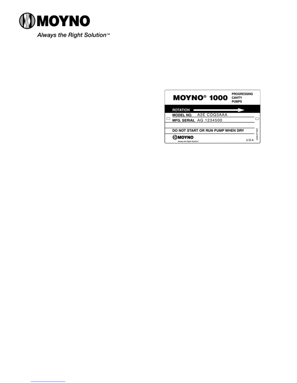
1-6. Model Number. The pump model number is a
series of letters and numbers which identifies the
pump’s basic design and materials of construction. A
typical model number, for example, might be A2E
CDQ3AAA, as shown on the nameplate in Figure 1-1.
1000 PUMPS
Figure 1-1. Typical nameplate showing rotation arrow, model, and
manufacturing serial numbers.
The first three letters and numbers identify the pump’s
basic design characteristics.
In the first space, a letter designates the pump type.
Letters used and their corresponding design types are as
follows:
A = Standard D = High Abrasion, Standard
B = Close-coupled E = High Abrasion, Close-coupled
C = Open throat
The second position number identifies the number of
stages in the pumping elements. This will generally be a 1,
2, or 4.
The third position is a letter, A through K, which identifies
the pump’s capacity in terms of gallons (gal.) per 100
revolutions. Sometimes the third position is followed by the
letter “E” which denotes the pumping element is our Ultra
Pro 23 geometry.The letters, with their corresponding
capacities, are:
A – .38 gal./100 revs. G – 22.0 gal./100 revs.
B – .75 gal./100 revs. H – 36.0 gal./100 revs.
C – 1.5 gal./100 revs. J – 48.0 gal./100 revs.
D – 3.0 gal./100 revs. K – 62.0 gal./100 revs.
E – 6.0 gal./100 revs. L – 115.0 gal./100 revs.
F – 12.0 gal./100 revs.
The next 3 positions, always letters, describe the
pump’s “Materials of Construction” in component
groups of parts.
The first letter in this group identifies the material of the
suction chamber casting.
The second letter indicates the material used in the
rotating parts, i.e., the drive shaft, connecting rod, rotor,

and other metallic parts in contact with the material
being pumped.
The third letter indicates the material of the stator. It
identifies only the stator material and not that of the tube
in which the stator is placed. The tube, a non-wetted
part, is always alloy steel.
A typical designation such as the CDQ used in our
example would result in the following:
C = Cast iron suction chamber
D = Hardened alloy steel internals including drive
shaft, connecting rod, pins, and rotor
Q = Nitrile (NBR) stator (70 durometer hardness)
The following letters identify the materials used in
standard construction:
C = Cast iron
D = Hardened alloy steel
S = Stainless steel, Type 316
Q = Nitrile (NBR), 70 durometer hardness
B = EPDM
F = Fluoroelastomer
The next position is a number identifying the current
pump revision, this manual corresponds to revision 3.
The last three letters indicate the trim code and
denote internal variations in a pump. The first letter
identifies sealing variations. The second letter indicates
internal variations. The third letter indicates rotor
variations.
A typical trim code is AAA, designating the following:
A = Standard black packing
A = Standard plated shaft
A = Standard size chrome-plated rotor
The variations available are:
Sealing:
A – Standard black packing
C – Teflon7 white packing (not food grade)
S – single mechanical seal
D – Double mechanical seal
Internal variations:
A – Standard plated shaft
B – Non-plated shaft
P – Two-piece shaft or pinned close coupled
Rotor variations:
A – Standard plated rotor
B – Non-plated rotor
C – Standard undersize
E – Standard oversize
X – Special to order
*Teflon is a registered trademark of E.I. duPont de Nemours & Co., Inc.
INSTALLATION
2-1.
2-2. GENERAL
Accessibility to the pump and adequate clearance should
be prime considerations in any installation. Enough space
should surround the unit so that maintenance can be
performed with ease.
2-3. PIPING
2-4. Suction piping should be as short as possible.
Normally, the suction line should be the same diameter as
the pump suction; however, conditions such as high
viscosity or required minimum flow velocities may dictate
otherwise. Long-sweep 90 degree elbows or 45 degree
elbows should be used instead of the standard elbow.
Avoid using suction piping loops which trap air.
2-5. Discharge piping diameter should generally be as
large as the discharge port unless fluid conditions indicate
otherwise.
An easily-removable section of piping, at least twice as
long as the stator, should be mated to the discharge port.
This will allow the rotor and stator to be removed without
having to remove the complete pump from the base.
2-6. FOUNDATION
For maximum pump-driver unit life, each unit should be
mounted on a strong steel baseplate. The baseplate should
be mounted on a firm foundation. The motors should be
supported on close-coupled configurations above 1 HP.
2-7. SHAFT ALIGNMENT
After the base has been bolted down to the foundation,
check the following conditions:
2-8. Coupling connected units. Be sure that the pump
and drive shafts are aligned before the coupling is
connected. Care should be exercised to ensure that all
components are level and mounted in a direct line.
Check the gap between coupling halves (refer to coupling
manufacture’s recommendations). Adjustment can usually
be made by loosening the mounting bolts on either the
pump or driver and moving the loosened component into
alignment with the fixed component. Do not use a hammer!
On couplings with equal diameter hubs, it may be helpful to
lay a straight edge across the coupling halves to check
alignment.
2-9. Belt drive units. Be sure that sheaves or sprockets
are in alignment. Check belts for proper tension. Tension
requirements will vary with type of belt, center distances,
and belt speeds. Consult belt manufacturer for specific
recommendations.
2
3-1. OPERATION
3-2. INTIAL CHECK
Before putting the pump into operation, the following
items should be checked to ensure that each piece of
equipment is installed correctly:
-Pump, driver, coupling, or sheave alignment.
-Electrical connections.
-Gauges and other instruments.
-Pump rotation. Rotation is indicated on the pump
nameplate.
-Belt tension on belt driven units. There should be no
appreciable deflection when first starting up.
-All valves should be open on both suction and
discharge sides of pump.
-Seal flush systems if required should be operational.
Double seals require flushing between faces.
CAUTION: This is a positive displacement pump. Do
not operate it against a closed valve.
3-3. START-UP
CAUTION: DRY OPERATION IS HARMFUL TO THE
PUMP! Never allow the pump to operate
without liquid, as dry operation will cause
premature wear of the stator and possible
damage. The stator is lubricated by the
liquid which is being pumped.
1. Before operating the pump for the first time, fill it
with liquid to lubricate the stator for the initial start-up.
Note: If the pump is shut down temporarily, enough
liquid will remain in the system to provide
lubrication upon restarting. It is advisable to
maintain the suction piping at a higher elevation
than the centerline of the pump in order to contain
some liquid in the pump at time of shutdown.
2. Once the pump has been filled with liquid, check for
direction of pump rotation by momentarily starting and
stopping the drive. See pump nameplate for correct
rotation.
3. Start seal flush water if so equipped.
4. Start pump.
3-4. PACKING LEAKAGE
The packed stuffing box is designed to control
leakage, not stop it completely. Leakage is necessary
to reduce friction and dissipate heat.
In a new pump, before the packing has had a
chance to seat properly, excessive leakage through
the stuffing box is common. Frequent adjustments of
the packing gland may be necessary during the first
few hours of operation in order to compress and seat
the packing. See Section 4-3.
4-1. MAINTENANCE
4-2. GENERAL
The Moyno 1000 pump has been designed for a
minimum of maintenance, the extent of which is routine
adjustment of the packing, and infrequent lubrication of
the bearings in tapered roller bearing models. The pump
is one of the easiest to work on because the main
elements are very accessible and require few tools to
disassemble.
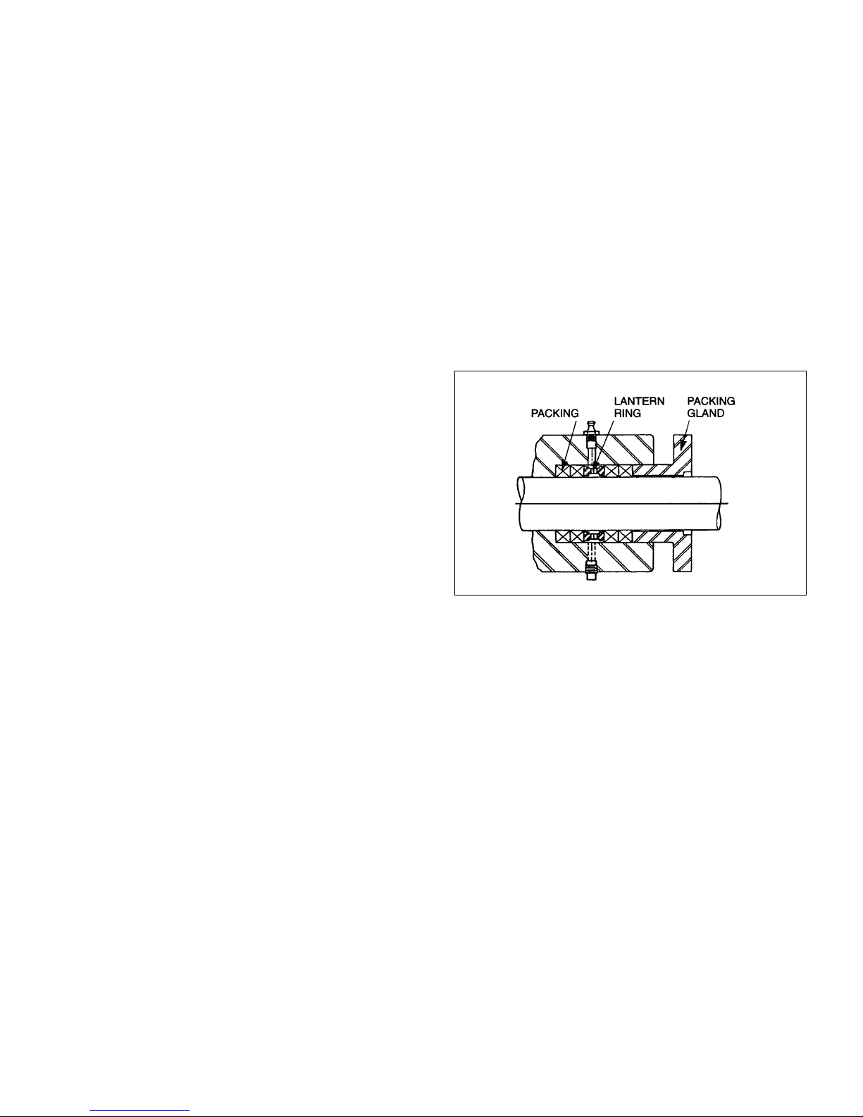
4-3. PACKING ADJUSTMENT
Packing gland nuts (see Figure 4-1) should be evenly
adjusted. Overtightening the packing gland may result in
premature packing failure and possible damage to the
shaft and gland.
Figure 4-1. Cross Section of Packing Retainer
When packing is new, frequent minor adjustments
during the first few hours of operation are recommended
in order to compress and seat the packing.
1. Upon initial start-up of the pump, adjust the gland
nuts for a leakage rate of 50-100 drops per minute until
the packing has seated and adjusted to the operating
temperature (approximately 10-15 minutes).
2. If leakage is excessive after 15 minutes of operation,
tighten the gland nuts ¼ of a turn.
3. Tighten the gland nuts ¼ of a turn after an additional
15 minutes if necessary and repeat this procedure until a
desired leakage of 1-2 drops per minute is obtained.
Adding grease may also reduce leakage by providing a
barrier at the lantern ring.
CAUTION: Do not tighten until zero leakage is obtained.
Overtightening the packing gland may result
in accelerated wear on the packing and
damage to the shaft. In those situations
where no packing leakage can be tolerated ,
consult your Moyno Authorized Service
Distributor.
3
4-4. PACKING REPLACEMENT
Note: In this section, the first reference to each pump
part will be followed by a number or a letter in
parentheses ( ). These numbers and letters are
those used to identify the pump parts and
hardware items in the Exploded Views in Section
4-43.
When leakage can no longer be regulated by
tightening the gland nuts, remove and replace the
packing. The entire pump need not be disassembled to
replace the packing. Briefly, replace as follows:
1. Remove packing gland nuts and lock washers and
slide gland (0900) and slinger ring (6800) back along
drive shaft (6000).
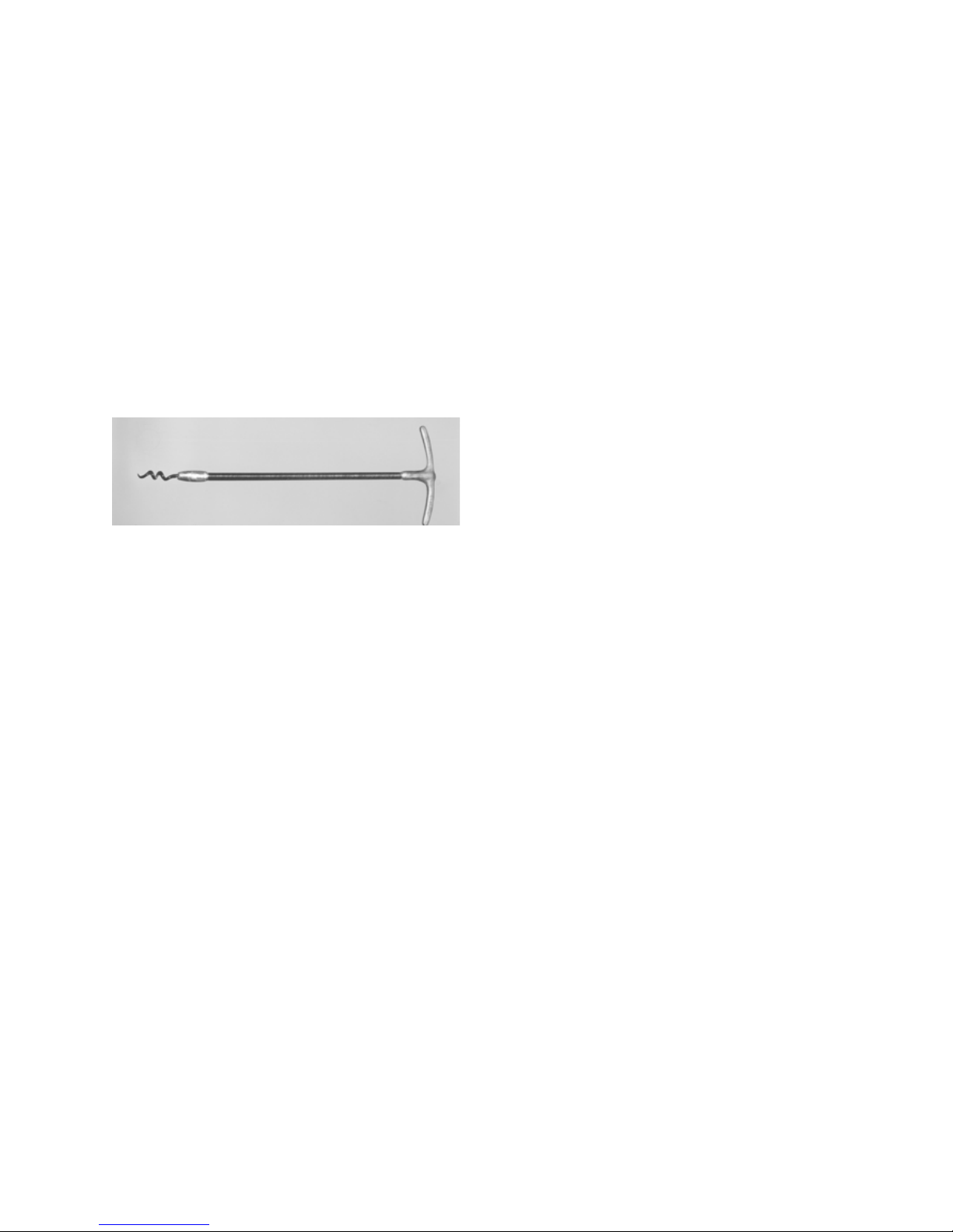
2. Use a packing puller tool (see Figure 4-2) to
remove the packing (6900).
Figure 4-2. Packing Removal Tool
3. Inspect surface of drive shaft for excessive wear or
grooves due to packing rub. If shaft is worn, or is badly
scored or grooved, it should be replaced.
4. If drive shaft is not worn, install a lantern ring and 4
packing rings, lubricating them before installation with a
good grade of packing grease. Be sure to stagger the
packing ring joints at 90 degrees increments.
Note: The stuffing box is supplied with 4 rings installed,
a fifth ring may be added after initial compression.
CAUTION: ALWAYS USE A PROPER PACKING
TAMPER TOOL TO INSTALL PACKING.
Do not use a pointed or sharp tool, as
damage to the packing material or drive
shaft could result. To assure proper shaft
lubrication, never use a one-piece spiral
wrap packing.
5. Replace packing gland and secure with packing
gland screws (H), lock washers, and nuts.
6. Adjust packing per Section 4-3.
4-5. BEARING LUBRICATION
(BEARING MODELS ONLY)
There are two types of bearings used in Moyno 1000
pumps. The smaller models utilize ball bearings which
are lubricated and permanently sealed by the bearing
manufacturer. These bearings cannot be lubricated in
service and generally, due to their low cost and
availability, are changed periodically during routine
maintenance operations.
The larger pumps, including all open throat models, utilize
tapered roller bearings which can be relubricated. Under
normal operating conditions, bearings should not require
replacement or relubrication for at least 15,000 hours or
every 2 years.
To lubricate tapered roller bearings:
1. Remove the drive shaft assembly and the bearings in
accordance with DESASSEMBLY instructions, Sections 414 and 4-15.
2. Clean bearing cups and cones and the shaft assembly
to remove all old grease.
3. Use a good grade of EP (Extreme Pressure) Lithium
soap-base grease such as Mobilux EP2 (Mobil Chemical
Co.), Shell Alvania EP2 (Shell Oil Co.), or equivalent, to
lubricate bearings.
4. Reassemble in accordance with the ASSEMBLY
instructions, Section 4-26.
4-6. DRIVE SHAFT AND ROTOR-EXTENDED LIFE
PROVISION
The heads on the drive shaft and rotor of Moyno 1000
pumps are manufactured with two sets of drive pin holes
located 90 degrees apart.
If, after many hours of service, pin hole wear is
encountered, the drive shaft and/or rotor may be rotated
90 degrees and the second set of pin holes utilized.
4-7. DISASSEMBLY
Note: In this section and in following sections on
CLEANING, INSPECTION, and ASSEMBLY, the
first reference to each pump part will be followed by
a number or letter in parentheses ( ). These
numbers and letters are those used to identify the
pump parts and hardware items in the Exploded
Views in Section 4-43.
4-8. Disconnect Pump
1. Disconnect the power source.
2. Close suction and discharge valves to isolate the pump
from the line.
3. Remove drain plug (N or P) in bottom of suction
chamber (1100) to drain any fluid remaining in pump and
suction line.
4-9. Stator Removal
1. Remove section of discharge pipe attached to
discharge flange (1400).
2. Remove discharge flange (1400) by unbolting from
stator clamp ring (1800) and remove stator gasket (1200).
Remove stator retaining ring (R) and stator clamp ring
(1800) from stator (6500).
4
3. Remove top half of stator support (1700).
4. Unbolt stator clamp ring (1800) from suction
housing, remove stator from rotor, turning stator while
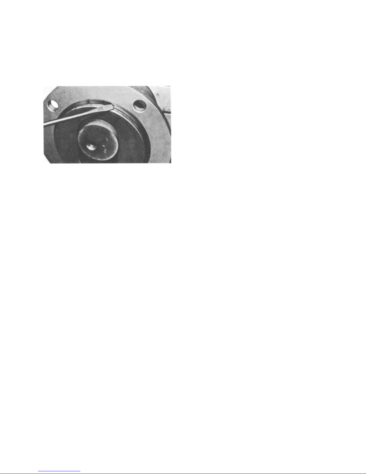
removing will ease disassembly. Use a screwdriver tip
to carefully remove the stator retaining ring. Remove
stator clamp ring (1800) from stator (6500). See Figure
4-3 for the typical retaining ring removal procedure.
Figure 4-3. Typical Retaining Ring Removal
Note: On some four-stage models, a stator adaptor
(1500) and gasket (1210) will be installed
between the stator and suction chamber.
4-10. Suction Chamber Removal
1. On standard and close-coupled models, remove
four suction chamber bolts and lock washers (M)
holding suction chamber to bearing housing (0100). On
open throat models, studs (O) screwed into the bearing
housing are used in place of the suction chamber bolts.
Remove four suction chamber nuts and lock washers
(O) holding suction chamber to bearing housing.
Remove stator gasket from housing.
2. Remove suction chamber and suction chamber
gasket (1220) over the connecting rod (6200) and rotor
on standard models or auger assembly (6200) and rotor
on open throat models.
4-11. Rotor Removal
1. With snap ring pliers, remove the rotor head snap
ring (J), sliding it down over the rotor. Some models
may use spiral type rings (see Figure 4-3).
2. Carefully tap the retaining ring (6100) towards the
rotor end exposing the edge of the universal joint seal
(6400).
3. Remove the edge of the universal joint seal from
the groove in the rotor head and fold the seal back.
4. Carefully tap the retaining ring back towards the
universal joint seal until the drive pin (6300) is exposed.
5. Push the drive pin through the rotor head and
remove the rotor.
6. Remove head O-ring (K) from rotor head.
4-12. Connecting Rod or Auger Assembly Removal
1. Remove the drive shaft head snap ring (J) sliding it
back towards the bearing housing. Some models may have
spiral type rings (see Figure 4-3).
2. Tap the retaining ring towards the bearing housing,
exposing the edge of the universal joint seal.
3. Remove the edge of the universal joint seal from the
groove and fold the seal back.
4. Slide the retaining ring back towards the seal until the
drive pin is exposed.
5. Push the drive pin through the drive shaft head and
remove the connecting rod or auger assembly from the
drive shaft (6000).
6. Remove head O-ring from drive shaft head.
4-13. Packing Removal
To remove packing without removing the drive shaft and
bearing assembly, refer to Section 4-4. If the drive shaft
and bearing assembly are to be removed, proceed directly
to Sections 4-14 and 4-15.
4-14. Drive Shaft Removal
Shaft Drive Models (one-piece shaft, not close-coupled)
The Moyno 1000 pump is designed so that the stuffing
box (1000), packing gland, packing, and bearings (D or E)
are removed as an assembly with the drive shaft. For
Close-Coupled models, skip to Step 17. For two-piece
Shaft Drive models, skip to Step 6.
1. Remove the drive shaft key (I).
2. Remove bearing cover screws and lock washers (A).
Note: Ball bearing models do not have a bearing cover. A
bearing housing snap ring (G), located at the drive
shaft end of the bearing housing, is used to position
the drive shaft and bearings. This snap ring need not
be removed.
3. Slide bearing cover (0300) with grease seal (B) and
bearing shims (6700) off of drive shaft.
4. Using snap ring pliers, remove the bearing housing
snap ring (G) located at the stuffing box end of the bearing
housing.
5. Slide drive shaft assembly from bearing housing.
Shaft Drive Models (two-piece shaft, not close-coupled)
The Moyno 1000 pump is designed with a two-piece drive
shaft available that allows for removal of the drive shaft
head for easy seal maintenance.
6. Remove drive shaft key (I).
7. Move slinger/pin retainer (6800) toward packing or seal
housing, exposing shaft pin.
5

8. Remove shaft pin (2000).
9. Pull intermediate shaft from bearing housing
assembly (2100).
10. Inspect the sealing O-ring (2200) and replace if
worn or damaged.
11. Remove mechanical seal and seal housing from
bearing housing, or remove packing stuffing box from
bearing housing.
12. Remove bearing cover screws and lock washers.
Note: Ball bearing models do not have a bearing cover.
A bearing housing snap ring, located at the drive
shaft end of the bearing housing, is used to
position the drive shaft and bearings. Remove this
snap ring.
13. Slide bearing cover (0300) with grease seal (B)
and bearing shims (6700) off of drive shaft.
14. Slide the drive shaft/bearing assembly out of the
bearing housing toward the bearing cover end.
15. Remove, if desired, the bearing housing snap
ring (G) located at the stuffing box end of the bearing
housing.
16. This allows removal of the grease seal housing.
Inspect and replace grease seal if worn or damaged.
Close-Coupled Models Only
The Moyno 1000 close-coupled pump is designed so
that the stuffing box, packing gland, and packing are
removed as an assembly with the drive shaft.
17. Pull back slinger ring on pinned versions, and
push out the pin.
18. On keyed versions, remove set screws (D) in
locking ring (1600). Rotate locking ring 90
degrees. Slide drive shaft assembly from drive
adaptor, uncoupling from output shaft of drive.
Note: There is a flange on the gearbox side of the
locking ring that catches on the back end of the
drive shaft key. By rotating 90 degrees the set
screw holes should be 90 degrees from the key.
This will align a clearance in this locking ring for
removal.
4-15. Bearing Removal (Not Close-Coupled)
1. Remove shaft snap rings (F).
2. Use an arbor press to press bearings from drive
shaft. The first bearing is pressed off with its
accompanying grease retainer (0500). Slide the second
grease retainer off the shaft and then remove the
second bearing.
Note: When replacing drive shaft or bearings on tapered
roller bearing models, it is recommended that both
grease seals be replaced.
3. Remove the grease seal housing (0700) and grease
seal, bearing housing snap ring, slinger ring, packing gland,
packing, and stuffing box from drive shaft, on one-piece
shaft models.
4-16. Gearbox/Gearmotor Removal
Close-Coupled Models Only - Pinned and keyed
1. To remove the gearbox/gearmotor from the pump,
remove the bolts holding the gearmotor to the drive
adaptor.
2. Pull back slinger ring on pinned versions, and push out
the pin.
On keyed versions, loosen and remove two set screws
3.
in the locking ring. Rotate locking ring 90 degrees in
either direction.
4. Disengage gearmotor shaft from the pump drive shaft.
Note: Rotating locking ring aligns the slots in locking ring
with shaft key to allow disengagement.
4-17. CLEANING
Clean parts in a suitable cleaning solvent.
4-18. INSPECTION
4-19. Bearings. As described in Section 4-5 on Bearing
Lubrication, ball bearings (E) are sealed by the
manufacturer and are not designed to be relubricated and
reused. The following inspection procedure applies to
tapered roller bearings (D).
1. After cleaning, rotate bearings very slowly under
hand pressure to feel for smooth and even action. Never
spin a dry bearing. Check for cracks, galling, pitting, burns,
etc. Replace bearing if there is any doubt concerning
complete serviceability; bearings should be readily
available from any bearing source.
4-20. Drive Shaft and Intermediate Shaft. Inspect drive
shaft (6000) and intermediate shaft (2100) if so equipped
for scoring, burrs, cracks, etc. Replace as necessary. The
drive shaft head is equipped with two sets of pin holes.
When one set becomes worn, rotate shaft 90 degrees and
use second set.
4-21. Seals. It is sound practice to always replace grease
seals (B) whenever the drive shaft and tapered roller
bearings are removed.
4-21a. Mechanical Seals. It is sound practice to replace
mechanical seals when the pump is disassembled. Extreme
care should be taken to protect the seal faces from
damage. These are fragile; avoid touching the faces and
keep them clean.
The rubber bellows (Type 43) or equal seals will adhere
to the shaft after assembly and must be replaces if
6
removed from the shaft. The (Type 680) metal bellows
seals or equal use O-rings to seal against the shaft and
may be reused if their condition does not dictate
replacement.
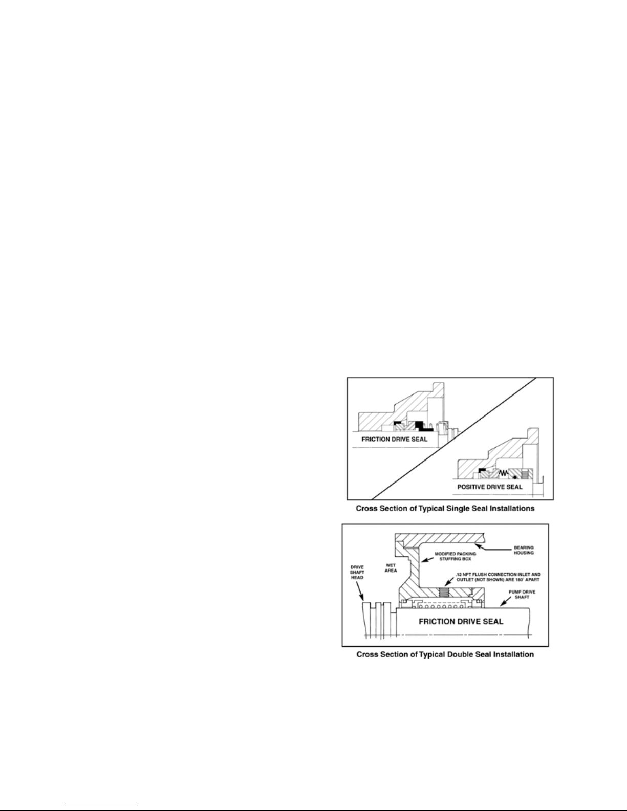
The rubber bellows (Type 43) or equal seals are
friction-driven which makes adhesion to the shaft a
necessity. The metal bellows (Type 680) seals or equal
are positive driven and locked to the shaft with set
screws that must be loosened to remove seal.
4-22. Packing. It is sound practice to always replace
packing (6900) whenever the pump is disassembled.
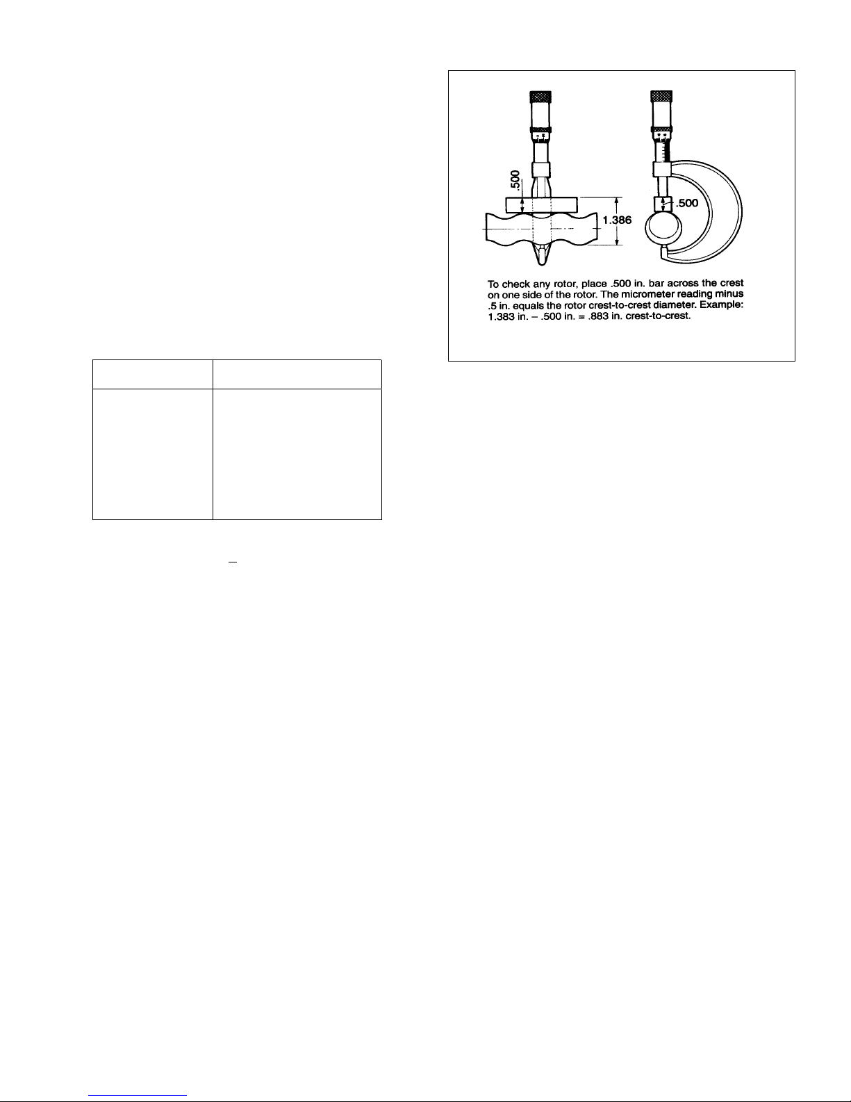
4-23. Rotor
1. To check for excessive rotor (5000) wear, measure
the rotor crest-to-crest diameter (see Figure 4-4) and
compare with the following chart:
Rotor
Size
A
B
C
D
E
F
G
H, J, K
Crest-to-Crest Dia. (inches)
Standard
.886
1.061
1.327
1.671
2.100
2.676
3.428
4.015
The rotor size is designated by the third letter in the
Model Number (i.e., A2ECDQ3AAA).
2. If the measured crest-to-crest diameter is within
.010 in. of the standard value, the rotor is reusable
provided that:
a. the rotor pin holes are not excessively worn.
b. the rotor surface is not cracked, pitted or deeply
grooved (.030 in. or more).
3. Rotors with crest-to-crest diameters greater than
.010 in. under the standard value should generally be
replaced.
Figure 4-4. Measuring Rotor Diameter
4-24. Stator. The best indication of stator wear (6500) and
the need for replacement is a drop in pump performance.
Stators with interior surfaces that are pitted, grooved or
gouged should also be replace.
4-25. All Other Parts. Check for cracks, excessive wear,
damage to threaded holes, burrs, etc. Replace as
necessary. Replace O-rings (K) and all gaskets (1200,
1210, and 1220) at each disassembly and reassembly.
4-26. ASSEMBLY
Bearing Housing (One-Piece Shaft Models)
NOTE: For two-piece shaft models, go to 4-27. For close-
coupled models, go to 4-28.
1. Slide stuffing box (1000) on to drive shaft (6000), large
flanged end first.
2. Slide packing gland (0900) on to shaft so that the
round portion fits into the stuffing box.
3. Place slinger ring (6800) on shaft, adjacent to the
packing gland.
4. Place bearing housing snap ring (G) on the shaft.
4-26a. Ball Bearing Models
1) Press sealed bearing (E) on drive shaft.
2) Install shaft snap ring (F) in groove on shaft. Seat
bearing against snap ring.
3) Install second shaft snap ring.
4) Press second sealed bearing on shaft and seat against
snap ring.
5) If not already in place, install bearing housing snap ring
(G) in groove inside drive end of bearing housing (0100).
7

6) Place assembled drive shaft into bearing housing.
Secure by inserting second bearing housing snap ring in
groove in stuffing box end of bearing housing.
4-26b. Tapered Roller Bearing Models
1) Press grease seal (B) into grease seal housing
(0700) and place assembly on shaft with chamfered
side of grease seal housing facing keyway end of shaft.
2) Pack the bearings (D) thoroughly with grease,
Mobilux EP2 or equal.
3) Place bearing cup on shaft and press bearing cone
on shaft approximately .150 in. beyond snap ring
groove.
4) Place grease retainer (0500) on shaft and install
shaft snap ring (F) in groove on shaft.
5) Seat bearing and grease retainer against snap ring.
6) Install second shaft snap ring in groove on shaft
and place second grease retainer on shaft.
7) Press bearing cone on shaft, and seat bearing and
grease retainer against snap ring.
8) Fill grease seal housing with grease.
9) Slide drive shaft assembly into bearing housing.
Secure by inserting bearing housing snap ring (G) in
groove in bearing housing at rear of stuffing box area.
10) Fill area around the bearing in the drive end of the
bearing housing with grease.
11) Complete bearing assembly by sliding bearing cup
into bearing housing.
12) Press grease seal in bearing cover (0300) and
place bearing cover on shaft. Secure with bearing cover
screws and lock washers (A). (see Section 4-29.)
4-27. ASSEMBLY (Two-Piece Shaft Models)
NOTE: For close-coupled models, go to 4-28.
4-27a. Ball Bearing Models
1) Press sealed bearing on drive shaft.
2) Install shaft snap ring in groove on shaft. Seat
bearing against snap ring.
3) Install second shaft snap ring.
4) Press second sealed bearing on shaft and seat
against snap ring.
5) If not already in place, install bearing housing snap
ring in groove inside stuffing box end of bearing
housing.
6) Place assembled drive shaft into bearing housing.
Secure by inserting second bearing housing snap ring
in groove in drive end of bearing housing. Proceed to 4-
30.
4-27b. Tapered Roller Bearing Models
1) Install bearing housing retaining ring in bearing
housing groove.
2) Press grease seal into grease seal housing and
assemble in housing with chamfered side of grease seal
housing facing bearing location.
3) Slide bearing cup into the bearing housing against the
seal housing.
4) Press bearing cone on shaft approximately .150 in.
beyond snap ring groove.
5) Place grease retainer on shaft and install shaft snap
ring in groove on shaft.
6) Seat bearing and grease retainer against snap ring.
7) Install second shaft snap ring in groove on shaft and
place second grease retainer on shaft.
8) Press bearing cone on shaft, and seal bearing and
grease retainer against snap ring.
9) Fill grease seal housing with grease.
10) Slide drive shaft assembly into bearing housing.
11) Fill area around the bearing in the drive end of the
bearing housing with grease.
12) Complete bearing assembly by sliding bearing cup
into bearing housing.
13) Press grease seal in bearing cover (0300) and
place bearing cover on shaft. Secure with bearing cover
screws and lock washers Proceed to 4-29.
4-28. Close-Coupled Models - Pinned versions are similar to
two piece shaft versions. Locking ring version is listed below.
1) Place locking ring on drive shaft with key clearance
slot aligned with keyslot in drive shaft.
2) Mount drive to the drive adaptor (0100) using four
bolts, lock washers, and nuts.
3) Install drive shaft assembly into the drive adaptor
while coupling drive shaft to output shaft of drive.
4) Rotate locking ring 90 degrees and secure one set
screw over the key and the other set screw at 180
degrees through the hole in the drive shaft, securing
on the output shaft of the drive.
4-29. Adjusting Bearing End Play
(Tapered Roller Bearings Only)
1. Tighten bearing cover screws around bearing cover
firmly, to the point the shaft will not turn. (Screws should be
tightened evenly, opposite each other.)
8
2. Measure the gap between the bearing cover and
the bearing housing.
3. Remove bearing cover and add shims (6700) to
equal gap measured in step 2 plus an additional .010 in.
4. Install bearing cover with shims and tighten screws
evenly, opposite each other.
5. Tap lightly on the shaft head or end using a soft
mallet. Rotate shaft to “free up” assembly. You should
be able to rotate the shaft by hand.
6. Shims may be added or subtracted to get the
proper setting.
7. Slide the rubber pin retainer on the drive shaft
pushing past the pin hole.
4-30. Intermediate Drive Shaft Installation (Mechanical
Seal Pumps Proceed to 4-30a.)
1. Position the packing in the stuffing box and install
the gland studs, if removed.
2. Position the stuffing box in the bearing housing,
sliding the packing gland on packed models onto the
gland studs. Rotate the stuffing box so that the zerk
fitting is on the side.
3. Install the intermediate shaft seal ring (2200) on
the intermediate shaft.
4. Insert the intermediate shaft through the stuffing
box, seating the end of the intermediate drive shaft into
the drive shaft. Rotate the shafts to align the pin holes
and insert the pin.
5. Slide the rubber pin retainer in place on the drive
shaft over the pin.
4-30a. Mechanical Seal Installation (Single Seal)
1. Install the stationary component (seat and O-ring)
of mechanical seal (6950) in seat of seal retainer
(1000).
2. Position the seal housing in the bearing housing
(1).
3. Slide the rotating component (spring and rotating
seat) onto the drive shaft. It may be necessary to wipe a
small amount of lubricant around inside diameter of
rotating component.
4. Lock mechanical seal set screws onto shaft if
mechanical seal is positively driven, locating the end of
the seal flush with the end of the drive shaft.
5. Install the intermediate shaft O-ring (2200) on the
intermediate shaft.
6. Insert the intermediate shaft into the drive shaft.
Rotate the shafts to align the pin holes and insert the
drive shaft pin, compressing the mechanical seal spring on
single spring friction drive seals.
7. Locate slinger/pin retainer on the shaft covering the
pin.
4-30b. Mechanical Seal Installation (Double Seal)
1. Press the stationary seat into the gland for a double
seal installation, taking care not to damage the face. Put
gland on shaft with care.
2. Install the seal on the shaft.
3. On double seal models the seal housing (modified
packing stuffing box) is slid on the shaft, with stationary
seat fitted into place. The seal assembly is then
compressed by bolting the gland to the seal housing. This
will bring the faces into contact.
4. Install the intermediate shaft O-ring (2200) on the
intermediate shaft.
5. Insert the intermediate shaft into the drive shaft.
Rotate the shafts to align the pin holes and insert the drive
shaft pin.
6. Locate the slinger/pin retainer on the shaft covering
the drive shaft pin.
4-31. Connecting rod or Auger Assembly
1. Install universal joint seal (6400) on connecting rod (or
auger assembly) (6200), making sure the raised ridge
inside the universal joint seal is placed in the matching
groove on the connecting rod.
9
 Loading...