

moyes LITESPORT 4, LITESPORT 5 Owner's Manual

Moyes Delta Gliders Pty. Ltd.
Version 1.01
LITESPOR
T
owners manua
l


LITESPORT OWNERS MANUAL
Version 1.01 1
CONTENTS
Amendments.........................................................................................2
Introduction...........................................................................................3
Description of Design............................................................................4
Specifications........................................................................................5
Operating Limitations ............................................................................6
Disclaimer.............................................................................................7
Assembly Procedures...........................................................................8
Pre-Flight Check.................................................................................16
De-Rigging the Litesport.....................................................................18
Flying The Moyes Litesport.................................................................22
Tuning Hints........................................................................................26
Glider Care.........................................................................................30
Maintenance Schedule.......................................................................32
Sail Removal.......................................................................................33
Checking The Litesport Stability System............................................34
AN Bolt Index.................................................................................35
Purchase Record................................................................................36
Maintenance Log................................................................................36

LITESPORT OWNERS MANUAL
2 Version 1.01
AMENDMENTS
Version Date Changes
1.00 20/08/2003 Created original owners manual.
1.01 5/05/2004 • Added Zoom Upright Assembly Drawing
• Updated Stability System instructions

LITESPORT OWNERS MANUAL
Version 1.01 3
Moyes Delta Gliders Pty. Ltd.
1144 Botan
y
Road, Botany NSW 2019 Australia T: +61 (0)2 9316-4644 F: +61 (0)2 9316-8488 E: moyes@moyes.com.au
INTRODUCTION
Thank you for choosing the Moyes Litesport. You have chos en wisely. The
Litesport incorporates the latest hang gliding design innovations to bring
Moyes into the future. The Litesport bridges the gap between intermediate
and topless gliders, providin g a very capable glider for either the advancing
pilot, or the an advanced recreational pilot.
Since 1967, Moyes Delta Gliders has strived to be on the cutting edge of
developing hang gliders of the highest calibre. A family owned business
operating under homespun values, we aim to provide a comprehensive
international network to service all pilots. E ven further, we work with some of
the best pilots in the world to ensure that our gliders ar e stringently ma de and
tested in order to improve their performance, handling, and safety.
We wish you the very best flying,
The Moyes Team

LITESPORT OWNERS MANUAL
4 Version 1.01
DESCRIPTION OF DESIGN
Designed by elite competition pilots, the M oyes Litesport is intend ed for competitio n and
enjoyable high performance cross countr y flying. The Lite sport utilises a planform sim ilar
to the Litespeed.
The Litesport features a 7075T6 aluminium airfra me, which allows a co nsider able weight
saving over more conventional alloys. The leading edge uses a step down taper design
with revised sleeving and tube diameters. This produces a lighter outer leading edge
with an improved flex distribution. The low roll in ertia provides pleasant handling.
The elliptical fibreglass wing tip has been a feature of Moyes high performance gl iders
since the early 80’s. The fibreglass tip creates better turn coordination compared to
conventional designs. With the VG fully engaged, t he fibreglass tip produces a tighter
mainsail and more desirable washout distribut ion.
The pitch stability system utilises a cable braced outer aluminium sprog, providing
support for battens 8 and 9 via a transversal batten. This system was designed with
maximum strength and stiffness in mind, and demonstrates excell ent structural integrity
under any flight load. In addition, the k ingpost incorporates the G-string compensation
system, which lowers the rear of the sail when the VG is engaged. This allows the luff
line to adjust to the decrease in washout produced by the VG system.
The Litesport sail has a total of 8 internal cloth ribs. These ribs prevent the under
surface from ‘blowing down’, which makes pilot i nduced oscillations less likely. These
internal ribs are shaped to produce th e desired under surface camber for low drag at
high speeds.

LITESPORT OWNERS MANUAL
Version 1.01 5
SPECIFICATIONS
Model Size Litesport 4 Litesport 5
Area
13.8sq m
149 sq ft
14.9 sp.m
160 sp ft
Span
9.6 m
31.5 ft
10 m
32.8 ft
Nose Angle 127 - 129 degrees
127 – 129 degrees
Aspect Ratio 6.7
6.7
Glider Weight
31.8 kg
70 lb
32.5 kg
72 lbs
Optimal Pilot
Weight
75 kg
165 lb
90 kg
198 lb
Hook-In-Weight
68-109 kg
150-240 lb
79-129 kg
175-285 lb
Packed-Length
4950 mm
16.2 ft
5150 mm
16.9 ft
Short-Packed
Length
4330mm
14.2 ft
4500 mm
14.8 ft
C of G
(Front of Keel)
1390 mm
54.7 inches
1430 mm
56.3 inches
Number of
Battens:
Mainsail
Undersurface
21
6
21
6
VNE
85kph
53mph
85kph
53mph
VA
74kph
46mph
74kph
46mph
Trim Speed
34kph
21mph
34kph
21mph
Stall Speed
26kph
16mph
24kph
15mph
Max Speed
97kph
60mph
97kph
60mph
Best Glide Speed
40kph
25mph
47kph
29mph
Best Glide Angle 14:1 14:1
Glide Angle 10:1
58kph
36mph
58kph
36mph

LITESPORT OWNERS MANUAL
6 Version 1.01
OPERATING LIMITATIONS
Your Moyes Litesport is a sophisticated high performance hang glider. If maintained
correctly it will give you years of safe enjoyable so arin g. Howev er, it is im porta nt that you
display a healthy respect for all aspects of aviation and that you understand the
increased risks of flying in danger ous c onditio ns or in a m anner that exc eeds t he gli der’ s
operating limitations.
• Flight operation should be limited to no n-aerobatic manoeuvres where the glider’s
attitude does not exceed 30 degrees above or belo w the horizon and bank angles
do not exceed 60 degrees.
• The Moyes Litesport has been designed for foot launched soaring flight and should
not be flown by more than one person at a t i me. It sh oul d not be fl ow n bac kwar ds o r
inverted.
• The recommended minimum pilot skill level is Intermediate.
• The Moyes Litesport can be flown with a uxiliary power when fitted accord ing to the
recommendations of the manufacturer. The user assumes all liabilities.
• The Moyes Litesport should not be flown in excess of the placarded VNE or VA.
• VNE (speed never to exceed): 53mph / 85kph
• VA (maximum rough air manoeuvring speed): 46mph / 74kph
• Stall speed with maximum pilot weight: Less than 25mph / 40kph
• Maximum speed with minimum pilot weight: Less than 50mph / 80kph
The Moyes Litesport will resist spinning and will recover quickly if control forces are
relaxed. Recovery from a stalled turn ca n be achieved with little height loss and without
much attitude change if the control bar is brought back to a normal flying po sition. This
will allow the glider to return to normal flight within half a turn.
The Moyes Litesport has been tested to the following:
• Maximum lift angle of attack at a speed of 65mph/105k ph
• Negative 30 degrees angle of attack at a speed of 46mph/74kph
• Negative 150 degrees angle of attack at a speed of 32mph/54kph
• Pitch moment tests at 20/32, 37/59 and 54/87 (mph/kph)
These tests confirmed the glider’s structural integrity and positive pitch stability
throughout a broad range of angles of attack.
The Moyes Litesport is capable of flying at speeds gr eater than the VA and VNE. We
recommend the use of an accurat e airs p eed i ndic ator to beco me fam ili ar with co ntr ol bar
positions at these speeds and normal flying speeds.

LITESPORT OWNERS MANUAL
Version 1.01 7
DISCLAIMER
The owner and operator must understa nd that due to the inherent risk i nvolved in flying
such a unique vehicle, no warranty is mad e or implied, of any kind, against accidents,
bodily injury, or death. Operations such as aerobatic manoeuvres or erratic pilot
technique may produce equipment failure.
This glider is not covered by product liability insurance, neither has it been designed,
manufactured, or tested, to any state or federal governme nt airworthiness standard or
regulation.
LITESPORT OWNERS MANUAL
8 Version 1.01
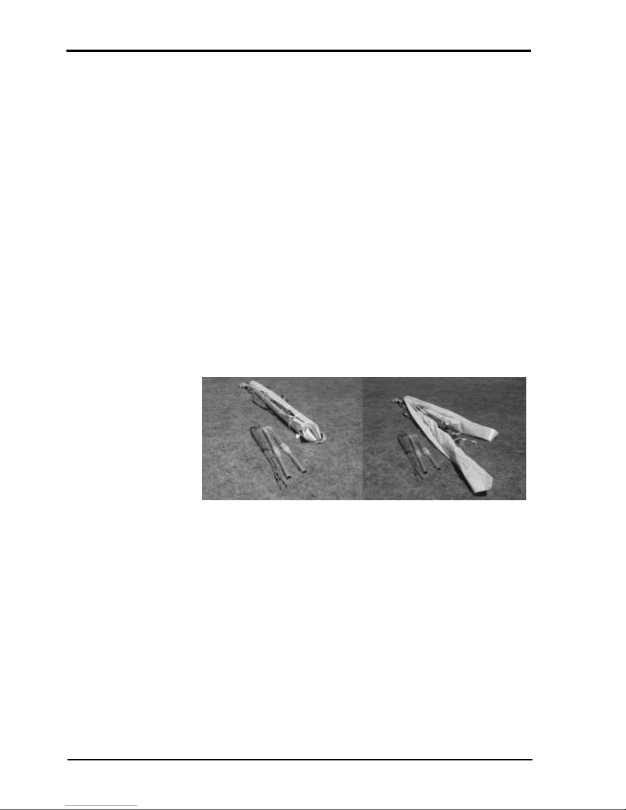
GETTING STARTED
Your new Moyes Litesport may have been shipped to you in the 4.5m breakdown form.
If so, you can assemble your glider to its full length by following these assembly
procedures. All references to ‘top’, ‘bottom’, ‘left’, and ‘right’ refer to the glider and pilot
in flying mode.
Please check your packing list.
• Glider
• 2 x back section leading edges: note that the back s ections are labelled left and
right.
• 1 x batten set: red = left/ green = right/ blue = undersurface
• 1 x speed bar
• 2 x tip bags
• 4 x padding pieces: A-frame top & bottom, keel sleeve, king post top
• 1 x Snack Pack with owners’ manual, batten pattern, a nd promotional wear.
Assembly from 4.5m Breakdown Form
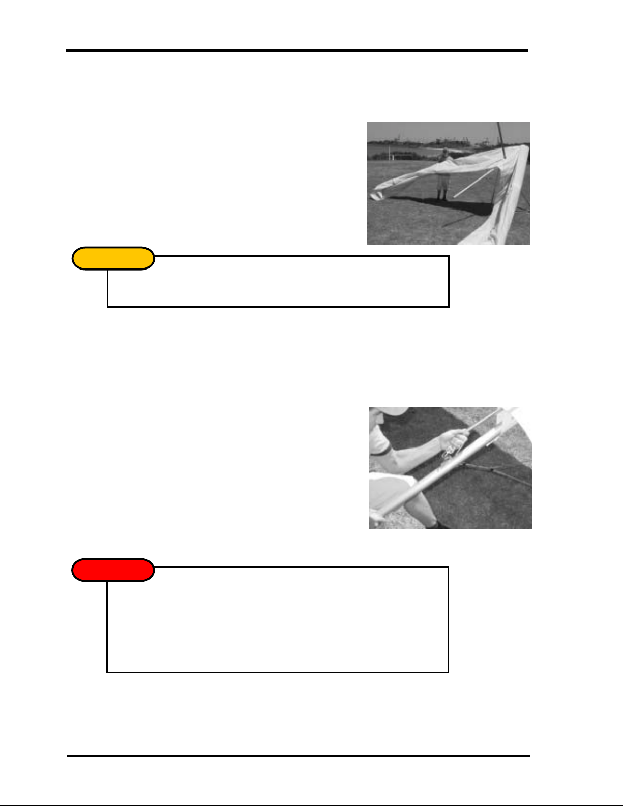
1. Open the glider bag and roll the glider onto its undersurface. Undo the straps and
extend the sail.
Picture 1
Lay the glider on
its undersurface
and unfold the sail.
2. Expose the leading edge/cross bar junction through the inspection zipper. Remove
the bubble wrap and tape from the leading edge/cross bar junction and the end of
the middle sleeve.
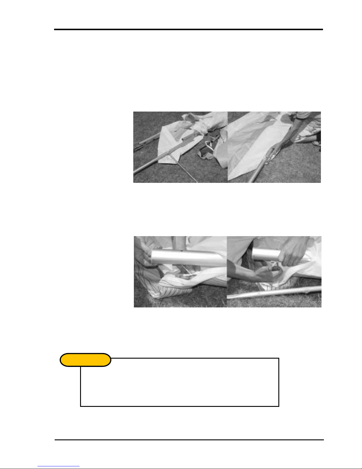
LITESPORT OWNERS MANUAL
Version 1.01 9
3. Insert the right back section of the leading edge. The left and right back sections
differ from each other in the mounting of the outer sprog. You can check this by
picturing that the cable must be on the top of the leading edge and the sprog must
fold outwards. Push the back section into the mid sleeve while depressing the push
button pin. Continue to slide the back section in until it reaches its stop, then rotate
the back section until the mid sleeve location hol es align with the push button pin.
Closely check that the push button pin has fully release d a nd that the back section
cannot be rotated.
Picture 2
Insert the back
ends of the leading
edge.
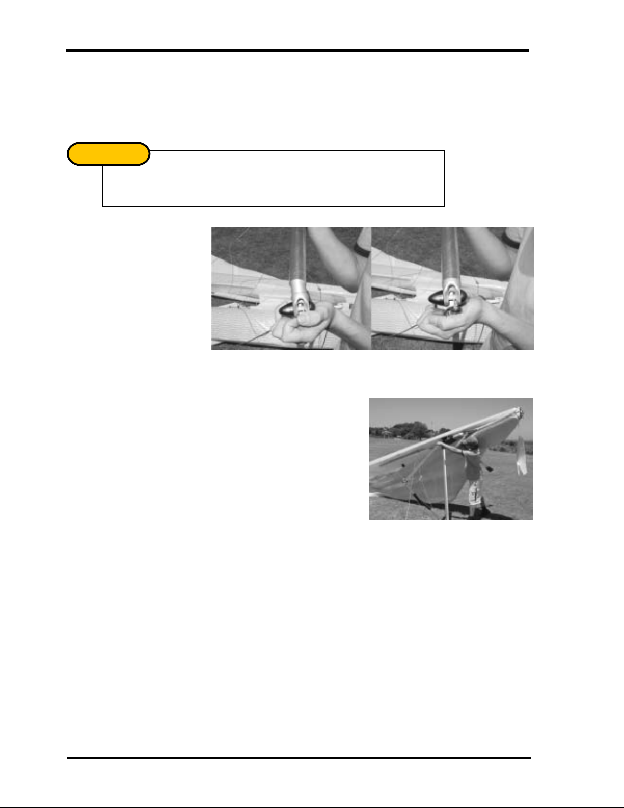
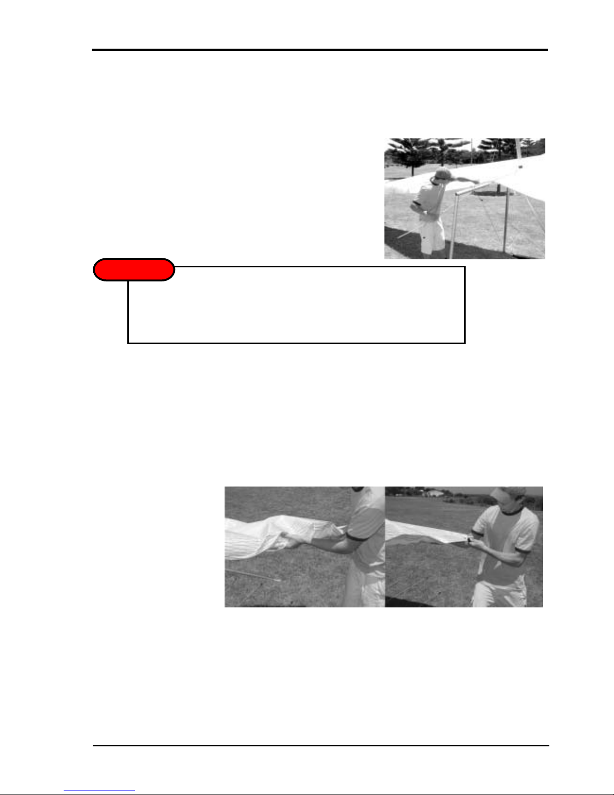
4. Secure the sail by attaching the tip webbin g to the end of the leading edge, using
the clevis pin and safety ring supplied. Insert the pin through the webbing and into
the bottom hole at an angle. Straighten the clev is pin while sliding the webbing
towards the leading edge as shown in P icture 3. Ensure the tip webbing is not
twisted and is on the bottom of the leading edge.
Picture 3
Insert the sail pin
Into the end of the
leading edge.
5. Repeat 1-4 to install the left back section. Your Litesport wil l now be ready for
standard assembly. Before each flight, carefully inspect all tubing, nuts, and bolts, to
ensure no damage has occurred during transportation.
The outer sprog must exit the sail from the long cord wise zipper. The zipper
must be opened when the glider is in standard break down form with the
sprog folding towards the wing tip.
IMPORTANT
!
LITESPORT OWNERS MANUAL
10 Version 1.01
With standard uprights, the uprights will naturally toe-in as shown in Picture 4.
Hold the base bar and the upright, twisting the upright so the conn ection line s up.
ASSEMBLY PROCEDURES
1. Place the glider on the ground, zipper facing up. Op en the bag, undo the ties, and
remove the A-frame bottom padding and battens.
2. Assembly the A-Frame.
Picture 4
Standard uprights
and basebar
assembly.
3. Roll the glider over so that it is standing on the control frame.
Picture 5
Standard uprights
and basebar
assembly.
4. Remove the glider bag and any remaining ties and padding.
NOTE
!
LITESPORT OWNERS MANUAL
Version 1.01 11
After initial assembly it is suggested that the nose batten be left in but pulled
out slightly and left beside the nose plate for pack-up. During setup, check
that the nose batten sits over the lug on the keel securely.
NOTE
!
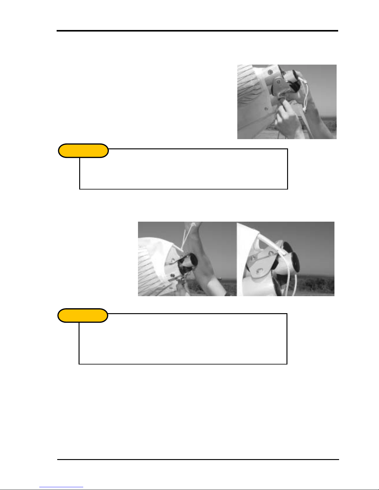
5. Insert the ring of the lower front wires into the Bailey Block, making sure that the
spring is firmly closed and the wires are not twisted.
Picture 6
Attaching the front wires to the Bailey Block.
6. Insert the nose batten. The batten may need some “feedin g” through the Sail by
pulling the sail forward to remove any wrinkles as the batten slides into its pocket.
Picture 7
Insert the nose
batten.
Check that the bottom wires are not twisted or kinked and the hardware is
properly aligned.
NOTE
!
LITESPORT OWNERS MANUAL
12 Version 1.01
7. Carefully spread each wing, making sure that you do not raise them above the level
of the keel. Ensure that the king post rises straight up. This preve nts the twisting of
the keel mount channel bracket.
Picture 8
Spread the wings carefully.
8. To tension the crossbar, pull the cord coming out of the keel pocket. Check that the
cable and rope are not twisted and that the shackle is secured within the Bailey
Block. Attach the king post rear wire behind the shackle, in the Bailey Block. In
strong winds the glider can be difficult to tension. Have a helper gently raise and
pull forward one wing.
Picture 9
Tension the Glider.
Check bottom wires are not twisted or kinked.
NOTE
!
DO NOT USE EXCESSIVE FORCE WHEN TENSIONING THE GLIDER.
If excess force is encountered check:
! The side wires are not twisted or kinked
! The cross bar retainer wire is not caught on the nose plate assembly
! The pull back wire or VG pulleys are not caught in the hang loop assembly
WARNING
LITESPORT OWNERS MANUAL
Version 1.01 13
9. The Litesport is equipped with a rem ovable keel aft section. The glider can be left
resting on it, facilitating the fitment of the washout strut and battens. If desired, the
glider may now be raised onto its keel to complete the assem bly. This also assists
with keeping the sail clean by keeping the tips off the ground.
Picture 10
Raising the glider onto the keel can m ake
assembly easier and keeps the sail clean.
10. Gently insert battens 1- 6, moving from the centre of the wing towards the mid span.
Use light force when inserting the battens, as this will greatly extend the longevity of
the batten pockets. Red tipped battens are for the left wing, green for the right, and
blue for the under surface.
11. Open the zipper at the tip of the sail. Slide the fibreglass rod through the end of the
sail and into the end of the leading edge. Ensure that the rod is pushed hard against
its stop.
Picture 11
Insert the glass
wing tip
The glider may fall to one side if pushed or blow n b y the w in d - this m ay result in
wing tip damage. It is recommended that you only use in fl at level groun d and i n
nil wind. Use with care!
WARNING
!
 Loading...