

moyes LITESPEED Owner's Manual

l
LITESPEED
owners manua
Moyes Delta Gliders Pty. Ltd.
Version 1.01


LITESPEED OWNERS MANUAL
CONTENTS
Amendments ..........................................................................................2
Introduction.................... .........................................................................3
Description of Design.................... .. ... .... ... .. ... .. ..... .. .. ... .. ..... .. .. ... .. ..... .. .. .4
Specifications .........................................................................................5
Operating Limitations .............................................................................6
Disclaimer....................................................... ........................................7
Getting Started ..................................... ... .. ..... .. .. ... .... ... .. ..... .. .. ... ..... .. .. ...8
Assembly Procedures ..........................................................................11
Pre-Flight Check............ .......................................................................16
De-Rigging the Litespeed............ .. ... .. ..... .. .. ... .. .. ... .... ... .. .. ... .. ..... .. ... .. .. .18
Flying the Moyes Litespeed .................................................... .............22
Tuning Hints..........................................................................................26
Performance Tuning.............................................................................28
Glider Care............................................. ..............................................30
Maintenance Schedule.........................................................................32
Sail Removal ........................................................................................33
List of Fasteners & Airframe Bolts .......................................................34
AN Bolt Index...................................................................................34
Checking The Litespeed Stability System ...........................................35
Purchase Record............. .. ... .... ... .. .. ..... ... .. .. ... .... ... .. .. ... .... ... .. .. ..... .. ... .. .37
Maintenance Log..................................................................................37
Version 1.01
1

LITESPEED OWNERS MANUAL
AMENDMENTS
Version Date Changes
1.00 24/12/2002 Converted Owners Manual to new format.
1.01 28/7/2003 1. Updated all assembly drawings.
2. Corrected page 9 paragraph 4 – referring to the positioning of the
sail webbing.
Version 1.01
2

LITESPEED OWNERS MANUAL
y
INTRODUCTION
Thank you for choosing the Moyes Litespeed. You have chosen wisely.
The Litespeed incorporates the latest high performance hang gliding
design technology.
Since 1967, Moyes Delta Gliders has strived to be on the cutting edge of
developing hang gliders of the highest calibre. A family owned business
operating under homespun values, we aim to provide a comprehensive
international network to servic e all pilots. Even further, we work with some of
the best pilots in the world t o ensur e that our glider s ar e string ently made an d
tested in order to improve their performance, handling, and safety.
We wish you the very best flying,
The Moyes Team
1144 Botan
Version 1.01
Road, Botany NSW 2019 Australia T: +61 (0)2 9316-6466 F: +61 (0)2 9316-8488 E: moyes@moyes.com.au
Moyes Delta Gliders Pty. Ltd.
3

LITESPEED OWNERS MANUAL
DESCRIPTION OF DESIGN
The Moyes Litespeed is a glider designed by elite competition pilots for competition and
enjoyable high perfor mance cross country flying. The Litesp eed utilises a similar plan
form as its predecessors the Xtralite and CSX, and has improved other facets of the
glider to provide better performance, safety and handling.
The Litespeed features a 7075 aluminium airframe which allows minimum weight with
excellent flex characteristics. The leading edge features a step down taper design with
revised sleeving and tube diameters to produce a lighter weight outer leading edge with
improved flex distrib ution across the leng th. The weight re duction prov ides consi derable
reduction of inertia and thus roll pressures are minimal.
The elliptical fibre glass wing tip has been a feature of Moyes high per formance gliders
since the early 80’s. The fibre glass tip creates a washout distribution allowin g better
turning coordination than conventional designs. With the full tight VG setting, the fibre
glass tip allows for a tighter mainsail and a more desirable washout distribution.
The Litespeed features a revised sail design which allows for minimum twist without
losing pitch stability. The double surface has been increased to 92% which provides
better washout control under positive load and allows the enclosed stability system to be
mounted further rearward for better support. The leading edge tension has been markedly
increased to minimise airfoil distortion at high speeds. Many design steps have been
taken to produce a low minimum flying speed and allow easy control at these speeds.
The pitch stability system utilises cable braced inner and outer aluminium sprogs
providing support for battens 7 to 11 via two transversal battens. The inner sprog
features a unique compensator system operating from the geometrical change of the
X-bar to leading edge angle. This allows for the inner sprog to rise 80mm when the VG
is released. The stability system was designed with maximum strength and stiffness in
mind, and demonstrates excel lent structural integrity under any flight load.
The Litespeed sail has a total of 8 internal cloth ribs. These internal ribs restrict the
under surface from ‘blowing ou t’ which prevents pilot induced osci llations. The internal
ribs are cut to a specific airfoi l, whic h pro duc es the de si red un der sur fac e c am ber for lo w
drag high speed gliding.
The Litespeed features a spar constructed entirely of pre-impregnated carbon fibre cloth.
The pre-impregnated carbon provides maximum consistency in production. The spar
utilises combinations of biax ial fibre and unidirectional fibre to produc e load absorbing
flexibility and maximum impact resistance.
Version 1.01
4

LITESPEED OWNERS MANUAL
SPECIFICATIONS
Model Size Litespeed 3 Litespeed 4 Litespeed 5
Area
Span
12.6sq m
136 sq ft
9.6 m
31.5 ft
13.6sq m
146 sq ft
10.0 m
32.8 ft
14.5sq m
156 sq ft
10.4 m
34.1 ft
Nose Angle 130 to 132 deg 130 to 132 deg 130 to 132 deg
Aspect Ratio 7.2 7.4 7.5
Glider We ight
Hook-In-Weight
Packed-Length
Short-Packed Length
C of G Front of Keel
31.9 kg
70.4 lb
55-95kg
120-210 lb
4845mm
15’11”
4200mm
13’9”
1310mm
51.57”
33.6 kg
74 lb
68-110kg
150-240 lb
4950mm
16’3”
4330mm
14’2”
1363mm
53.66”
34.5 kg
76 lb
75-120kg
165-265 lb
5150mm
16’11”
4500mm
14’9”
1370mm
51.94”
Number of Battens:
Mainsail
Undersurface
VNE
VA
Trim Speed
Stall Speed
Max Speed
Best Glide Speed
21
6
53mph
85kph
46mph
74kph
21mph
34kph
16mph
26kph
77mph
124kph
28mph
45kph
23
6
53mph
85kph
46mph
74kph
21mph
34kph
16mph
26kph
77mph
124kph
28mph
45kph
23
6
53mph
85kph
46mph
74kph
21mph
34kph
16mph
26kph
77mph
124kph
28mph
45kph
Best Glide Angle 15:1 15:1 15:1
Glide Angle 10:1
43mph
69kph
46mph
75kph
45mph
73kph
Version 1.01
5

LITESPEED OWNERS MANUAL
OPERATING LIMITATIONS
Your Moyes Litespeed i s a sophisticated state of the art high performance hang g lider.
If maintained correctly it will give you years of safe enjoyable soaring. However, it is
important that you display a healthy respect for all aspects of aviation and that you
especially understand the increased risks of flying in dangerous conditions or in a
manner that exceeds the glider’s operating limitatio ns.
• Flight operation should be limited to non-aerobatic manoeuvres where the pitch
angle doesn’t exceed 30 degrees up and down to the horizon and bank angles don’t
exceed 60 degrees
• The Moyes Litespeed has been designed for foot launched soaring flight and should
not be flown by more than one person at a time
• It should not be flown backwards or inverted
• The recommended minimum pilot skill level is Advanced (Hang 4)
• The Moyes Litespeed should not be flown with auxiliary power
• The Moyes Litespeed should not be flown in excess of the placarded VNE or VA
• VNE (speed never to exceed): 53 mph / 84.8 kph
• VA (maximum rough air manoeuvring speed): 46 mph / 73.6 kph
• Stall speed with maximum pilot weight: Less than 25 mph / 40 kph
• Maximum speed with minimum pilot weight: Less than 55 mph / 80 kph
The Moyes Litespeed will resist spinning and will recover quickly if control pressures are
relaxed. Recovery from a s talled turn can be achieved without extr eme height loss or
without extreme attitude change if the angle of attack is reduced. Recovery from such an
incipient spin will be achieved within half a turn if the angle of attack is lowered to a
normal flying angle.
The Moyes Litespeed has been tested and certified to the USHGMA and DHV
standards. These standards require ultimate load tests at:
• Maximum lift angle of attack at a speed of 65 mph / 104 kph
• Negative 30 degrees angle of attack at a speed of 46 mph / 73.6 kph
• Negative 150 degrees angle of attack at a speed of 32 mph / 51.2 kph
• Pitching moment tests at 20/32, 37/59 and 54/86 mph/kph respectively, to display
the gliders inherent positive pitch stability through a broad range of angles of attack
The Moyes Litespeed is capabl e of easi ly fly ing at sp eeds greater than the VA and VNE.
We recommend you use an accurate airspeed indicator and familiarise yourself with
control bar positions at these speeds and normal flying speeds.
Version 1.01
6

LITESPEED OWNERS MANUAL
DISCLAIMER
The owner and operator must un derstand that due to the inherent risk inv olved in flying
such a unique vehicle, no warranty is made or implied of any kind against accidents,
bodily injury or death. Operations such as aerobatic manoeuvres or erratic pilot
technique may ultimately produce equipment failure, and are specifically excluded from
the warranty.
This glider is not covered by product liability insurance, nor has it been designed,
manufactured or tested to any state or federal government airworthiness standards
or regulations.
Version 1.01
7

LITESPEED OWNERS MANUAL
GETTING STARTED
Your new Moyes Litespeed may h ave been shipped to you i n the 4.5 metre breakdo wn
form. If so, you can assemble your glider to its full length by following the assembly
procedures. All referen ces to ‘t op’ & ‘bo ttom’ an d ‘left’ a nd ‘right ’ are re ferred to with the
glider in flying mode.
Please check your packin g l ist .
• Glider
• 2 x Back section leading edges: note that the back sections are different between
left and right
• 1 x Batten Set: Right=Green/Left=Red/Blue=Undersurface
• 1 x Speed Bar
• 2 x Tip Bags
• 3 x Padding Pieces: A-Frame top & bottom, Keel sleeve
• 1 x Batten Pattern
• 1 x Snack Pack with owner’s manual and Batten Profile
Assembly from 4.5m Breakdown Form
1. Open the glider bag and roll the glider onto its undersurface.
Undo the straps and extend the sail.
Picture 1
Lay the glider on
its undersurface
and unfold the sail.
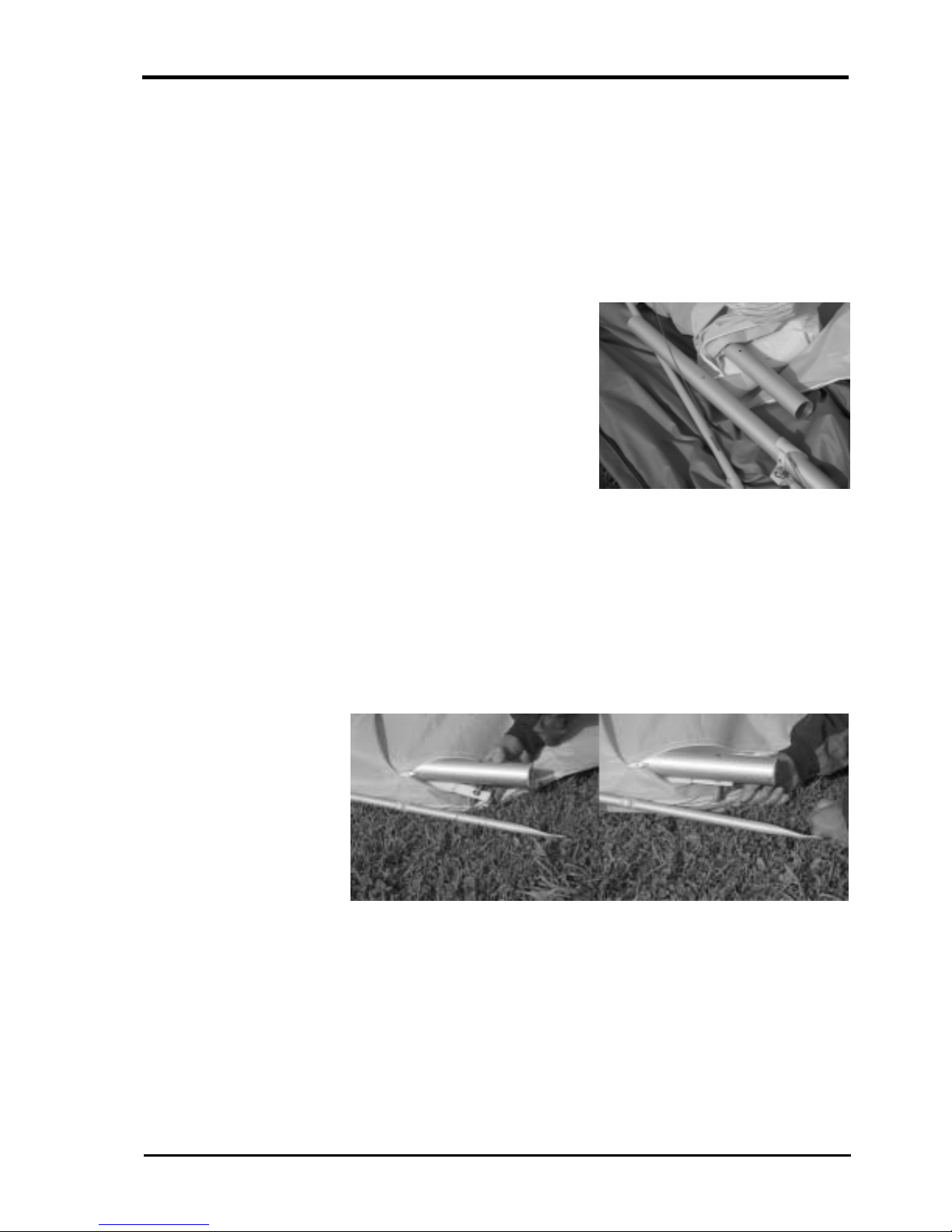
2. Expose the leading edge/cross bar junction through the inspection zip. Remove the
bubble wrap and tape from the leading edge/cross bar junction and the end of the
middle sleeve.
Picture 2
Remove packing materials from leading edge end.
Version 1.01
8
LITESPEED OWNERS MANUAL
3. Insert the right hand back section of leading edge. The right hand back section
differs from the left in the mounting of the outer sprog. You can check this by
picturing that the cable must be on the top side of the lea ding edge and the sprog
must fold inboard. Push the back section into the mid sleeve while depressing the
push button pin. Conti nue to push the back sec tion in until it reaches its stop, then
rotate the back section until the mid sleeve location holes align with the push
button pin. Closely check that the push button pin has fully released and that the
back section is secure against rotation forces.
Picture 3
Insert the back
ends of the
leading edge.
4. Secure the sail by attaching to the ti p web bin g usi ng the cl e vis pi n and rin g sup pli ed.
Insert the pin through the we bbing and into th e bottom hole at an angl e. Straighten
the clevis pin while sliding the webbing towards the leading edge as shown in
Picture 4. Ensure the tip webbing is no t twisted and is on the bottom of the leading
edge.
Picture 4
Insert sail pin into end of leading edge.
Version 1.01
9

LITESPEED OWNERS MANUAL
!
5. Repeat steps 1-4 to install the left hand back section of leading edge.
Your Litespeed will now be ready for the standard assembly. Before flight, make
a thorough inspection of all tubing and nuts and bolts to ensure no damage has
occurred during transportation. (refer to section on pre-flight check).
IMPORTANT
Picture 5
Assembled glider
showing dive sticks
extruding from under
surface zippers.
The inner and outer sprogs must exit th e sail from the l arge cord wis e zippers .
The zippers must be opened when the glider is in standard break down form
with both sprogs folding toward the wing tip outside the sail.
Version 1.01
10
LITESPEED OWNERS MANUAL
!
!
ASSEMBLY PROCEDURES
1. Place the glider on the ground, zipper up. Open the bag, undo ties, remove A-frame
bottom padding and battens.
NOTE
Take special care with the wir es, th e Lites peed featur es 1x 19 cabl e whic h can
easily be kinked unless special care is taken.
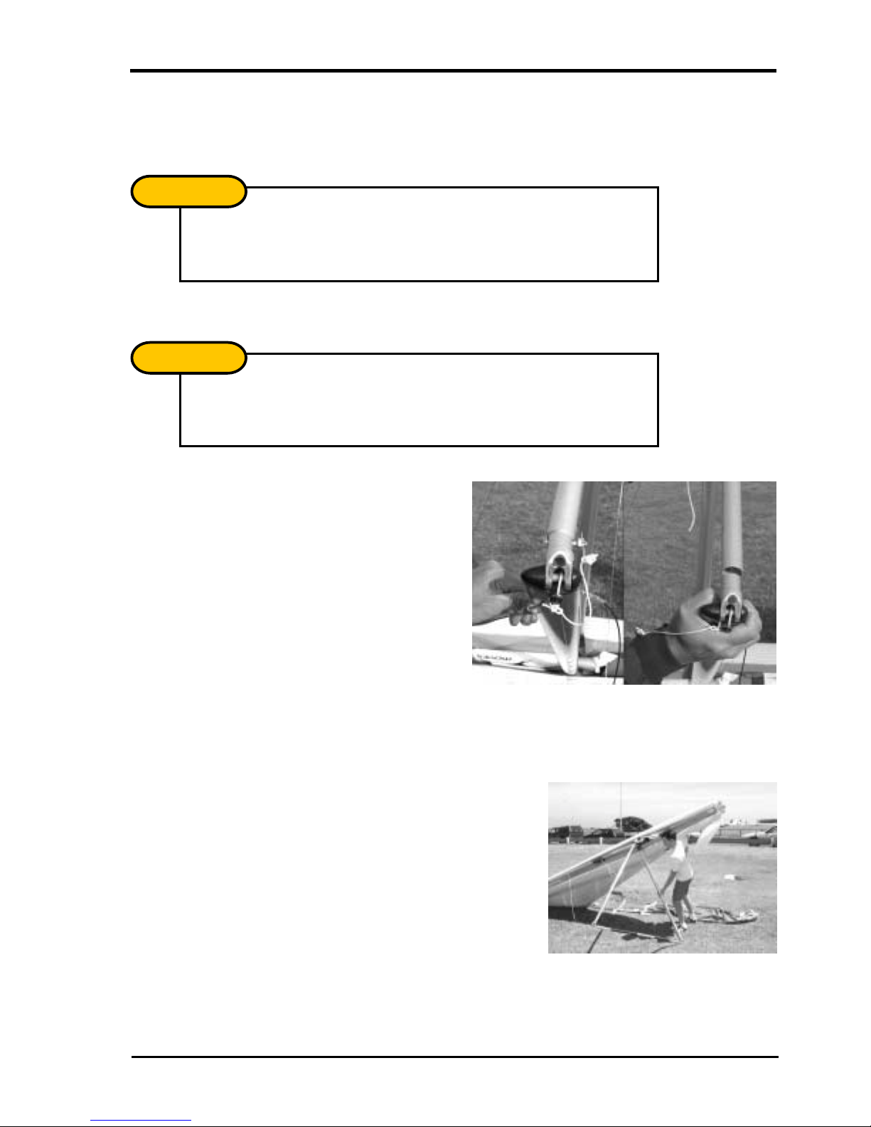
2. Assembly the A-Frame.
NOTE
With standard uprights, the uprights will naturally toe-in as shown in
Picture 6. Hold the base bar and the upright, twisting the upright so the
connection lines up.
Picture 6
Standard uprights and
base bar assembly.
Roll the glider over so that
it is standing on the
control frame.
3. Roll the glider over so that it is standing on the control frame.
Picture 7
Roll the glider onto the
A-frame and attach the
front wire to the Bailey Block.
Version 1.01
11
LITESPEED OWNERS MANUAL
!
!
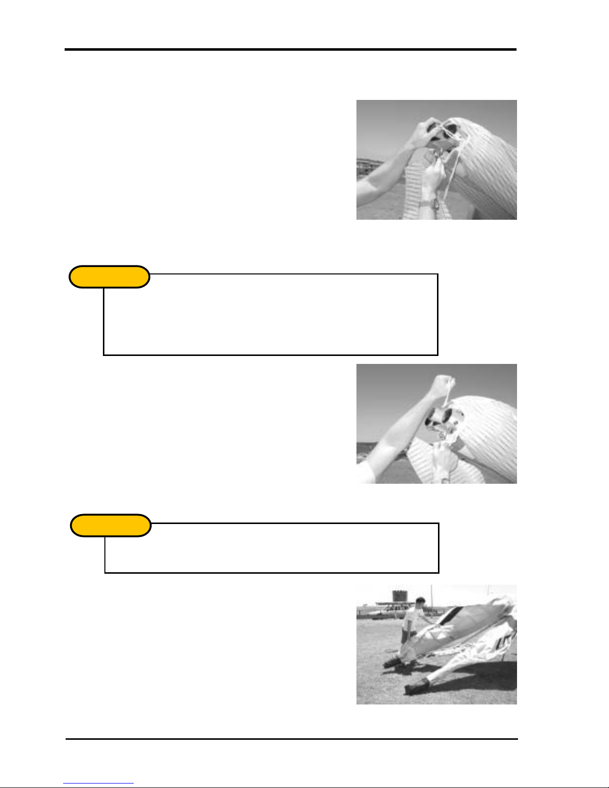
4. Insert the ring of the lower front wires in the Bailey Block making sure that the spring
is firmly locked and the wires untwisted.
Picture 8
Attaching the front wires to the Baileys Block.
5. Insert the nose batten. The batten may need some “feeding” through the Sail by
pulling the sail forward to remove any wrinkles as the batten slides into its pocket.
NOTE
After initial assembly it is suggested that the nose batten be left in but pulled
out slightly and left besid e the nose plate for pack-up. Check that the nos e
batten sits over the lug on the keel securely.
Picture 9
Insert nose batten.
6. Carefully spread each wing making sure that you do not raise them above the keel.
NOTE
Check bottom wires are not twisted or kinked.
Picture 10
Spread the wings.
Version 1.01
12
LITESPEED OWNERS MANUAL
!
!
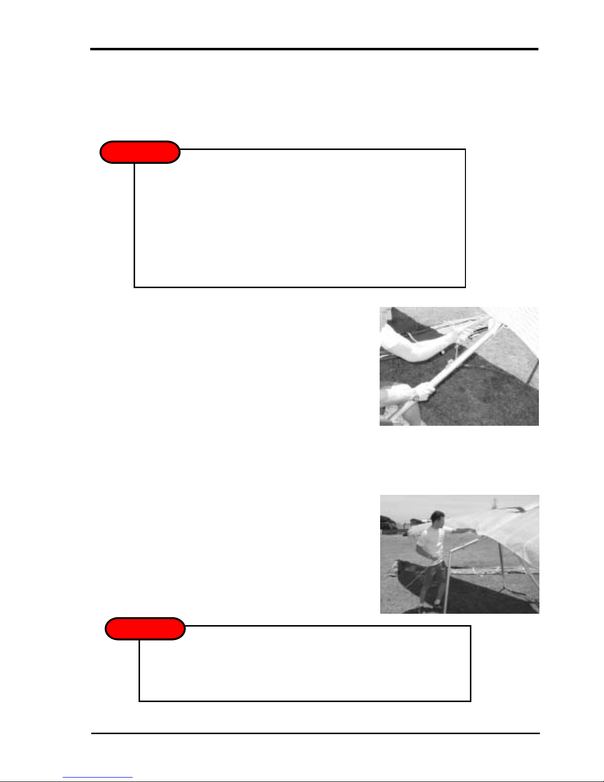
7. To tension the crossbar, pull the cord coming out of the keel aft of the sail.
Check that the cable and rope are not twisted and that the spring lock is firmly
locked. In strong winds the glider can be particularly difficult to tension. Have a
helper gently raise and pull one wing, this reduces the pressure on the centre
section and allows it to slide more freely.
WARNING
DO NOT USE EXCESSIVE FORCE WHEN TENSIONING THE GLIDER.
If excess force is encountered check:
! The side wires are not twisted or kinked
! The cross bar retainer wire is not caught on the nose plate assembly
! The floating cross bar centring w ire is not caught on a cross bar
8. The Litespeed is equipped with a removable keel aft section. The glider can be left
WARNING
assembly junction
! The pull back wire or VG pulleys are not caught in the hang loop assembly
Picture 11
Tension the glider.
resting on it, facilitating the f itment of the was hout struts, and b attens. If desired , the
glider may now be raised onto its keel to complete the assembly. This also assists
with keeping the sail clean by keeping the tips off the ground.
Picture 12
Raising the glider onto the keel can make assembly
easier and keeps the sail clean.
The glider may fall to one side if pu shed or bl own by th e wind - this m ay resu lt in
wing tip damage. It is rec om mended th at yo u onl y use i n flat lev el gro un d and in
nil wind. Use with care!
Version 1.01
13
 Loading...