

Page 1

2014 Moxa Inc. All rights reserved.
Reproduction without permission is prohibited.
P/N: 1802020040011
WAC-2004 Series
Quick Installation Guide
Second Edition, May 2014
Page 2
- 2 -
Overview
The goal of zero-latency roaming is to allow clients to seamlessly
maintain their communications as they move from one access point to
another. The advanced Moxa Wireless Access Controller, the WAC-2004,
together with Controller-based Turbo Roaming technology, enables
millisecond-level roaming over different IP subnets. The advanced
roaming algorithm along with Mobile IP technology allows wireless clients
to roam between APs in different IP subnets within milliseconds while
upholding stringent security in extremely demanding environments. The
WAC-2004 is rated to operate at temperatures of 0 to 50°C and is rugged
enough for on-site installation in any harsh industrial environment.
Package Checklist
The WAC-2004 series wireless access controller is shipped with the
following items. If any of these items are missing or damaged, please
contact your customer service representative.
• WAC-2004 series wireless controller
• 1 AC power cord (C13-type, US or EU)
• 1 serial console cable (DB9-type, female-to-female)
• 4 RJ45 connector protective caps
• Rackmount kit
• Quick installation guide
• Software CD
• Warranty card
Installation and Configuration
Before installing the WAC-2004, verify that all items in the Package
Checklist are in the box.
Note that the WAC-2004 must be configured before use. Refer to the
WAC-2004 Series User’s Manual for more details.
The WAC-2004 has a default IP address of 192.168.127.253, which you
must use when connecting to the device via LAN 1 (LAN 2-4 are reserved
for future expansion) for the first time. When configuring the WAC-2004
for the first time, use the following default user name and password:
User name: admin
Password: root
ATTENTION
For security reasons, we strongly recommend changing the
default password. To do so, select
Maintenance Password
,
and then follow the on
-screen instructions.
To make the changes effective, you must click
Save
Conf
iguration to save the changes (Restart to apply the
changes).
Page 3

- 3 -
Panel Layout of the WAC-2004 Series
Front Panel View
Back Panel View
1. Rackmount kit
2. LAN 1: 10/100/1000 BaseT(X) (RJ45-type)
3. LAN 2-4: reserved for future expansion (RJ45-type)
4. Power reset button
5. LAN1 LEDs: 100M/1000M
6. LAN 2-4 LEDs: reserved for future expansion
7. System LEDs: PWR1, PWR2, FAULT, STATE
8. RS-232 console port (DB9-type, male)
9. Grounding screw
10. Power sockets for AC power inputs:
PWR1, PWR2 (C13-type, US or EU)
Page 4

- 4 -
Mounting Dimensions (unit = mm)
Rackmount
Use six screws to attach the WAC-2004 to a standard rack.
Page 5

- 5 -
Grounding the WAC-2004
Grounding and wire routing help limit the effects of noise due to
electromagnetic interference (EMI). Run the ground wire from the ground
screw on the rear side (shown below) to the grounding surface prior to
connecting devices.
ATTENTION
This product is to be mounted to a well
-grounded mounting
surface, such as a metal panel.
Connecting the Power Inputs
The WAC-2004 supports dual redundant power supplies: Power Supply 1
(PWR1) and Power Supply 2 (PWR2). The connections for PWR1 and
PWR2 are located on the rear side (shown below). Be sure to use a
standard power cord with an IEC C13 connector, which is compatible with
the AC power inlet.
Pin Assignments
Gigabit Ethernet Port Connection
The WAC-2004 offers 1 gigabit Ethernet connector (LAN 1) and 3
reserved Ethernet connectors (LAN 2-4) for future expansion. When the
cable is properly connected, the LEDs on the RJ45 connectors will glow to
indicate a proper connection.
Pin
10/100 Mbps
1000 Mbps
1
ETx+
TRD(0)+
2
ETx-
TRD(0)-
3
ERx+
TRD(1)+
4
---
TRD(2)+
5
---
TRD(2)-
6
ERx-
TRD(1)-
7
---
TRD(3)+
8
---
TRD(3)-
LED
Color
Description
Gigabit RJ45
Connector
Green
100 Mbps Ethernet mode
Amber
1000 Mbps (Gigabit) Ethernet mode
Off
Not operating or 10 Mbps Ethernet mode
Page 6
- 6 -
NOTE
The pin numbers for the 8-pin RJ45 connectors (and ports) are
typically not labeled on the connector (or port). Refer to the
diagram above to see how the RJ45’s pins are numbered.
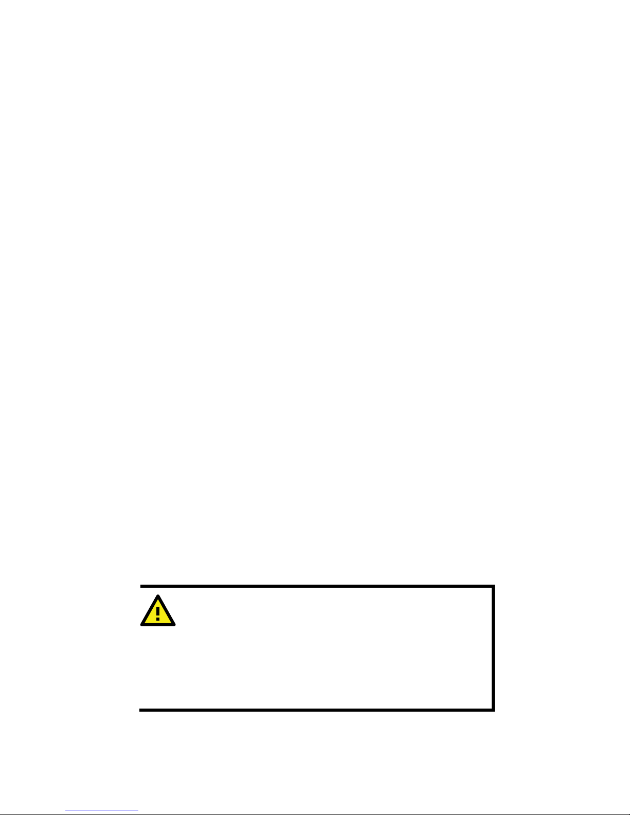
Serial Console Connection
The WAC-2004 offers one serial port with DB9 male connector for its
console access. The pin assignments are shown in the following table:
Pin
RS-232
1
DCD
2
RxD
3
TxD
4
DTR
5
GND
6
DSR
7
RTS
8
CTS 9 --
NOTE
The pin numbers for the male DB9 connectors, and hole numbers
for the female DB9 connectors are labeled on the connector.
However, the numbers are typically very small, so you may need
to use a magnifying glass to see the numbers clearly.
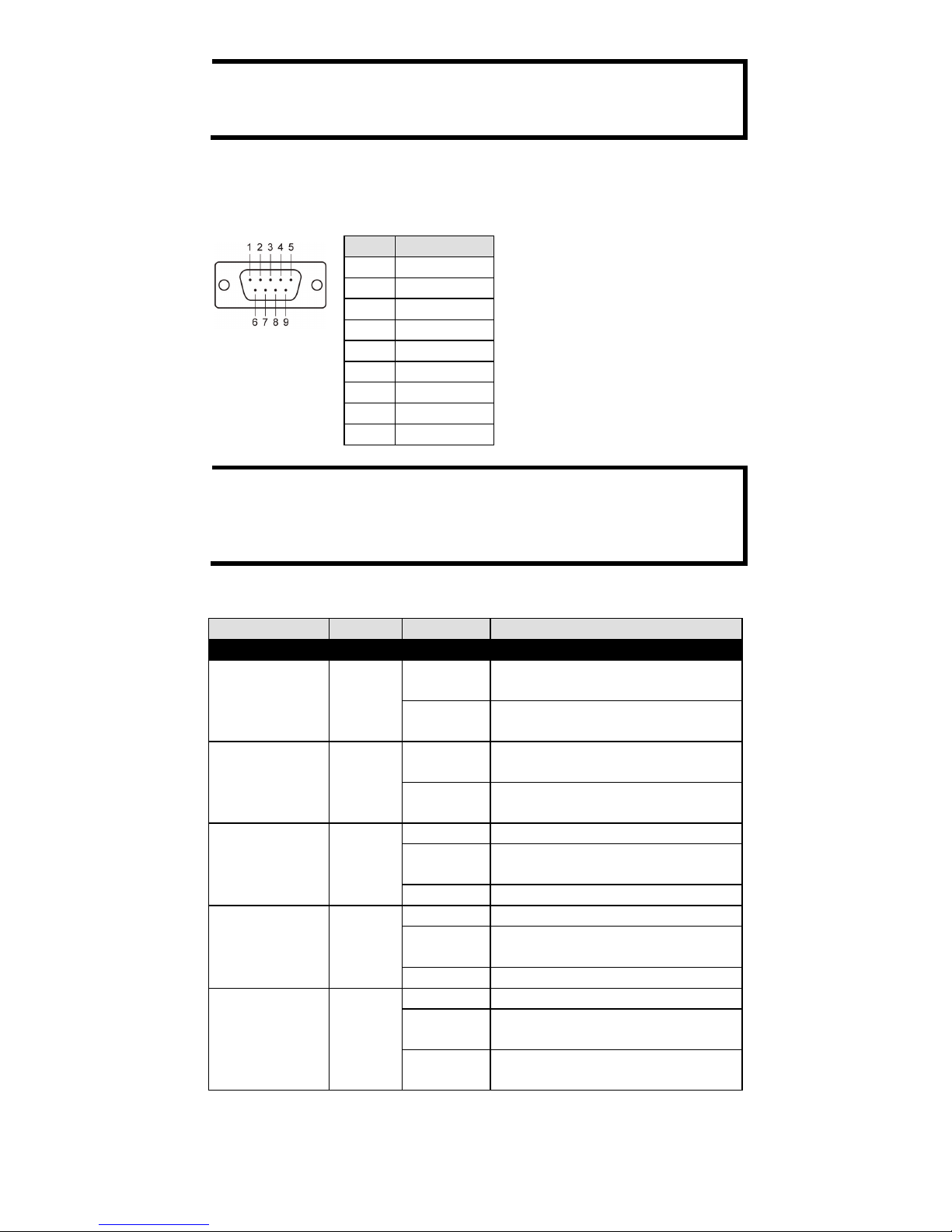
Front Panel LEDs
LED
Color
State
Description
Front Panel LED Indicators (System)
PWR1 Green
On
Power is being supplied from
power input 1.
Off
Power is not being supplied from
power input 1.
PWR2 Green
On
Power is being supplied from
power input 2.
Off
Power is not being supplied from
power input 2.
FAULT Red
On
Booting; System Error.
Blinking
(fast)
IP address conflict (interval: 0.5
sec).
Off
Normal status.
STATE
Green
/Red
Green
Software Ready
Green
(Blinking)
The WAC-2004 has been located
by Search Utility. (interval: 1sec)
Red
Booting error
Gigabit LAN
LEDs 1
(2-3 Reserved)
Green
/Amber
Green
100 Mbps Ethernet mode.
Amber
1000 Mbps (Gigabit) Ethernet
mode.
Off
No activity or 10 Mbps Ethernet
mode.
Page 7

- 7 -
Specifications
Technology
Standards IEEE 802.11i for Wireless Security
IEEE 802.3 for 10Base5
IEEE 802.3u for 100BaseT(X)
IEEE 802.3ab for 1000BaseT
Security
WPA/WPA2 (IEEE 802.1X/RADIUS, TKIP and
AES)
Protocol Support
General Protocols
ARP, DNS, HTTP, HTTPS, ICMP, IP, LLDP, Proxy
ARP, RADIUS, SMTP, SNMP, SNTP, SSH,
SYSLOG, TCP, TELNET, TFTP, UDP
Interface
AC Power Sockets
2 (C13-type)
Console
1, RS-232 (DB9-type, male)
LAN Port (LAN1)
1, 10/100/1000BaseT(X), auto negotiation
speed (RJ45-type)
LAN Port (LAN 2-4)
3, Reserved for future expansion (RJ45-type)
LED Indicators
PWR1, PWR2, FAULT, STATE, LAN 100M/1000M
Power Requirements
Input Voltage
Dual AC inputs, 100 to 240 VAC/VDC
auto-ranging, 47 to 63 Hz
Connector
C13
Physical Characteristics
Housing
SECC sheet metal (1 mm)
Dimensions
325 x 440 x 44 mm (12.80 x 17.32 x 1.73 in)
(without rackmount ears)
Weight
5.48 Kg
Installation
Standard 19-inch rackmounting
Environmental Limits
Operating Temperature
Standard models: 0 to 50°C (32 to 122°F)
Storage Temperature
-40 to 85°C (-40 to 185°F)
Ambient Relative
Humidity
5 to 95% (non-condensing)
Regulatory Approvals*
Safety
UL 60950-1
EMC
EN 55022 Class A, EN 61000-3-2, EN 61000-3-3,
EN 55024, FCC Part 15 Subpart B Class A
Green Product
RoHS, CRoHS, WEEE
*Please check Moxa’s website for the most up-to-date certification status.
WARRANTY
3 years
See http://www.moxa.com/warranty
ATTENTION
The WAC
-2004 is NOT
designed for use by the general public. A
well-trained technician is required to safely deploy the WAC-2004
Page 8

- 8 -
Technical Support Contact Information
www.moxa.com/support
Moxa Americas:
Toll
-free: 1-888-669-2872
Tel:
+1-714-528-6777
Fax:
+1-714-528-6778
Moxa China (Shanghai office):
Toll
-free: 800-820-5036
Tel:
+86-21-5258-9955
Fax:
+86-21-5258-5505
Moxa Europe
:
Tel:
+49-89-3 70 03 99-0
Fax:
+49-89-3 70 03 99-99
Moxa Asia
-Pacific:
Tel:
+886-2-8919-1230
Fax:
+886-2-8919-1231
 Loading...