

Page 1

2014 Moxa Inc. All rights reserved.
Reproduction without permission is prohibited.
P/N: 1802010010011
WAC-1001 Series
Quick Installation Guide
Second Edition, May 2014
Page 2

- 2 -
Overview
The goal of zero-latency-roaming is to allow clients to seamlessly
maintain their communications as they move from one access point to
another. Moxa’s next generation Turbo Roaming technology together
with the WAC-1001 enables 50 ms roaming for enabled AWK-RTG series
devices. This advanced roaming technology delivers high-speed, secure
handoffs within the same subnet and enables clients to roam between APs
in under 50 milliseconds while upholding stringent security in extremely
demanding environments. The WAC-1001 is rated to operate at
temperatures of 0 to 60°C for standard models and -40 to 75°C for
extended temperature models, and is rugged enough for on-site
installation in any harsh industrial environment.
Package Checklist
The WAC-1001 series wireless controller is shipped with the following
items. If any of these items are missing or damaged, please contact your
customer service representative.
• WAC-1001 series wireless controller
• 1 cable holder with 1 screw
• 2 protective caps
• Wall mount kit
• Quick installation guide
• Software CD
• Warranty card
Installation and Configuration
Before installing the WAC-1001, verify that all items in the Package
Checklist are in the box.
Note that the WAC-1001 must be configured before use. Refer to the
WAC-1001 Series User’s Manual for more details.
The WAC-1001 has a default IP address of 192.168.127.253, which you
must use when connecting to the device for the first time. When
configuring the WAC-1001 for the first time, use the following default user
name and password:
User name: admin
Password: root
ATTENTION
For security reasons, we strongly recommend changing the
default
password. To do so, select Maintenance Password
,
and then follow the on
-screen instructions.
To make the change
s effective, you must click Save
Configuration
to save the changes (Restart to apply the
changes).
Page 3
- 3 -
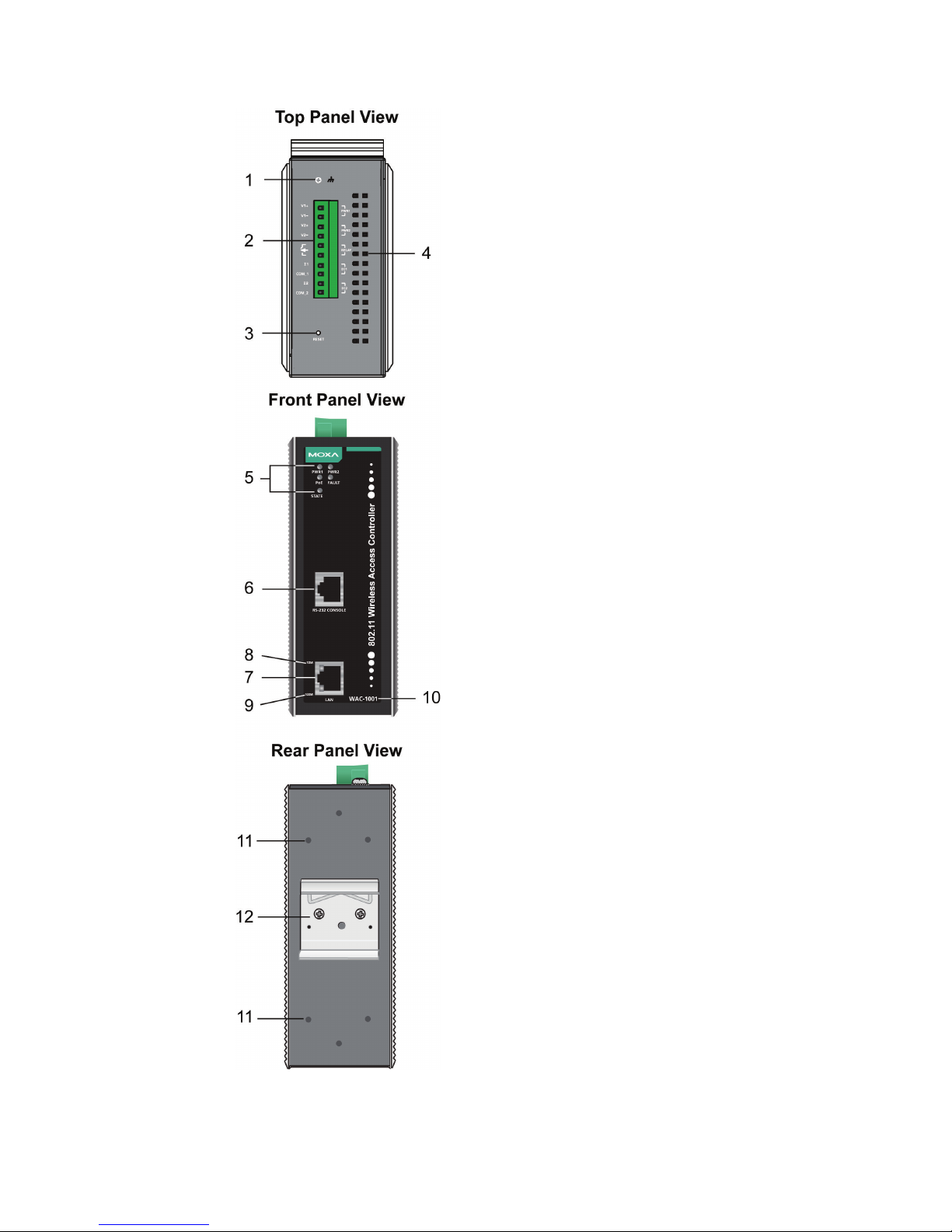
Panel Layout of the WAC-1001 Series
1. Grounding screw
2.
Terminal block for PWR1, PWR2,
relay, DI1, and DI2
3. Reset button
4. Heat dissipation orifices
5.
System LEDs: PWR1, PWR2, PoE,
FAULT, and STATE LEDs
6. RS-232 console port
7. 10/100BaseT(X) RJ45 Port
8. 10M LED
9. 100M LED
10.
Model name
11.
Screw hole for wall mounting kit
12.
DIN-Rail mounting kit
Page 4

- 4 -
Mounting Dimensions
DIN-Rail Mounting
The aluminum DIN-Rail attachment plate should already be fixed to the
back panel of the WAC-1001 when you take it out of the box.
If you need to reattach the DIN-Rail attachment plate to the WAC-1001,
make sure the stiff metal spring is situated towards the top as shown in
the figures below.
How to Mount the WAC-1001
STEP 1:
Insert the top of the
DIN-Rail into
the slot just
below the stiff metal
spring.
STEP 2:
Push down to snap the unit into
place.
To remove the WAC-1001 from the DIN-Rail, simply reverse steps 1 and
2.
Page 5

- 5 -
Wall Mounting
For added convenience, the WAC-1001 can be wall mounted as illustrated
below.
STEP 1:
Remove the aluminum DIN
-Rail
attachment plate from the
WAC-1001
,
and then attach the wall mount plates
with M3 screws, as shown
on the right
.
STEP 2:
Mounting the
WAC-1001 to a wall requires 4 screws. Us
e
the
WAC-1001, with wall mount plates attached, as a
guide to mark the correct locations
for the 4 screws.
The
heads of the screws should be less than 6.0 mm in
diameter, and the shafts should be less than 3.5 mm in
diameter, as shown on the right.
Do not screw the screws in all the way—leave a space of about 2 mm to
allow room for sliding the wall mount panel between the wall and the
screws.
NOTE
Test the screw’s head and shank size by inserting the screw into
one of the keyhole
-shaped apertures of the wall mounting
plates
before screwing it into the wall.
STEP 3:
After
the screws are fixed into
the wall, insert the four screw
heads through the large opening
of the keyhole
-shaped
apertures, and then slide the
WAC
-1001 downwards, as
indicated
on the right. Tighten
the four screws for added
stability.
Page 6

- 6 -
Wiring Requirements
WARNING
Safety First!
Be sure the power cord
is disconnected before installing and/or
wiring your WAC-1001.
WARNING
Safety
First!
Calculate the maximum possible current in each power wire and
common wire. Observe all electrical codes dictating the
maximum current allow
ed for each wire size.
If the current goes above the maximum rating, the wiring could
overheat, causing serious damage to your equipment.
You should also pay attention to the following:
• Use separate paths to route wiring for power and devices. If power
wiring and device wiring paths must cross, make sure the wires are
perpendicular at the intersection point.
NOTE: Do not run signal or communications wiring and power wiring
in the same wire conduit. To avoid interference, wires with different
signal characteristics should be routed separately.
• You can use the type of signal transmitted through a wire to
determine which wires should be kept separate. As a rule of thumb,
wiring with similar electrical characteristics can be bundled together.
• Keep input wiring and output wiring separate.
• It is strongly advised that you label wiring to all devices in the system.
ATTENTION
This product is intended to be supplied by a Listed Power Unit
marked “Class 2” or “LPS” and rated O/P: 12 to 48 VDC
Grounding the WAC-1001
Grounding and wire routing help limit the effects of noise due to
electromagnetic interference (EMI). Run the ground wire from the ground
screw to the grounding surface prior to connecting devices.
ATTENTION
This product is
to be mounted to a well-grounded mounting
surface, such as a metal panel.
Page 7

- 7 -
Wiring the Redundant Power Inputs
Two pairs of contacts of the 10-contact terminal block connector on the
WAC-1001’s top panel are used for the WAC-1001’ two DC inputs. Top
and front views of the terminal block connector are shown here.
STEP 1:
Insert the negative/positive DC wires into the
V
-/V+ terminals.
STEP 2:
To keep the DC wires from pulling
loose
, use a
small flat
-blade screwdriver to tighten the
wire
-clamp
screws on the front of the terminal
block connector.
STEP 3:
Insert the plastic terminal block connector
prongs into the terminal block receptor, which
is
located on the WAC-1001’s top panel.
ATTENTION
Before connecting
the WAC-1001
to the DC power inputs, make
sure the DC power source voltage is stable.
Wiring the Relay Contact
The WAC-1001 has one relay output, which consists of two contacts of the
terminal block on the WAC-1001’s top panel. Refer to the previous section
for detailed instructions on how to connect the wires to the terminal block
connector and how to attach the terminal block connector to the terminal
block receptor. These relay contacts are used to indicate user-configured
events. The two wires attached to the relay contacts form an open circuit
when a user-configured event is triggered. If a user-configured event
does not occur, the relay circuit will remain closed.
Wiring the Digital Inputs
The WAC-1001 has two sets of digital inputs—DI1 and DI2. Each DI
consists of two contacts from the 10-pin terminal block connector. Refer
to the “Wiring the Redundant Power Inputs” section for detailed
instructions on how to connect the wires to the terminal block connector,
and how to attach the terminal block connector to the terminal block
receptor.
Page 8

- 8 -
Cable Holder Installation (Optional)
You may choose to attach the cable holder to the bottom of the
WAC-1001. This helps to keep cabling neat and avoid accidents caused
from cluttered cables.
STEP 1:
Screw the cable holder onto the bottom of the
WAC
-1001.
STEP 2:
After mounting the WAC-1001 and plugging in the LAN cable,
fasten
the cable along the device and wall.
Pin Assignments
10/100BaseT(X) Ethernet Port Connection
The 10/100BaseT(X) ports located on the WAC-1001’s front panel are
used for connecting Ethernet-enabled devices.
Below are the pinouts for both MDI (NIC-type) ports and MDI-X
(HUB/Switch-type) ports.
MDI Port Pinouts
MDI-X Port Pinouts
8-pin RJ45
Pin
Signal
Pin
Signal
1
Tx+
1
Rx+
2
Tx- 2 Rx-
3
Rx+
3
Tx+
6
Rx- 6 Tx-
DB9 Male (RS-232) Port Pinouts
The WAC-1001 has one RS-232 (8-pin RJ45) console port located on its
front panel. Use either an RJ45-to-DB9 or RJ45-to-DB25 cable to connect
the WAC-1001’s console port to your PC’s COM port. You may then use a
console terminal program to access the WAC-1001 for console
configuration.
Page 9

- 9 -
Console Pinouts for 10-pin or 8-pin RJ45
10-Pin
Description
8-Pin 1 -----
2 DSR
1 3 RTS
2
4
GND
3
5
TxD
4
6
RxD
5
7
DCD
6
8
CTS
7
9
DTR
8
10
-----
NOTE
1. The pin numbers for the male DB9 and DB25 connectors,
and hole numbers for the
female DB9 and DB25 connectors
are labeled on the connector. However, the numbers are
typically very small, so you may need to use a magnifying
glass to see the numbers clearly.
2. The pin numbers for both the 8-pin and 10-pin RJ45
connectors (and ports) are typically not labeled on the
connector (or port). Refer to the pinout diagram above to
see how the RJ45’s pins are numbered.
Front Panel LEDs
The WAC-1001’s front panel has seven LED indicators, refer to the
following table for details.
LED
Color
State
Description
Front Panel LED Indicators (System)
PWR1 Green
On
Power is being supplied from power
input 1.
Off
Power is not being supplied from power
input 1.
PWR2 Green
On
Power is being supplied from power
input 2.
Off
Power is not being supplied from power
input 2.
PoE Amber
On
Power is being supplied via PoE.
Off
Power is not being supplied via PoE.
FAULT Red
On
Booting; System Error; Relay is on.
Blinking
(slow)
IP address cannot be obtained from
DHCP server (interval: 1 sec).
Blinking
(fast)
IP address conflict (interval: 0.5 sec).
Off
Normal status.
STATE
Green
/Red
Green
Software Ready
Green
(Blinking)
The WAC-1001 has been located by
Search Utility. (interval: 1sec)
Red
Booting error
Page 10

- 10 -
LED
Color
State
Description
TP Port LED Indicators (Port Interface)
100M Green
On
TP port’s 100Mbps link is active
Blinking
Data is being transmitted at 100 Mbps
Off
TP port’s 100Mbps link is inactive.
10M Amber
On
TP port’s 10Mbps link is active.
Blinking
Data is being transmitted at 10 Mbps
Off
TP port’s 10Mbps link is inactive.
Specifications
WLAN Interface
Standards
IEEE 802.11i for Wireless Security
IEEE 802.3u 10/100BaseT(X) for Ethernet LAN
IEEE 802.3af for Power-over-Ethernet
Security
WPA /WPA2 (IEEE 802.1X/ RADIUS, TKIP and
AES)
Interface
Connection
10-pin removable terminal block
Alarm Contact
1 relay output (1 A @ 24 VDC)
Digital Input 2 electrically-isolated inputs
+3 to -30 V for state “0” (OFF)
+13 to +30 V for state “1” (ON)
Max. input current: 8 mA
Console
RS-232 (RJ45 type)
LAN Port
10/100BaseT(X) auto negotiation speed
LED Indicators
PWR1, PWR2, PoE, FAULT, STATE
Power Requirements
Input Voltage
12 to 48 VDC, redundant dual DC power inputs or
48 VDC Power-over-Ethernet (IEEE 802.3af)
Connector
10-pin removable terminal block
Reverse Polarity
Protection
Present
Physical Characteristics
Housing
Aluminum, providing IP30 protection
Dimensions
53.6 x 135 x 105 mm (2.11 x 5.31 x 4.13 in)
Weight
700 g
Installation
DIN-Rail, wall mounting (with optional kit)
Environmental Limits
Operating Temperature
Standard models: 0 to 60°C (32 to 140°F)
Wide Temp. Models: -40 to 75°C (-40 to 167°F)
Storage Temperature
-40 to 85ºC (-40 to 185ºF)
Ambient Relative
Humidity
5 to 95% (non-condensing)
Regulatory Approvals*
Safety
EN 60950-1, UL60950-1
EMC
FCC Part 15 Subpart B Class B, EN 55022/55024
*Please check Moxa’s website for the most up-to-date certification status.
WARRANTY
5 years
See http://www.moxa.com/warranty
Page 11

- 11 -
ATTENTION
The
WAC-1001 is NOT a portable mobile device and should be
located
at least 20 cm away from the human body.
The
WAC-1001 is NOT designed for use by the general public.
A
well
-trained technician is required to safely deploy the WAC-
1001
and establish a secure wireless network.
Technical Support Contact Information
www.moxa.com/support
Moxa Americas:
Toll
-free: 1-888-669-2872
Tel:
1-714-528-6777
Fax:
1-714-528-6778
Moxa China (Shanghai office):
Toll
-free: 800-820-5036
Tel:
+86-21-5258-9955
Fax:
+86-21-5258-5505
Moxa Europe
:
Tel:
+49-89-3 70 03 99-0
Fax:
+49-89-3 70 03 99-99
Moxa
Asia-Pacific:
Tel:
+886-2-8919-1230
Fax:
+886-2-8919-1231
 Loading...