

Page 1
— 1 — — 2 — — 3 —
W311/321-LX
Quick Installation Guide
Third Edition, January 2009
1. Overview
The W311/321 embedded computers have 1 or 2 RS-232/422/485 serial
ports, one 10/100 Mbps Ethernet port, an embedded wireless LAN card,
an SD socket interface for storage expansion, making the W311/321
ideal for your wireless embedded applications.
2. Package Checklist
Before installing the W311/321, please verify that the package contains
the following items:
y 1 W311/321 embedded computer
y Quick Installation Guide
y Document & Software CD
y Ethernet cross-over cable: RJ45 to RJ45, 100 cm
y Console port cable:
CBL-4PINDB9F-100: 4-pin header to DB9 (Female) cable, 100 cm
y Universal Power Adaptor
y Product Warranty Booklet
Notify your sales representative if any of the above items are missing or
damaged.
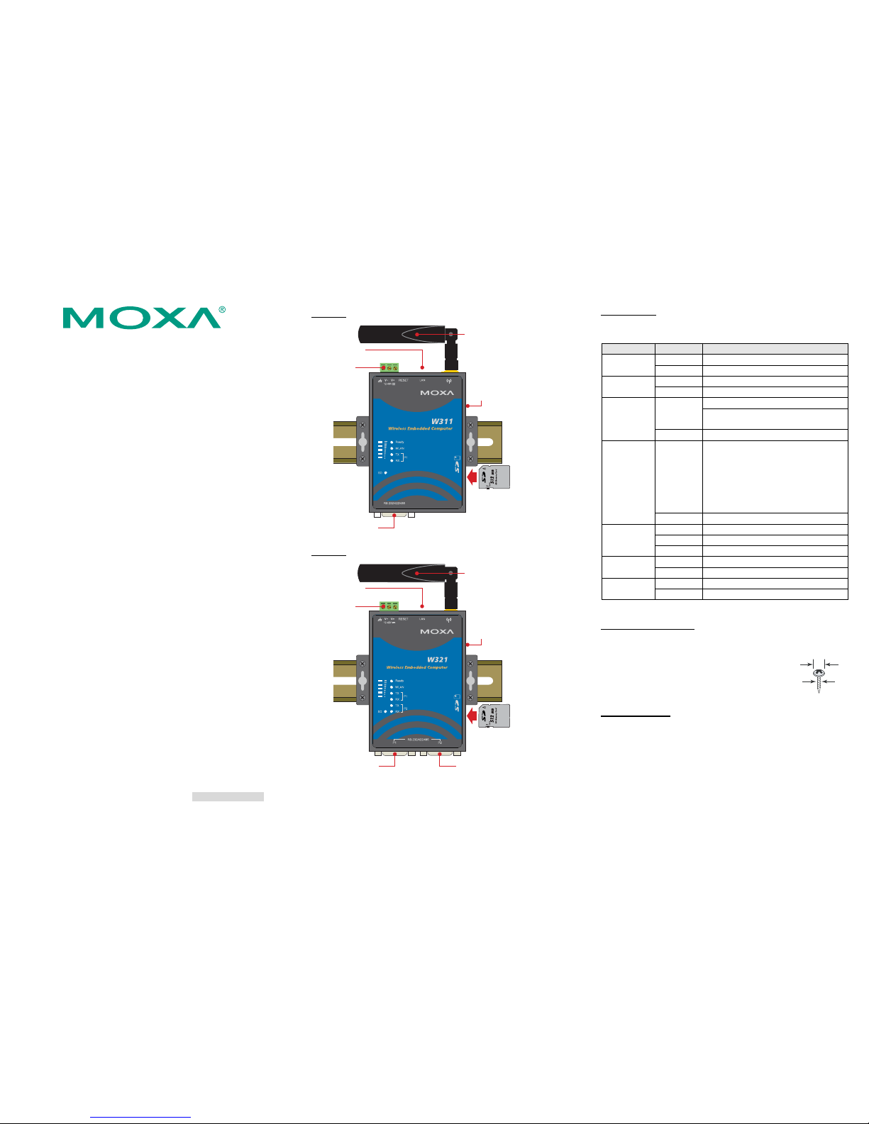
3. W311/321 Panel Layout
The W311/321 comes with one or two RS-232/422/485 serial ports,
one RS-232 console port, one 10/100 Mbps LAN port, and an
embedded wireless LAN card. The following figures show the panel
layouts of the W311/321.
W311-LX
Ethernet
(10/100BaseTx)
24 VDC
Wireless LAN
antenna
Internal SD Slot for
Storage Expansion
(remove cover to access)
Serial Port
(RS-232/422/485)
Serial
console port
P1
W321-LX
Ethernet
(10/100BaseTx)
12 to
48 VDC
Wireless LAN
antenna
Internal SD Slot for
Storage Expansion
(remove cover to access)
Serial Port 2
(RS-232/422/485)
Serial Port 1
(RS-232/422/485)
Serial
console port
LED Indicators
The following table describes the LED indicators located on the front
panel of the W311/321.
LED Name LED Color LED Function
Green Power is on and functioning normally.
Ready
Off Power is off, or power error exists
Green SD card detected
SD
Off No SD card detected
ON: WLAN is ready
Green
Blinking: WLAN IP conflict or DHCP
server not responding.
WLAN
Off Console port is transmitting TX data
Green
Number of glowing LEDs indicates signal
strength:
5: Excellent
4: Very good
3: Good
2: Fair
1: Bad
Signal
Strength
(5 LEDs)
Off No signal or WLAN connection failed
Orange 10 Mbps Ethernet link
Green 100 Mbps Ethernet link
LAN
Off Disconnected or short circuit
Green Serial port (1 or 2) transmitting data. TxD
(P1/P2)
Off Serial port (1 or 2) not transmitting data.
Yellow Serial port (1 or 2) receiving data. RxD
(P1/P2)
Off Serial port (1 or 2) not receiving data.
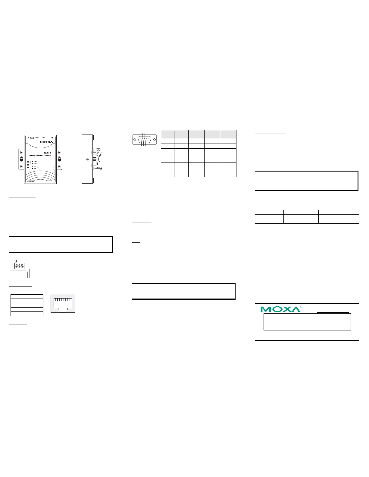
4. Installing the W311/321
Wall or Cabinet Mounting
The W311/321 have built-in “ears” for attaching the embedded
computers to a wall or the inside of a cabinet. We
suggest using two screws per ear to attach the
W311/321 to a wall or cabinet. The heads of the
screws should be less than 6.0 mm in diameter, and
the shafts should be less than 3.5 mm in diameter, as
shown by the figure at the right.
DIN-Rail Mounting
DIN-rail attachments can be purchased separately to attach the product to
a DIN-rail. When snapping the attachments to the DIN-rail, make sure
that the stiff metal springs are at the top.
P/N: 1802003116012
mm 0.6
mm 5.3
Page 2
— 4 — — 5 — — 6 —
Wall or Mounting DIN-Rail Mounting
SD
P1
5. Connector Description
Power Connector
Connect the 12 to 48 VDC LPS or Class 2 power line to the ThinkCore
W311/321’s terminal block. If the power is properly supplied, the Power
LED will light up. The OS is ready when the Ready LED glows a solid
green.
Grounding the W311/321
Grounding and wire routing help limit the effects of noise due to
electromagnetic interference (EMI). Run the ground connection from the
ground screw to the grounding surface prior to connecting the power.
ATTENTION
This product is intended to be mounted to a well-grounded mounting
surface, such as a metal panel.
SG
SG: The Shielded Ground (sometimes called Protected
Ground) contact is the left most contact of the 3-pin
power terminal block connector when viewed from
the angle shown here. Connect the SG wire to an
appropriate grounded metal surface.
Ethernet Ports
The 10/100 Mbps Ethernet port uses RJ45 connectors.
Pin Signal
1 ETx+
2 ETx3 ERx+
6 ERx-
81
Serial Ports
The serial ports use DB9 connectors. Each port can be configured by
software for RS-232, RS-422, or RS-485. The pin assignments for the
ports are shown in the following table:
54321
9876
Pin RS-232 RS-422
RS-485
(4-wire)
RS-485
(2-wire)
1 DCD TxDA(-) TxDA(-) --2 RxD TxDB(+) TxDB(+) --3 TxD RxDB(+) RxDB(+) DataB(+)
4 DTR RxDA(-) RxDA(-) DataA(-)
5 GND GND GND GND
6 DSR --- --- --7 RTS --- --- --8 CTS --- --- ---
SD Slot
The W321 has an internal SD slot for storage expansion. The SD slot
allows users to plug in a Secure Digital (SD) memory card compliant
with the SD 1.0 standard for up to 1 GB of additional memory space. To
install an SD card, first use a screw driver to remove the SD slot cover to
access the slot. The slot is located on the right panel of the W321. Plug
the SD card directly into the socket, and then replace the SD slot cover.
The SD card will be mounted at /mnt/sd. To remove the SD card from the
slot, press the SD card in slightly with your finger, and then remove your
finger to cause the card to spring out partially. You may now grasp the
top of the card with two fingers and pull it out.
Console Port
The serial console port is a 4-pin pin-header RS-232 port. It is designed
for serial console terminals, which are useful for viewing boot-up
messages. Use the CBL-4PINDB9F-100 cable included with the product
to connect a PC to the W311/321’s serial console port.
Reset
Press the “Reset ” button and hold it in for at least 5 seconds to load the
factory default configuration. After the factory default configuration has
been loaded, the system will reboot automatically. The Ready LED will
blink on and off for the first 5 seconds, and then maintain a steady glow
once the system has rebooted.
Real-time Clock
The W311/321’s real-time clock is powered by a lithium battery. We
strongly recommend that you do not replace the lithium battery without
help from a qualified Moxa support engineer. If you need to change the
battery, contact the Moxa RMA service team.
ATTENTION
There is a risk of explosion if the battery is replaced by an incorrect
type of battery.
6. Powering on the W311/321
To power on the W311/321, connect the “terminal block to power jack
converter” to the W311/321’s DC terminal block (located on the left rear
panel), and then connect the power adapter. Note that the Shielded
Ground wire should be connected to the right most pin of the terminal
block. It takes about 30 seconds for the system to boot up. Once the
system is ready, the Ready LED will light up.
Power Consumption
• W311: 400 mA @ 12 VDC
• W321: 400 mA @ 12 VDC
7. Connecting the W311/321 to a PC
There are two ways to connect the W311/321 to a PC: (1) through the
serial console port, or (2) by Telnet over the network. The COM settings
for the serial console port are: Baudrate=115200 bps, Parity=None,
Data bits=8, Stop bits =1, Flow Control=None.
ATTENTION
Use the CBL-4PINDB9F-100 cable included with the product to
connect a PC to the W311/321’s serial console port. Remember to
choose “VT100” terminal type.
To use Telnet, you need to know the W311/321’s IP address and netmask.
The default LAN settings are shown below. For first-time configuration,
you may find it convenient to use a cross-over Ethernet cable to connect
directly from the PC to the W311/321.
Default IP Address Netmask
LAN 1 192.168.3.127 255.255.255.0
LAN 2(wireless) 192.168.4.127 255.255.255.0
Once the W311/321 is powered on, the Ready LED will light up, and a
login page will open. Use the following default Login name and
Password to proceed. The defaults are:
Login: root
Password: root
8. Configuring the Ethernet Interface
Type the command vi rc to invoke VI Editor. The default IP addresses for
W321/311’s Ethernet LAN and Wireless LAN are:
ifconfig eth0 192.168.3.127
ifconfig eth1 192.168.4.127
NOTE: Refer to the W311/321 User’s Manual for information on how to
configure the WLAN interface, and for other configuration information.
Click here for online support:
www.moxa.com/support
The Americas: +1-714-528-6777 (toll-free: 1-888-669-2872)
Europe: +49-89-3 70 03 99-0
Asia-Pacific: +886-2-8919-1230
China: +86-21-5258-9955 (toll-free: 800-820-5036)
© 2009 Moxa Inc. All rights reserved.
Reproduction without permission is proh ibited.
 Loading...