

Moxa Technologies VPort P06-2L36M, VPort P06-2M25M, VPort P06-2L60M, VPort P06-2L80M, VPort P06-2L42M Quick Installation Manual
...Page 1

P/N: 1802000062010
*1802000062010*
VPort 06-2 Series
Quick Installation Guide
MOXA IP Camera
Edition 1.1, December 2015
Technical Support Contact Information
www.moxa.com/support
Moxa Americas:
Toll
-free: 1-888-669-2872
Tel:
1-714-528-6777
Fax:
1-714-528-6778
Moxa China (Shanghai office):
Toll
-free: 800-820-5036
Tel:
+86-21-5258-9955
Fax:
+86-21-5258-5505
Moxa Europe:
Tel:
+49-89-3 70 03 99-0
Fax:
+49-89-3 70 03 99-99
Moxa Asia-Pacific:
Tel:
+886-2-8919-1230
Fax:
+886-2-8919-1231
Moxa India:
Tel:
+91-80-4172-9088
Fax:
+91-80-4132-1045
2015 Moxa Inc. All rights reserved.
Page 2

- 2 -
Overview
The VPort 06-2 series is a compact IP dome camera that supports FHD
(1080P, 1920 x 1080) video image and H.264/MJPEG. It is designed for
mobile video surveillance applications and features EN 50155 compliance,
vandal-proofing (EN 62262 IK8), operating t emperature of -25 to 55°C or
-40 to 70°C (T model), rugged M12 Ethernet port, 1 a udio input or built-in
microphone, PoE or 24 VDC powe r inputs, I P66 ra in and dust protect ion,
dehumidifying membrane, and selectable lens models, for the versatility
and ruggedness required to excel in many different installations and
environments for mobile IP video surveillance a pplications.
Ordering Information
The following VPort 06-2 series models are available:
Model
Lens
(mm)
Audio
Temperature
Conformal
Coating
PoE model 24 VDC model
-25 to
55°C
-40 to
70°C
VPort P06-2L25M VPort 06-2L25M 2.5 Line-in
– –
VPort P06-2L36M VPort 06-2L36M 3.6 Line-in
– –
VPort P06-2L42M VPort 06-2L42M 4.2 Line-in
– –
VPort P06-2L60M VPort 06-2L60M 6 Line-in
– –
VPort P06-2L80M VPort 06-2L80M 8 Line-in
– –
VPort P06-2M25M VPort 06-2M25M 2.5 Mic-in
– –
VPort P06-2M36M VPort 06-2M36M 3.6 Mic-in
– –
VPort P06-2M42M VPort 06-2M42M 4.2 Mic-in
– –
VPort P06-2M60M VPort 06-2M60M 6 Mic-in
– –
VPort P06-2M80M VPort 06-2M80M 8 Mic-in
– –
VPort P06-2L25M-T VPort 06-2L25M-T 2.5 Line-in –
–
VPort P06-2L36M-T VPort 06-2L36M-T 3.6 Line-in –
–
VPort P06-2L42M-T VPort 06-2L42M-T 4.2 Line-in –
–
VPort P06-2L60M-T VPort 06-2L60M-T 6 Line-in –
–
VPort P06-2L80M-T VPort 06-2L80M-T 8 Line-in –
–
VPort P06-2M25M-T VPort 06-2M25M-T 2.5 Mic-in –
–
VPort P06-2M36M-T VPort 06-2M36M-T 3.6 Mic-in –
–
VPort P06-2M42M-T VPort 06-2M42M-T 4.2 Mic-in –
–
VPort P06-2M60M-T VPort 06-2M60M-T 6 Mic-in –
–
VPort P06-2M80M-T VPort 06-2M80M-T 8 Mic-in –
–
VPort P06-2L25M-CT VPort 06-2L25M-CT 2.5 Line-in
–
VPort P06-2L36M-CT VPort 06-2L36M-CT 3.6 Line-in
–
VPort P06-2L42M-CT VPort 06-2L42M-CT 4.2 Line-in
–
VPort P06-2L60M-CT VPort 06-2L60M-CT 6 Line-in
–
VPort P06-2L80M-CT VPort 06-2L80M-CT 8 Line-in
–
VPort P06-2M25M-CT VPort 06-2M25M-CT 2.5 Mic-in
–
VPort P06-2M36M-CT VPort 06-2M36M-CT 3.6 Mic-in
–
VPort P06-2M42M-CT VPort 06-2M42M-CT 4.2 Mic-in
–
VPort P06-2M60M-CT VPort 06-2M60M-CT 6 Mic-in
–
VPort P06-2M80M-CT VPort 06-2M80M-CT 8 Mic-in
–
VPort P06-2L25M-CT-T VPort 06-2L25M-CT-T 2.5 Line-in –
VPort P06-2L36M-CT-T VPort 06-2L36M-CT-T 3.6 Line-in –
VPort P06-2L42M-CT-T VPort 06-2L42M-CT-T 4.2 Line-in –
VPort P06-2L60M-CT-T VPort 06-2L60M-CT-T 6 Line-in –
VPort P06-2L80M-CT-T VPort 06-2L80M-CT-T 8 Line-in –
Page 3
- 3 -
Model
Lens
(mm)
Audio
Temperature
Conformal
Coating
PoE model 24 VDC model
-25 to
55°C
-40 to
70°C
VPort P06-2M25M-CT-T VPort 06-2M25M-CT-T 2.5 Mic-in –
VPort P06-2M36M-CT-T VPort 06-2M36M-CT-T 3.6 Mic-in –
VPort P06-2M42M-CT-T VPort 06-2M42M-CT-T 4.2 Mic-in –
VPort P06-2M60M-CT-T VPort 06-2M60M-CT-T 6 Mic-in –
VPort P06-2M80M-CT-T VPort 06-2M80M-CT-T 8 Mic-in –
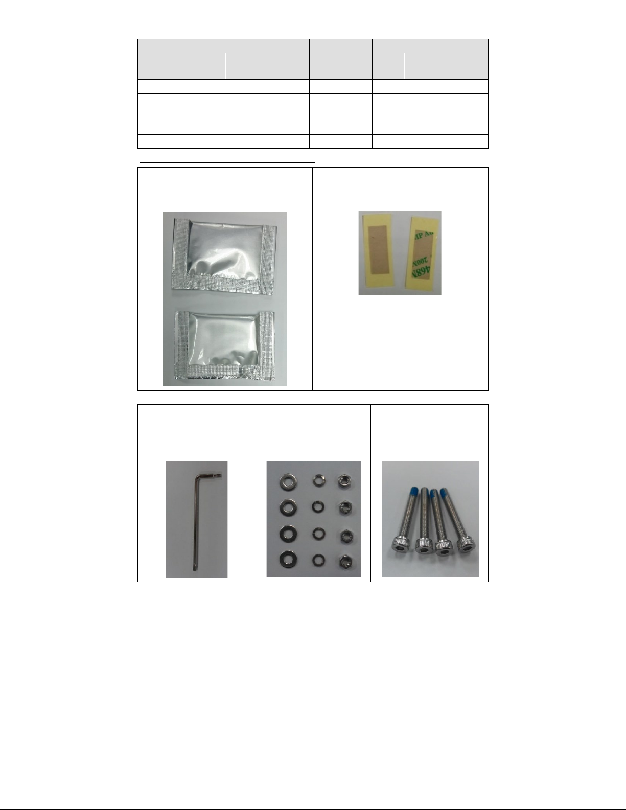
Screw handle accessory package
Two dry packs (sealed in sachets)
for absorbing moisture from the
inside of the camera.
Two double-
sided tapes for sticking
dry packs inside the camera.
Torx screwdriver for
attaching/detaching
the upper case.
4 sets of nut, gasket,
and spring washer for
mounting the camera.
4 indented hexagonal
head tapping screws for
mounting the camera
on the ceiling.
Page 4
- 4 -
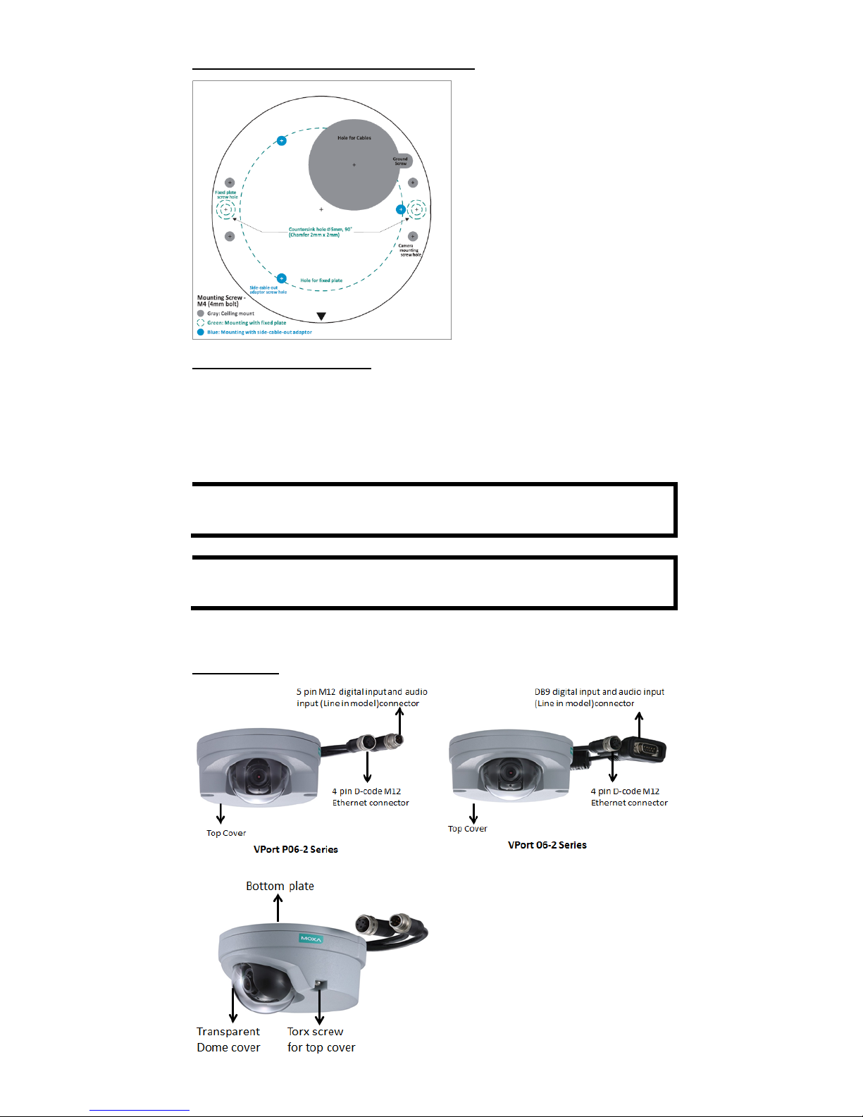
Sticker for camera mounting positions
Contents of the Package
• Quick Installation Guide
• Two dry packs and double sided tape
• Documentation and Software CD (includes User’s Manual, Quick
Installation Guide, and VPort Utility)
• Warranty card
NOTE
Check the model name on the VPort’s side labe l to deter mine if it
is the correct one for your order.
NOTE
This product must be installed in compliance with your loca l laws
and regulations.
Product Description
Appearance
Page 5

- 5 -
•
4-pin D-code M12 Ethernet
connector: Can be used for both
the PoE power supply (PoE model)
and Auto MDI/MDI-X Ethernet
connection
NOTE
To connect the VPort 06/P06-2MP series to a network, use an
Ethernet cable with D
-code M12 connector and an M12 PoE
switch or RJ45 PoE switch
M12 D-code to M12 D-code
cable
M12 PoE switch (e.g.,
TN-5508-4PoE)
M12 D-code and RJ45 cable
RJ45 PoE switch
(e.g., EDS-P510)
NOTE
The power input rating of the PoE model is 48 VDC, 0.2 A, with
maximum power consumption
of approximately 8.1 W.
The power input rating of the DC model
s are 12
VDC, 0.86 A, with
maximum power consumption
of 10.2 W, and 24 VDC, 0.38 A
with maximum power consumption of 9.0 W.
NOTE
The equipment is designed for indoor installation only and is not
intended to be connected to exposed (outside the plant)
networks.
• DB9 connector (24 VDC model): Includes power input, digital
input signal, and audio input (line-in model).
PIN
Con.
1
24 VDC +
2
NA
3
Audio +
4
NA
5
DI +
6
24 VDC return
7
NC
8
Audio -
9
DI -
Page 6

- 6 -
• 5-pin M12 connector (PoE model): Includes digital input signal,
and audio input (line-in model).
PIN
Con.
1
DI +
2
Line-in+
3
DI -
4
Line-in -
5
NA
• Solid metal top cover: This top c over can be removed for adjusting
the camera lens position.
• Transparent dome cover: The VPort 06-2 series is designed w ith a
transparent PC dome cover, which is vandal-proof and satisfies EN
62262 (IEC 62262) Class IK8 requirements.
• 2 Torx screws for top cover: These 2 torx screws are des igned with
anti-shedding to make installation more convenient. Use the L-type
torx screwdriver to remove or attach the top cover.
• Built-in microphone: VPort 06-2-MIC series products have a
built-in microphone, and can simultaneously display or record live
video and audio.
NOTE
The color of the form factor can be customized based on your
installation environment. Please contact your Moxa sales
representative for customization service.
Inside the Camera
• Mounting screw holes: There are 4 mounting screw holes for
mounting the VPort 06/P06-2 series on the ceiling or the access ory.
• Screw for fixing the lens’s position: To adjust the position of the
lens, loosen the thumb screw, and then retighten it after you are done
with adjusting the position of the lens.
• Lens with fixed focal length: The VPort 06/P06-2 series includes
models with 3 different focal lengths. Choose the appropriate focal
length for your lens based on the viewing angle and object d istanc e .
• Hardware reset button: Use a pointed object to depress the reset
button to reboot or restore factory defaults.
Reboot: press the button one time.
Factory default: press the button and hold for at least 5 sec.
Page 7

- 7 -
• Calibration for rotating lens (0 to 360°): Rotate the lens to get
the optimal image. When done, mark the position of this calibration
for future placement or mass installation.
• Calibration for adjusting lens’s vertical position (0 to 90°):
After adjusting the lens’s vertical position, mark the position of this
calibration for future placement or mass installation.
• Calibration for adjusting lens’s horizontal position (±15°):
After adjusting the lens’s horizontal position, mark the position of this
calibration for future placement or mass installation.
Hardware Installation
Step 1: Open and remove the top cover.
Use the torx screwdriver to loosen the top cover screws.
Step 2: Use the markings on the installation sticker to position the drill bit
before drilling holes.
There are 3 types of installation.
a.
Mounting with 4 mounting screws
To mount the camera on the
ceiling, drill a hole through the
gray portion of the sticker and
then mount the camera with the
4 nut/gasket/spring
-washer
sets and the 4 indented
hexagonal head tapping
screws.
b.
Mounting with the side-cable-out adapter
Use the side-cable-out adapter
(VP
-SCO2) if your installation
requires the cable
–out on the
side. Drill a hole through the
blue portion of the sticker for
mounting the adaptor on the
surface with 3 nut/gasket/
spring
-washer sets and
indented hexagonal head
tapping screws. Then, mount
the VPort 06
-2 on the adapter
with 4 M4 screws, which are
provided in the VP
-SCO2’s
package.
VP-SCO2
Page 8

- 8 -
c.
Mounting with the fixed plate
If you cannot use the
nut/gasket/spring
-washer set
to mount the camera on your
ceiling, use the VP
-FP2 fixed
plate. Drill holes through the
green dotted-line and 4 camera
mounting screw
markings on
the sticker, and then
place
the
VP
-FP2 insi
de the hole. Use the
2 countersunk screws to mount
the VP
-SP2
. Finally, mount the
VPort 06/P06
-2 series on the
fixed plate with the 4 indented
hexagonal head tapping
screws.
VP-FP2
NOTE
The screw hole for mounting the VP
-FP2 fixed plate is a
countersi
nk hole with 5 mm diameter, and 90° 2 x 2 mm
chamf
er. Take this into consideration when
drilling these 2 screw
holes.
Step 3: Connect the camera with the 4-pin M12 D-code Ethernet
connector and DB9 / 5-pin M12 connector.
NOTE
Connectors used with the cameras should be IP66 compliant.
Page 9

- 9 -
Step 4: Loosen the screw for
adjust
ing the horizontal, vertical,
and rotating lens position. Once the
lens position is correct, fix the screw.
Step 5:
Stick the double-
sided tapes
onto
two dry packs
and use the other
side of the tapes to s
tick the dry
pa
cks on the inside of
the top cover
to absorb the moisture
that might
have
entered the camera housing
during installation.
Step 6: Fix the top cover. The installation is now complete.
NOTE
1. The dry packs may become saturated if exposed to the air for
too long; for this reason, reattach the top cover
immediately
after sticking the dry packs inside the top cover.
If the cover
is removed at any time in the future, be sure to replace
the
dry packs before reattaching the cover.
2.
Make sure the top cover is attached tightly (place the
screws
in the holes such that they can stay unaided and tighten
all of
them. Retighten the screws in succession until they are all
completely tightened.)
3.
For the model with a
microphone, be careful not to damage
the metal spring on the small board mounted on the top
cover.
Software Installation
Step 1: Configure the VPort 06-2’s IP address.
When the VPort 06-2 series is first powered on, the POST (Power On Self
Test) will run for a few moments (about 30 seconds). The network
environment determines how the IP address is assigned.
Network Environment with DHCP Server
For this network environment, the unit’s IP address will be assigned by
the network’s DH CP server. Refer t o the DHCP server’s IP address table to
determine the unit’s assigned IP address. You may also use the Moxa
VPort and EtherDevice Configurator Utility (edscf g ui.exe), as descr ibed
below:
Page 10

- 10 -
Using the Moxa VPort and EtherDevice Configurator Utility
(edscfgui.exe)
1. Run the edscfgui.exe program to search for the VPort. After the
utility’s window opens, you may also click on the Search button
to initiate a search.
2. When the search has concluded, the Model Name, MAC a ddress, IP
address, serial port, and HTTP port of the VPort will be listed in the
utility’s window.
You can double click the selected VPort, or use the IE web browser to
access the VPort’s web-based manager (web server).
Non DHCP Server Network Environment
If your VPort 06-2 series is conn e cted to a n etwor k tha t does n ot h ave a
DHCP server, then you will need to configure the IP address manually.
The default IP address of the VPort 06-2 series is 192.168.127.100 and
the default subnet mask is 255.255.255.0. Note that you may need to
change your computer’s IP address and subnet mask so that the
computer is on the same subnet as the VPort .
To change the IP address of the VPort manually, access the VPort’s web
server, and then navigate to the System Configuration Network
General page to configure the IP address and other network settings.
Select the Use fixed IP addre ss option to ensure that the IP address you
assign is not deleted each time the VPort is restarted.
Step 2: Access the VPort 06-2 series’ web-based manager.
Type the VPort 06-2 IP address in the web browser’s address field and
press Enter.
Step 3: Install the ActiveX Control Plug-in.
A security warning message will appear the first time you access the
VPort’s web-based manager. The message is related to installing the
VPort ActiveX Control component on your PC or notebook. Click Yes to
install this plug-in to enable the IE web browser for viewing video images.
NOTE
For Windows XP SP2 or above operating systems, the ActiveX
Control component will be blocked for system security reasons.
In this case, the VPort’s security warning message window may
not appear. You should unlock the ActiveX control blocked
function or disable the security
configuration to enable the
installation of the VPort’s ActiveX Control component.
Page 11

- 11 -
Step 4: Access the homepage of VPort 06-2 series' web-based manager.
After installing the ActiveX Control component , the homepage of the
VPort 06-2 series’ web-based manager will appear. Check the following
items to make sure the system was installed properly:
1. Video Images
2. Video Information
Step 5: Access the VPort’s system configurat ion .
Click on System Configuration to access the overview of the system
configuration to change the configuration. Model N ame, Server Name,
IP Address, MAC Address, and Firmware Version appear on the
green bar near the top of the page. Use this information to check the
system information and installation.
For details of each configuration, check the user’s manual on the software
CD.
Page 12

- 12 -
Wiring Requirements
ATTENTION
Safety First!
Be sure to disconnect the power cord before installing and/or
wiring your Moxa
VPort 06/P06-2 series
. Calculate the maximum
possible current in each power wire and common wire. Observe
all electrical codes dictating the maximum current allowable for
each wire size. If the current goes above the maximum ratings,
the wiring could overheat, causing serious damage to your
equipment.
You should also pay attention to the following:
• Use separate paths to route wiring for power and devices. If power
wiring and device wiring paths must cross, make sure the wires are
perpendicular at the intersection point.
• You can use the type of signal transmitted through a wire to
determine which wires should be k ept separat e. The ru le of thumb is
that wiring that shares similar electrical characteristics can be
bundled together.
• Keep input wiring and output wiring separate.
• We strongly advise labeling wiring to all devices in the system.
Dimensions (mm)
Front View
Bottom View
Top View
Camera with SCO2 adaptor
 Loading...