

Moxa Technologies VPort P06-1MP-M12-CAM42, VPort P06-1MP-M12-CAM36-T, VPort P06-1MP-M12-CAM42-T, VPort P06-1MP-M12-MIC-CAM42, VPort P06-1MP-M12-MIC-CAM42-T Quick Installation Manual
...Page 1

2014 Moxa Inc. All rights reserved.
P/N: 1802000060012
VPort P06-1MP-M12 Series
Quick Installation Guide
Moxa IP Camera
Third Edition, March 2014
Page 2

- 2 -
Overview
The VPort P06-1MP-M12 series is a compact, HD (720P, 1280 x 720)
video image, H.264/MJPEG IP do me c amera designed for mobile video
surveillance applications. It features EN 50155 compliance,
vandal-proofing (EN 62262 IK9), -25 to 55°C or -40 to 70°C (T model)
operating temperature, rugg ed M12 Ethernet port, 1 audio input, PoE
power inputs, IP66 rain and dust protection, dehumidif ying membr a n e,
and selectable lens models, for the versat ility and ruggedness required to
excel in many different installations and environ ments for mobile IP video
surveillance applications.
Ordering Information
Moxa’s VPort P06-1MP-M12 is shipped with the following item:
• VPort P06-1MP-M12 (lens included)
If this item is missing or damaged, please contact your customer service
representative for assistance.
The following models are available:
EN 50155, T1
EN 50155, TX
Lens
Focal-length
Line-in/
Microphone
-25 to 55°C
-40 to 70°C
VPort P06-1MP
-M12-CAM36
VPort P06-1MP
-M12-CAM36-T
3.6 mm Line-in
VPort P06-1MP
-M12-MIC-CAM36
VPort P06-1MP
-M12-MIC-CAM36-T
3.6 mm Microphone-in
VPort P06-1MP
-M12-CAM42
VPort P06-1MP
-M12-CAM42-T
4.2 mm Line-in
VPort P06-1MP
-M12-MIC-CAM42
VPort P06-1MP
-M12-MIC-CAM42-T
4.2 mm Microphone-in
VPort P06-1MP
-M12-CAM60
VPort P06-1MP
-M12-CAM60-T
6.0 mm Line-in
VPort P06-1MP
-M12-MIC-CAM60
VPort P06-1MP
-M12-MIC-CAM60-T
6.0 mm Microphone-in
VPort P06-1MP
-M12-CAM36-CT
VPort P06-1MP
-M12-CAM36-CT-T
3.6 mm Line-in
VPort P06-1MP
-M12-MIC-CAM36-CT
VPort P06-1MP
-M12-MIC-CAM36-CT-T
3.6 mm Microphone-in
VPort P06-1MP
-M12-CAM42-CT
VPort P06-1MP
-M12-CAM42-CT-T
4.2 mm
Line-in
VPort P06-1MP
-M12-MIC-CAM42-CT
VPort P06-1MP
-M12-MIC-CAM42-CT-T
4.2 mm Microphone-in
VPort P06-1MP
-M12-CAM60-CT
VPort P06-1MP
-M12-CAM60-CT-T
6.0 mm Line-in
VPort P06-1MP
-M12-MIC-CAM60-CT
VPort P06-1MP
-M12-MIC-CAM60-CT-T
6.0 mm
Microphone-in
Page 3
- 3 -
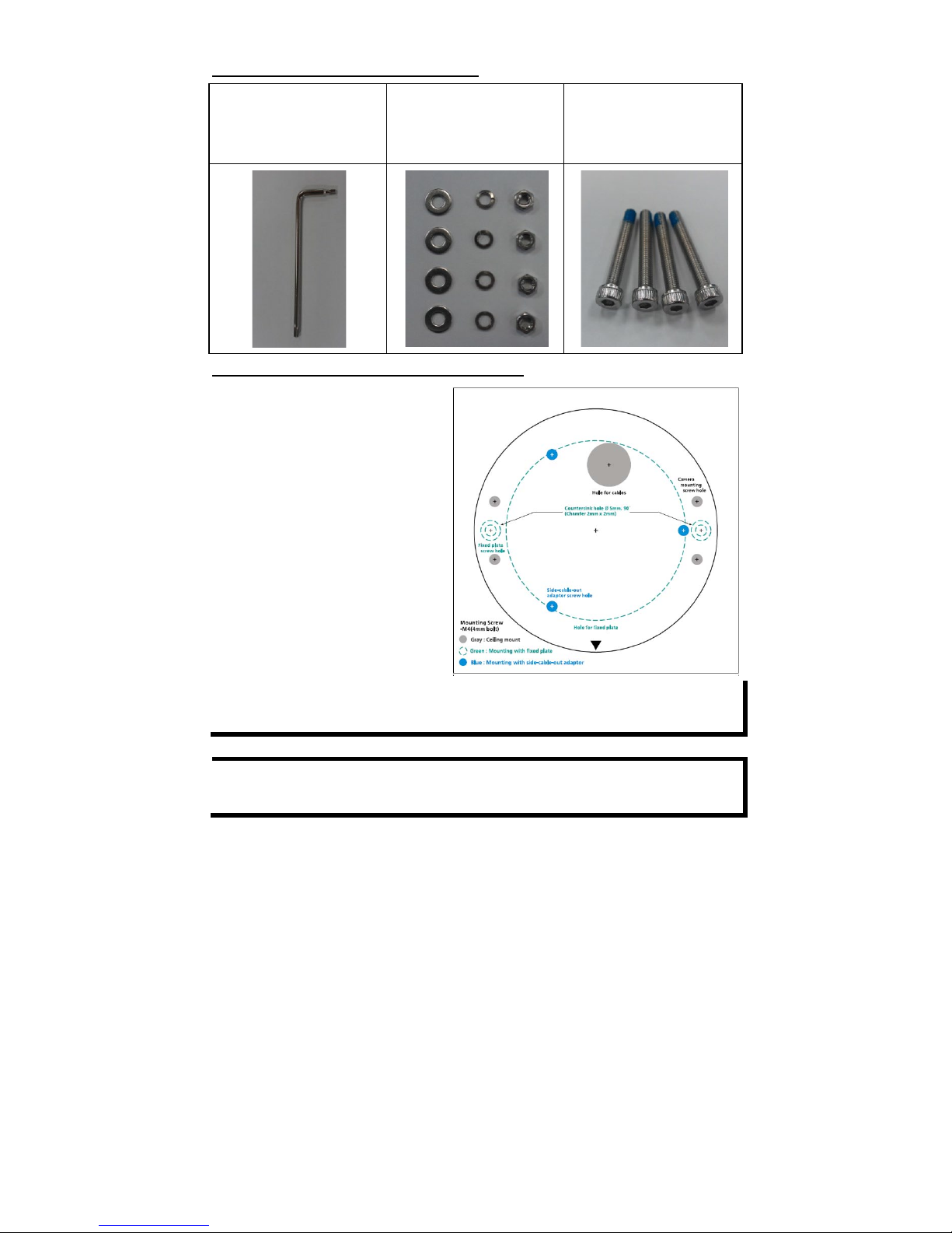
Screw handle accessory package
Torx screw driver for
attaching/detaching
the upper case.
4 sets of nut, gasket,
and spring washer for
mounting the camera.
4 indented hexagonal
head tapping screws for
mounting the camera
on the ceiling.
Sticker for camera mounting positions
Quick Installation Guide
Documentation and
Software
CD (includes User’s Manual,
Quick Installation Guide, and
VPort Utility)
Warranty card
NOTE
Check the model name on the VPort’s s ide la bel to determine if
the model name is correct for your order.
NOTE
This product must be installed in compliance with your loca l laws
and regulations.
Features
• 1/2.7” HD progressive CMOS image sensor
• High image quality with WDR ( wide dynamic ran ge) and DNR (D igital
Noise Reduction) supported
• Minimum illumination up to 0.2 lux (color)
• Supports MJPEG and H.264 Dual Codecs
• Provides 3 video streams for H.264 and MJPEG simultaneously
• Video stream up to 30 frames/sec at WXGA (1280 x 800) resolution
• Supports video quality configuration with fixed bit rate (CBR) and
fixed quality (VBR)
• Video latency under 200 ms
• DynaStream™ for network efficiency with dynamic frame rate change
• CBR Pro™ supported for high image quality with limited bandw idth
transmissions
• WXGA, 720P, SVGA, Full D1, 4CIF, VGA, CIF, QCIF resolution
• TCP, UDP, and HTTP network transmission modes
Page 4
- 4 -
• Supports DHCP OPT66/67 for automatic configuration from TFTP
server, making it easy to batch configure several units
• Supports RTSP streaming
• Supports multicast (IGMP) video streaming
• Supports SNMP (V1/V2C/V3) for network system integration and
management
• Supports QoS (ToS) for transmission priority
• Built-in web server for easy configuration
• Accessible IP filtering
• UPnP supported
• Compliant with EN 50121-3-2 and relevant sections of EN 50155
(compliant with IEC 60571)
• 1 10/100BaseT(X) port with M12 D-code connector
• 1 audio input with water-proof RCA-type connector
• IP66 rain and dust protection, with dehumidifying membrane
• PoE (Power-over-Ethernet, IEEE 802.3af) supported
• EN 62262 IK9 level vandal resistance
• -25 to 55°C (EN 50155, Class T1), or -40 to 70°C (EN 50155. Class TX)
operating temperature for rolling stock enviro n ments
• CE, FCC, UL 60950-1
• Built-in tamper alarm and Video Motion Detection (VMD)
• Pre, Trigger, and post snapshot images supported
• Sequential snapshot images supported
• Supports SMTP and FTP for alarm message transmission
• Supports HTTP event server
• 5-year warranty
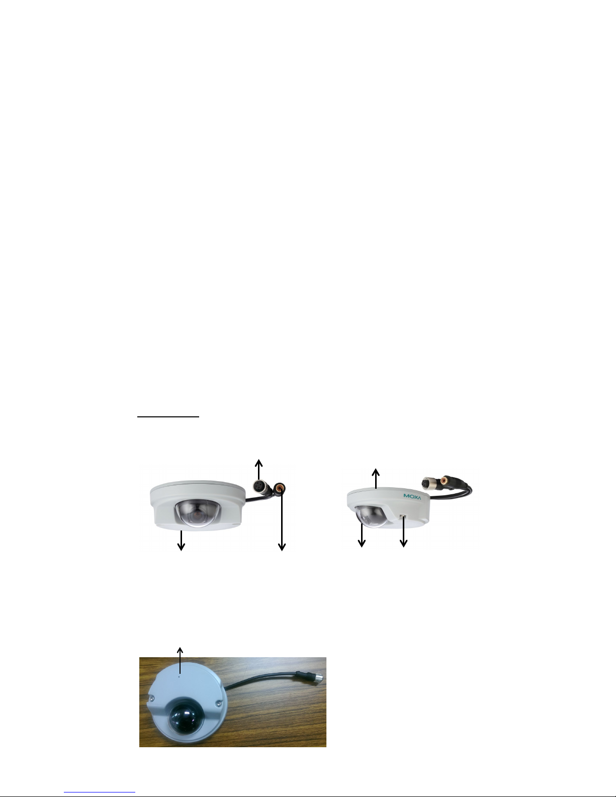
Product Description
Appearance
Transparent
Dome cover
4-pin D-code M12
Ethernet connector
RCA female
Connector
(only available in
models with linein audio)
Solid plastic
top cover
Aluminum
bottom plate
Torx screw
for top cover
Built-in Microphone (-MIC model)
Page 5
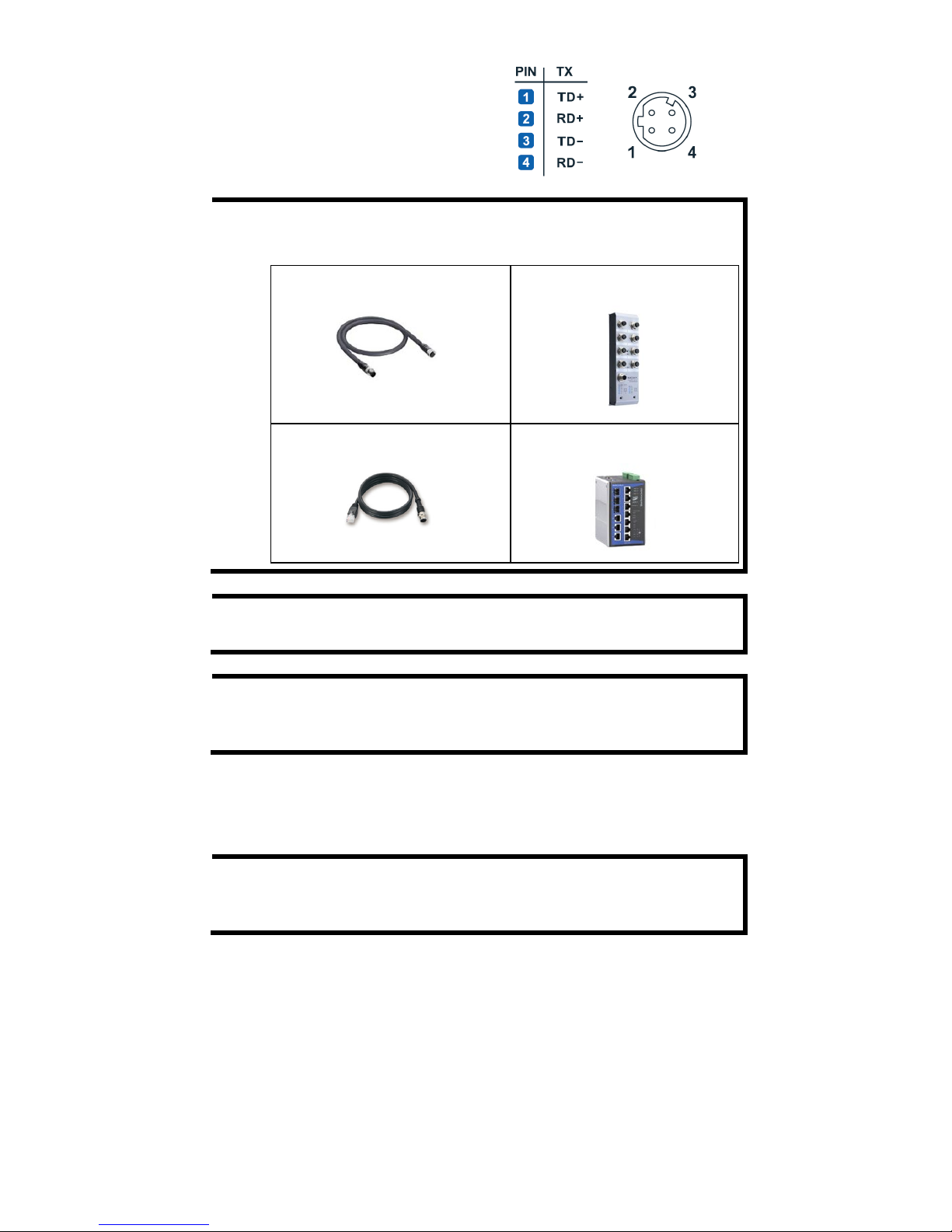
- 5 -
•
4-pin D-code M12 Ethernet
connector: Can be used for both
the PoE power supply
(Mode A) and
Auto MDI/MDI-X Ethernet
connection
NOTE
To connect the VPort P06-1MP-M12 to a network, use an
Ethernet cable with D
-code M12 connector and an M12 PoE
switch or RJ45 PoE switch
M12 D-code to M12 D-code
cable
M12 PoE switch (e.g.,
TN-5508-4PoE)
M12 D-code and RJ45 cable
RJ45 PoE switch
(e.g., EDS-P510)
NOTE
The power input rating of the VPort P06-1MP-M12 is 48 VDC,
0.12 A, with maximum power consumption approximately 6 W.
NOTE
The equipment is designed for in build ing instal lation on ly and is
not intended to be connected to exposed (outside the plant)
networks
• RCA female connector: The VPort P06-1MP-M12 supports one
audio input with RCA female connector. The audio will be digitized
and compressed as an audio stream for network transmission with
the video stream.
NOTE
RCA audio connectors are popular and easily found in the mark et.
If you require any other kind of audio connector, please contact
your Moxa sales representative for custom izatio n service.
• Solid plastic top cover: This top cover can be removed for tuning
the camera lens position.
• Transparent dome cover: The V Port P06-1MP-M12 is designed with
a transparent PC dome cover, which is vanda l-proof and satisfies EN
62262 (IEC 62262) Class IK9 requirements.
• 2 Torx screws for top cover: These 2 torx scr ews are designed wit h
anti-shedding to make installation more convenient. Use the L-type
torx screwdriver to remove or attach the top cover.
• Built-in microphone: VPort P06-1MP-M12-MIC series products
have a built-in microphon e, and can simultaneously disp lay or record
live video and audio.
Page 6

- 6 -
NOTE
The color of the form factor can be customized based on your
installation environment. Please contact your Moxa sales
representative for customization service.
Inside the Camera
• Mounting screw holes: There are 4 mounting screw holes for
mounting the VPort P06-1MP-M12 on the ceiling or the accessory.
• Thumb screw for fixing the lens’s position: To tune the lens’s
position, loosen the thumb screw, and then retighten it after the
position tuning is done.
• Lens with fixed focal length: The VPort P06-1MP-M12 series
includes models with 3 different focal lengths. Choose the appropriate
focal-length lens based on the viewing angle and object distance.
• Hardware reset button: Use a pointed object to depress the reset
button to reboot or restore factory defaults.
Reboot: press the button one time.
Factory default: press the button and hold in for at least 90 sec.
• Calibration for rotating lens (0 to 360°): Rotate the lens to get
the optimal image. When done, mark the position of this calibration
for future placement or mass installation.
Microphone line (-MIC model)
Page 7

- 7 -
• Calibration for tuning lens’s vertical position (0 to 90°): After
tuning the lens’s vertical position, mark the position of this calibration
for future placement or mass installation.
• Calibration for tuning lens’s horizontal position (±30°): After
tuning the lens’s horizontal position, mark the position of this
calibration for future placement or mass installation.
Hardware Installation
Step 1: Open and remove the top cover.
Use the torx screwdriver to loosen the top cover screws.
Step 2: Use the installation sticker for drilling the holes. There are
3 types of installation.
a.
Mounting with 4 mounting screws
To mount the camera on the ceiling, drill a hole through the gray
portion of the sticker and then mount the camera with the 4
nut/gasket/spring
-washer sets and 4 indented hexagonal head
tapping screws.
b.
Mounting with the side-cable-out adapter
Use the side
-cable-out
adapter
(VP
-SCO1) if your installation
requires the cable
–out on the
side. Drill a hole through the
blue portion of the sticker for
mounting the adaptor on the
surface with 3 nut/gasket/
spring
-washer sets and
indented hexagonal head
tapping screws. Then,
mount
the VPort P06
-1MP-
M12 on the
adapter with 4 M4 screws,
which are provided in the
VP-SCO1’s package.
VP-SCO1
Page 8

- 8 -
c.
Mounting with the fixed plate
If you cannot use the
nut/gasket/spring
-washer set
to mount the camera on your
ceiling, use
the VP-FP1 fixed
plate. Drill holes through the
green dotted
-line holes and 4
camera mounting screw holes
on the sticker, and then put the
VP-FP1 inside the hole. Use the
2 countersink screws to mount
the VP-SP1. Finally, mount the
VPort P06
-1MP-M12 on the
fixed plate with the 4 indented
hexagonal head tapping
screws.
VP-FP1
Page 9

- 9 -
NOTE
The screw hole for mounting the VP-FP1 fixed plate is a
countersunk hole with 5 mm diameter, and 90° 2 x 2 mm
chamfer. Take this into consideration when drilling these 2 screw
holes.
Step 3: Connect the camera with
the 4
-pin M12 D-code Ethernet
connector and RCA male
connector.
Step 4: Loosen the thumb screw
for tuning the horizontal, vertical,
and rotating lens position. Once the
lens position is correct,
fix the
thumb screw.
Step 5: Fix the top cover. The installation is now complete.
Software Installation
Step 1: Configure the VPort P06-1MP-M12’s IP address
When the VPort P06-1MP-M12 is first powered on, the POST (Power On
Self Test) will run for a few moments (about 30 seconds). The n etwork
environment determines how the IP address is assigned.
Network Environment with DHCP Server
For this network environment, the unit’s IP address will be assigned by
the network’s DH CP server. Refer t o the DHCP server’s IP address table to
determine the unit’s assigned IP address. You may also use the Moxa
VPort and EtherDevice Configurator Utility (edscfgui.exe), as described
below:
Using the Moxa VPort and EtherDevice Configurator Utility
(edscfgui.exe)
1. Run the edscfgui.exe program to search for the VPort. After the
utility’s window opens, you may also click on the Search button
to initiate a search.
2. When the search has concluded , the Model Name, MAC address, IP
address, serial port, and HTTP port of the VPort will be listed in the
utility’s window.
Page 10

- 10 -
You can double click the selected VPort, or use the IE web browser to
access the VPort’s web-based manager (web server).
Non DHCP Server Network Environment
If your VPort 16-M12 is connected to a network that does not have a
DHCP server, then you will need to configure the IP address manually.
The default IP address of the VPort 16-M12 is 192.168.127.100 and the
default subnet mask is 255.255.255.0. Note that you may need to c hange
your computer’s IP address and subnet mask so that the computer is on
the same subnet as the VPort.
To change the IP address of the VPort manually, access the VPort’s web
server, and then navigate to the System Configuration Network
General page to configure the IP address and other network settings.
Check Use fixed IP address to ensure that the IP address you assign is not
deleted each time the VPort is restarted.
Step 2: Access the VPort P06-1MP-M12’s web-based manager.
Type the IP address in the web browser’s address input box and then
press enter.
Step 3: Install the ActiveX Control Plug-in.
A security warning message will appear the first time you access the
VPort’s web-based manager. The message is related to installing the
VPort AcitveX Control component on your PC or notebook. Click Yes to
install this plug-in to enable the IE web browser for viewing video images.
NOTE
For Windows XP SP2 or above operating systems, the ActiveX
Control component will be blocked for system security reasons.
In this case, the VPort’s security warning message window may
not appear. You should unlock the ActiveX control blocked
function or disable the security configurat ion to enable the
installation of the VPort’s ActiveX Control component.
Page 11

- 11 -
Step 4: Access the homepage of VPort P06-1MP-M12's web-based
manager.
After installing the ActiveX Control component , the homepage of the
VPort P06-1MP-M12’s web-based manager will appear. Check the
following items to make sure the system was installed properly:
1. Video Images
2. Video Information
Step 5: Access the VPort’s system configurat ion .
Click on System Configuration to access the overview of the system
configuration to change the configuration. Model N ame, Server Name,
IP Address, MAC Address, and Firmware Version appear on the
green bar near the top of the page. Use this information to check the
system information and installation.
For details of each configuration, check the user’s manual on the software
CD.
Page 12

- 12 -
Wiring Requirements
ATTENTION
Safety First!
Be sure to disconnect the power cord before installing and/or
wiring your Moxa VPort P06
-1MP-M12. Calculate th e maximum
possible current in each power wire and common wire. Observe
all electrical codes dictating the maximum current
allowable for
each wire size. If the current goes above the maximum ratings,
the wiring could overheat, causing serious damage to your
equipment.
You should also pay attention to the following:
• Use separate paths to route wiring for power and devices. If power
wiring and device wiring paths must cross, make sure the wires are
perpendicular at the intersection point.
• You can use the type of signal transmitted thro u gh a wire to
determine which wires should be k ept separat e. The ru le of thumb is
that wiring that shares similar electrical characteristics can be
bundled together.
• Keep input wiring and output wiring separate.
• We strongly advise labeling wiring to all devices in the system.
Dimensions (mm)
Front View
Bottom View
Top View
Camera with SCO1 adaptor
Page 13

- 13 -
Specifications
Camera
Sensor
1/2.7” HD progressive scan CMOS
Lens
3.6, 4.2, 6 mm fixed focal length
Angle of view 3.6 mm, F1.6: Diagonal 120°, Horizontal 96°,
Vertical 56°
4.2 mm, F1.6: Diagonal 96°, Horizontal 81°,
Vertical 47°
6.0 mm, F1.8: Diagonal 66°, Horizontal 51°,
Vertical 38°
Camera lens angle
Pan: ±30°; Tilt: 0-90°, Rotate: ±180°
(contolled manually)
Illumination
(Low light sensitivity)
0.2 Lux at F=1.2, color
Synchronization
Internal
White Balance
ATW/AWB (range: 3200 to 10000°K)
Electronic Shutter
Auto, 1/30 to 1/25000 sec.
S/N Ratio
50 dB (Gamma, Aperture, AGC, OFF; DNR ON)
DNR
Built-in DNR
WDR
Level 1 to 8
AGC Control
2X, 4X, 8X, 16X, 32X, 64X
Flickerless Control
50Hz/60Hz mode
Black level control
High/Medium/Low
Auto Exposure
Level ±5
Image Rotation
Flip, Mirror, and 180° rotation
Image Setting
Manual tuning with saturation, sharpness, an d
contrast
Video
Video Compression
H.264 (ISO/IEC 14496-10) or MJPEG
Video Output
Via Ethernet port
Video Streams
3 video streams (2 H.264 and 1 MJPEG)
Video Resolution and FPS (Frame per second):
NTSC
PAL
Size
Max. FPS
Size
Max. FPS
QCIF
176 x 112
30
176 x 144
25
CIF
352 x 240
30
352 x 288
25
VGA
640 x 480
30
640 x 480
25
4CIF
704 x 480
30
704 x 576
25
Full D1
720 x 480
30
720 x 576
25
SVGA
800 x 600
30
800 x 600
25
HD
1280x720
30
1280x720
25
WXGA
1280x800
30
1280x800
25
Page 14

- 14 -
Video Viewing • DynaStream™ supported for automatic
frame rate adjustment
• CBR Pro™ for good image quality in
limited
bandwidth transmission
• 3 configurable privacy mask areas
• Adjustable image size and quality
• Timestamp and text overlay
• OSD (On screen Display) position
adjustable
• Maximum of 5 simultaneous unicast
connections
Audio
Audio inputs
1 Line-in, rugged RCA connector, or
1 built-in microphone input
Audio format
Mono, PCM (G.711)
Network
Protocols
TCP, UDP, HTTP, SMT P, FTP, Telne t, NTP, DNS,
DHCP, UPnP, RTP, RTSP, ICMP, QoS,
SNMPv1/v2c/v3, DDNS, TFTP, OPT 66/67
Ethernet
1 10/100BaseT(X) Ethernet port, M12 D-code
connector
Power Requirements
Input
Power-over-Ethernet (IEEE 802.3af)
Consumption
Maximum 6 W
Physical Characteristics
Housing
IP66 rain and dust protection, vandal-proof
protection
Dehumidifying
Membrane
GORE protective vent
Dimensions
110 mm (diameter) x 47 mm (height)
Weight
310 g
Installation
Surface (ceiling) mounting
Environmental Limits
Operating Temperature
Standard models: -25 to 55°C (-13 to 131°F)
Wide temp. models: -40 to 70°C (-40 to 158°F)
Storage Temperature
-40 to 85°C (-40 to 185°F)
Ambient Relative
Humidity
5 to 95% (non-condensing)
Regulatory Approvals
Safety
UL60950-1
EMI
FCC Part 15 Subpart B Class A, EN 55022 Class A
EMS
EN61000-4-2 (ESD), Level 3
EN61000-4-3 (RS), Level 3
EN61000-4-4 (EFT), Level 3
EN61000-4-5 (Surge), Level 3
EN61000-4-6 (CS), Level 3
EN61000-4-8
Page 15

- 15 -
Rolling Stock EN 50155:2007 compliance (shock, vibration,
temperature, EMC)
Shock
IEC61373
Freefall
IEC60068-2-32
Vibration
IEC61373
Vandal resistance
IEC62262, Class IK9
MTBF (Mean-time
between failure)
1,944,678 hrs (Ground Benign);
206,189 hrs (Ground Mobile)
Warranty
5 years
Alarm Features
• Intelligent Video: Camera tamper
• Video Motion Detection: 3 independently configurable motion areas
• Scheduling: Daily repeat timing schedule
• Imaging: JPEG snapshots for pre/trigger/post alarm images
•
Email/FTP Messaging: Automatic transfer of stored images via email
or FTP as event-triggered actions
• Custom Alarms: HTTP event servers for setting customized alarm
• actions
Security
• Password: User level password protection
• Filtering: By IP address
• Encryption: HTTPS, SSH
Minimum Viewing System Requirements
• Pentium 4, 2.4 GHz
• 512 MB of memory
• Windows XP with SP3 and above, Windows 7
• Internet Explorer 9.x or above
• DirectX 9.0c or above
Software Development Kit
VPort SDK PLUS
Includes CGI commands, ActiveX Control, and
API library for customized applications or
system integration for third-party developer
Standard
ONVIF
Technical Support Contact Information
www.moxa.com/support
Moxa Americas:
Toll
-free: 1-888-669-2872
Tel:
+1-714-528-6777
Fax: +1-714-528-6778
Moxa China (Shanghai office):
Toll
-free: 800-820-5036
Tel:
+86-21-5258-9955
Fax: +86-21-5258-5505
Moxa Europe
:
Tel:
+49-89-3 70 03 99-0
Fax: +49-89-3 70 03 99-99
Moxa Asia
-Pacific:
Tel:
+886-2-8919-1230
Fax: +886-2-8919-1231
 Loading...