

Page 1

2012 Moxa Inc. All rights reserved.
P/N: 1802000260010
Moxa IP Camera
VPort 26 Series
Quick Installation Guide
First Edition, March 2012
Page 2
- 2 -
Overview
The VPort 26 series is a vandal-proof, IP66-rated, fixed dome IP camera
desinged for outdoor use. With SVGA (max. 800 x 600 ) resolution,
H.264/MJPEG 3 simutaneous video streams, and day-and-night camera
lens, the VPort 26 series is well-suited for outdoor video surveillance
applications.
To enhance video image quality, the VPort 26 series is equipped with a
2.8 to 11 mm vari-focal lens that meets any viewing angle and distance
requirements. With the built-in removeable IR-cut filter, and automatic
switching from color to B/W images, the VPort 26 series is suitable for
day-and-night use. Along with 3D-DNR (3D Digital Noise Reduction)
function, which can greatly reduce noises of video frames, and WDR
(Wide Dynamic Range), the VPort 26 series provides clear images under
back light circumstances. The optional De-mist function also ensures a
good image quality in rainy, snowy, or hazy environments.
The VPort 26 series is specially designed for outdoor applications with the
following features: IP66 rain and dust protection, high EMI/surge
protection, -40 to 50°C operating temperature without a fan or heater
required, metal housing, and vandal-proof dome cover. In addition, the
camera is built in a dehumidified membrane for spreading out the
moisture inside the camera. Users can choose either the model with PoE
(Power over Ethernet, 802.3af) function, or the wired power input model
with 12/24 VDC or 24 VAC.
The VPort 26 series is designed to provide both H.264 and MJPEG video
streams and transmit up to 3 independent video streams (2 in H.264, and
1 in MJPEG) simultaneously. The camera is able to encode and transmit
up to 30 FPS for each of the H.264 and MJPEG streams. Advanced
network security functions, such as 802.1x and SSH, are also provided to
prevent unauthorized access or data snooping, which is critical for most
surveillance applications
Package Checklist
Moxa’s VPort 26 is shipped with the following items. If any of these items
is missing or damaged, please contact your customer service
representative for assistance.
• 1 × VPort 26 (includes 2-pin terminal block for power input)
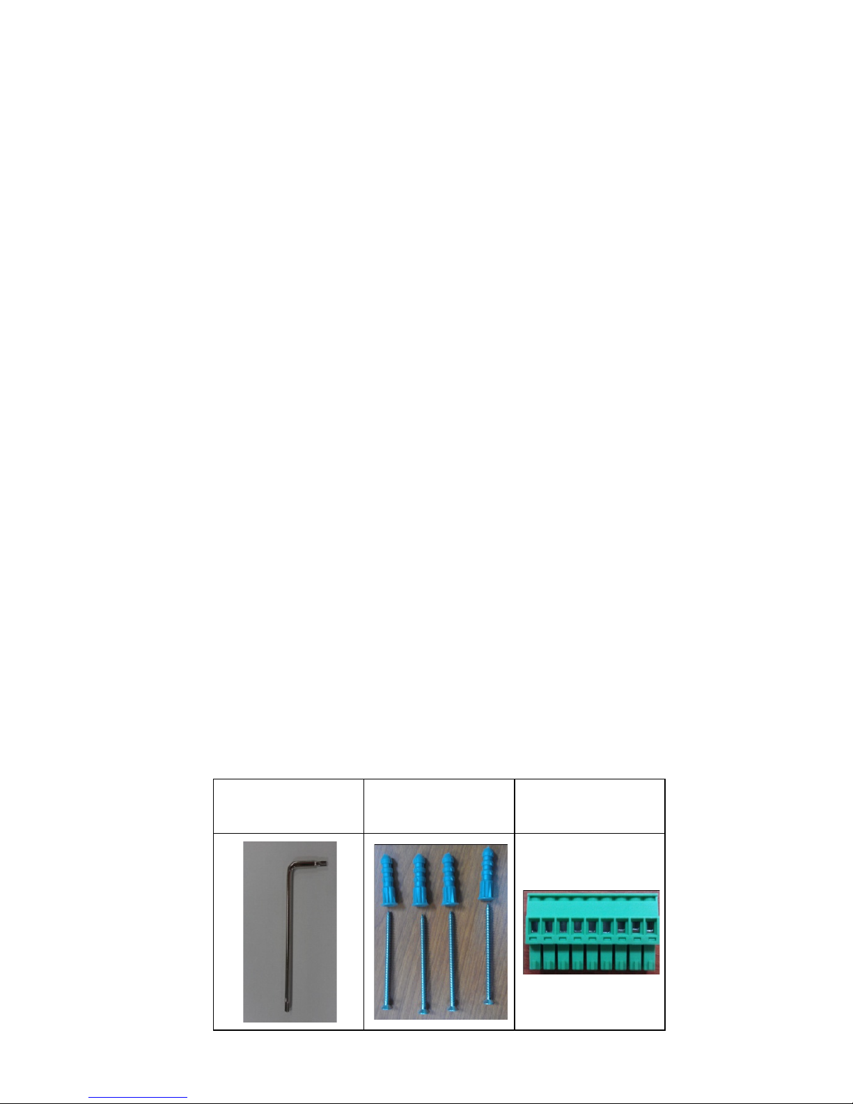
• Screw handle accessory package
Torx screw driver for
attaching/detaching
the upper case
4 sets of taping screws
(6 cm length) and
anchors
9-pin terminal block
for DI/Relay/ Audio
Page 3

- 3 -
• Cable glands accessories package
IP66 cable glands to
ensure IP66
protection when the
cables are connected
• Sticker for camera mounting positions
• Quick Installation Guide
• Document & Software CD (includes User’s Manual, Quick Installation
Guide, and VPort Utility)
• Warranty Statement
NOTE
Check the model name on the VPort’s side label to determine if
the model name is correct for your order.
NOTE
This product must be installed in compliance with your local laws
and regulations.
Features
High Video Image Quality
• 1/3” progressive CMOS sensor for SVGA (800x600) resolution
• Day and night viewing capability with ICR (IR cut filter) and
color/black & white image switch
• Supports 3D_DNR (3D digital noise reduction), BLC (Backlight
compensation) and WDR (wide dynamic range) for better image
quality
• Built-in de-mist function for sharp images in rain, fog, and hazy
environments
• Equipped with 2.8 mm to 11 mm vari-focal lens for wide-range fields
of view
• Minimum illumination up to 0.01 lux at F=1.2 (AGC 30db and
sense-up off)
• Image mirror and inverse
• 350° pan, 85° tilt and 360° rotate camera head angles for different
installation positions.
• Support up to 8 privacy mask areas and 4X digital zoom
Page 4

- 4 -
Excellent Video/Audio streaming and network transmission
performance
• Maximum 3 simultaneous video streams for H.264 and MJPEG codecs
• Video stream up to 30 frames/sec at SVGA (800 x 600) resolution (in
single stream)
• DynaStream™ supported for optimal network efficiency
• Video latency under 200 ms
• 1 audio input and 1 audio output supported for video/audio complete
surveillance solution
• SVGA/Full D1/ 4CIF/ VGA/ CIF/ QCIF resolution
• TCP, UDP and HTTP network transmission mode
• Supports RTSP Streaming
• Supports IGMP (ver.3) protocols for efficient network transmission
• Supports SNMP (V1/V2C/V3) for network system integration and
management
• Supports QoS (ToS) for transmission priority
• Adjustable frame rate and bit rate control
• User-friendly IP filtering
• Supports IEEE802.1X for network access authentications
• Supports HTTPS and SSH for network transmission security
• UPnP Supported
• Maximum 8 unicast video streams, and 50 multicast clients
• Support multicast push for all multicast clients
• OnVIF standard support for compatibility with other IP video products
• Modbus/TCP supported for direct communication with SCADA system
Rugged Design for Mission-critical Industrial Environments
• IP 66 form factor protection for rain and dust
• Model available with PoE (802.3af) or 12/24 VDC and 24 VAC power
input, with LED indicators
• Panel mounting for ceiling, or outdoor installation kit for versatile
installation method
• -40 to 50°C operating temperature for critical industrial environment
• No heater and fan for long MTBF
• CE, FCC, UL60950-1
• 3-year product warranty
Intelligent Alarm Triggered Capability
• Built-in Video Motion Detection (VMD)
• 1 DI and 1 Relay output (DO) for sensors and alarms
• Video loss and power failure alarm
• Pre, Trigger and post snapshot images supported
• Sequential pre-event snapshot images
• Sequential snapshot images supported
• Support SDHC slot for local storage with SD card in event recording
• Support SMTP and FTP for alarm message transmission
• Support HTTP Event Server
Video management and control
• Support for Moxa SoftNVR-IA IP surveillance software, a video
recording and management solution
• Free MOXA VPort SDK Plus with CGI Commands, ActiveX Control and
API support for third-party developers
Page 5
- 5 -
NOTE
The VPort P26 has PoE (802.3 af) power input, and the VPort 26
has 12/24 VDC or 24VAC power input.
NOTE
If you are interested in the Moxa VPort SDK PLUS, please go to
Moxa’s
website (www.moxa.com) to download the software, or
contact a Moxa sales representative for more information.
NOTE
If you are interested in SoftNVR
-IA IP surveillance software,
please go to Moxa’s website (www.moxa.com) to download the
trial version.
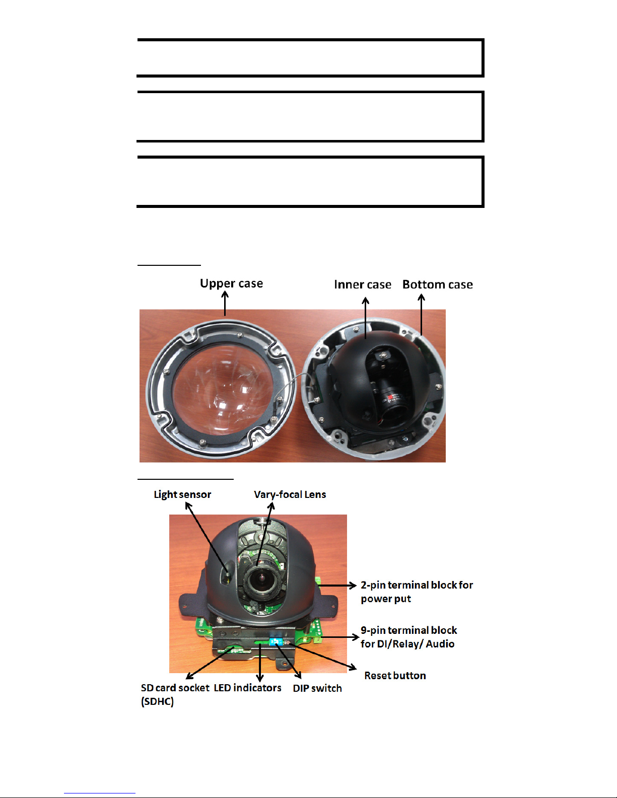
Product Description of the VPort 26
Form Factor
IP Camera Module
Page 6
- 6 -
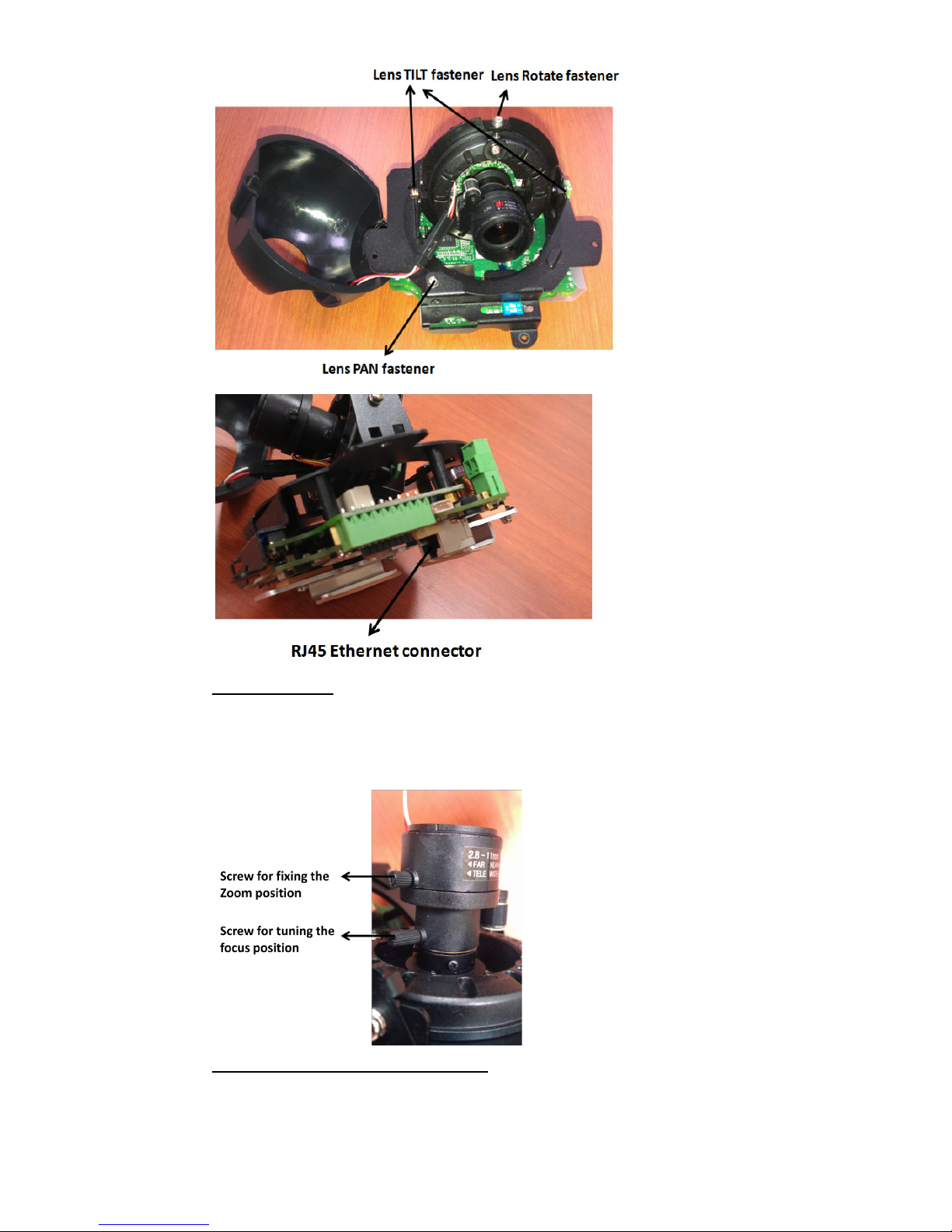
Vari-focal Lens
The VPort 26 series comes with a day and night 2.8 to 11 mm vari-focal
lens for providing high quality video images. Users can adjust the Zoom
and Focus manually to get clear images regardless of the site
environment.
Pan, Rotation and Tilt Adjustment
Use the pan, rotation and tilt fasteners for panning, rotating and tilting
the lens angles. To do this, the screws must be loosened in advance. After
the lens angles are correct, tighten the screws to fix the angles.
Page 7
- 7 -
Light Sensor
The VPort 26 includes a light sensor for detecting illumination, which is for
enabling the ICR (IR-cut filter removable) function. When the illumination
is under 3 lux, the image will be switched to night mode in black and white,
and when the illumination is greater than 5 lux, the image will be switched
back to day mode in color.
2-pin Terminal Blocks for Power Input
VPort 26 series has comes in two models: the VPort 26
is powered with 12/24VDC or 24VAC, and
the VPort
P26 is power with PoE (Power over Ethernet, 802.3af).
This 2 pin terminal block is for the direct-wired power
input
of the VPort 26.
NOTE
The specifications of the direct-wire power input are 12-32 VDC
for 12/24 VDC power input, or 18-30 VAC for 24 VAC power input.
The maximum power consumption is 11.7 Watt.
9-pin Terminal Block Connector for DI, DO, and Audio
The VPort 26 supports 1 DI (digital input), 1 DO (relay output), 1 audio
input (line-in or mic-in), and 1 audio output (line-out) through the 9-pin
terminal block.
DO
(Relay Output)
NO (Normal Open)
Max. 1A, 24 VDC
Initial status is Normal Open
C (Common)
NC (Normal Close)
DI (Digital Input)
+
High: +13V to +30V
Low: -30V to +3V
-
Page 8

- 8 -
LED Indicators and DIP Switche
The VPort 26 has 3 LEDs for indicating the power
status, 10/100 Mbps Ethernet link, and system
status. In addition, one DIP switch (No.2) is
provided for enabling or disabling the LED light
for users who do not want the LED l
ight to be
visible at night.
LED
Description
Power
On: power on
Off: power off
10/100 M Amber: Ethernet link is 10 Mbps
Green: Ethernet link is 100 Mbps
System
Red On
Hardware initialization
Red blinking
Software initialization
Green On
System boot-up successfully
Green blinking
Firmware upgrade proceeding
DIP Switch 1
Reserved
DIP Switch 2
On: LED light is on
Off: LED light is off
SD card Socket (SDHC)
The VPort 26 supports a standard SDHC interface for local storage with a
current maximum size of 32 GB. The user can use an SD card which is fits
this specification. Currently, the local storage supports triggered video
recording when an event has occurred.
NOTE
You are recommended to use Transcend or Sandisk SD cards.
Sandisk Extreme III SD cards are highly recommended due their
read/write speed.
NOTE
To check if the SD card is mounted successfully, please go to
system configuration
Local storage in the VPort’s web-based
manager
Reset Button
The reset button is used to reset the camera hardware.
1. Reboot:
To reboot the VPort 26, power it off and then power it back on again, or
push the RESET button one time. The System LED will light in red as the
POST (Power on Self Test) process runs. When the rebooting process is
finished, the System LED will change to a green color.
2. Restore to Factory Settings:
To restore the VPort 26 to the factory default settings, press the reset
button continuously until the System LED blinks in red. After the system
LED stops blinking, release the reset button. The POST process will run,
and the VPort will reboot. The System LED will light in green when the
VPort has finished rebooting.
Page 9

- 9 -
RJ45 Ethernet Port
The RJ45 Ethernet port is for 10/100Mbps network transmission, in
addition to PoE (power over Ethernet, 802.3af) power supply for VPort
P26.
NOTE
The VPort P26 supports standard IEEE 802.3af
Po
wer-over-
Ethernet (PoE). The power input rating is 48V/0.11A,
and the maximum power consumption is about 4.8W.
NOTE
The equipment is designed for in building installation only and is
not intended to be connected to exposed (outside plant)
networks.
First-Time Installation and Configuration
Before installing the VPort 26, check to make sure that all items in the
Package Checklist are in the box. In addition, you will need access to a
notebook computer or PC equipped with an Ethernet port.
Hardware Installation
Step 1:
Open and remove the upper case.
Use the Security Torx to loosen the upper case screws.
Step 2:
Remove the inner case.
Loosen 4 screws, and take out the IP camera module.
Page 10

- 10 -
Step 3:
Connect the cables.
a)
Open the conduit hole. (use the side conduit hole as
example)
b)
Prepare the cable gland (if required).
C)
Use the cable gland to assemble the cables.
Page 11

- 11 -
NOTE
When installing the cable gland, make sure the 2 rubber rings are
assembled properly for IP66 protection. If necessary, use silicon
sealant.
d)
Connect the cables to the IP camera module’s
connectors.
Remove the protective plastic film in the bottom of IP camera
module. Then connect the Ethernet cable to RJ45 Ethernet
port, as well as the terminal blocks wi
th power line and DI
/DO/ Audio lines (if
used).
Page 12

- 12 -
NOTE
Be sure to arrange the cables carefully to make sure that all
cables are connected properly. We recommend connecting the
Ethernet cable first, and then the 9
-pin terminal block. Connect
the 2-pin terminal block last.
NOTE
The conduit hole must face downward to provide the VPort 26
with IP66 protection against rain when installed in an outdoor
environment.
Step 4:
Mount the bottom case on the ceiling or accessory’s
mounting kit (VP
-MK2)
a)
Mounting on the ceiling
Step 1:
Use the installation stick or attach the bottom case to
the appropriate mounting location on the wall, and
mark the positions of the four screw holes with a pen
or a pencil.
Page 13

- 13 -
Step 2:
In the marked locations, drill a hole slightly smaller
than the supplied screw
anchors.
Step3:
Put anchors into these drilled holes.
Step 4:
Fasten the
bottom case with the four copper pillar
s
crews.
b)
Mounting on the accessory’s mounting kit (VP-MK2)
Step 1:
Fasten the bottom case on the plate with the four
machine screws, which are provided in VP
-MK2’s
accessory package.
Step 2:
Assemble the mounting kit with the selected
accessory.
VPort 26 + VP-MK2
+ VP-520L
VPort 26 + VP-MK2
+ VP-520HB
NOTE
Choose
the appropriate mounting accessories based on the
installation requirements.
Page 14

- 14 -
Step 5:
Assemble the IP Camera Module with the bottom case.
Step 6:
To get the desired video image, adjust the angles and
zoom strength.
a)
Pan adjustment
Page 15

- 15 -
b)
Tilt adjustment
c)
Rotate adjustment
Page 16

- 16 -
d)
Zoom adjustment
Step 8:
Fasten the upper case with bottom case to complete the
hardware installation.
Software Installation
Step 1: Configure the VPort 26’s IP address
When the VPort 26 is first powered on, the POST (Power On Self Test) will
run for a few moments. The System LED will turn green when the POST is
complete. The 10 Mbps or 100 Mbps LED will then flash as the IP address
is assigned. The network environment determines how the IP address is
assigned.
Network Environment with DHCP Server
For this network environment, the unit’s IP address will be assigned by
the network’s DHCP server. Refer to the DHCP server’s IP address table to
determine the unit’s assigned IP address. You may also use the Moxa
VPort and Ether Device Configurator Utility (edscfgui.exe), as described
below:
Using the Moxa VPort and EtherDevice Configurator Utility
(edscfgui.exe)
1. Run the edscfgui.exe program to search for the VPort. After the
utility’s window opens, you may also click on the Search button
to initiate a search.
2. When the search has concluded, the Model Name, MAC address, IP
address, serial port, and HTTP port of the VPort will be listed in the
utility’s window.
Page 17

- 17 -
NOTE
The Serial number is the production serial number of this VPort,
and the HTTP Port number is the http port used by this VPort.
3. Users can double click the selected VPort, or use the IE web browser
to access the VPort’s web-based manager (web server).
Non DHCP Server Network Environment
If your VPort 26 is connected to a network that does not have a DHCP
server, then you will need to configure the IP address manually. The
default IP address of the VPort 26 is 192.168.127.100 and the default
subnet mask is 255.255.255.0. Note that you may need to change your
computer’s IP address and subnet mask so that the computer is on the
same subnet as the VPort.
To change the IP address of the VPort manually, access the VPort’s web
server, and then navigate to the System Configuration Network
General page to configure the IP address and other network settings.
Check the Use fixed IP address to ensure that the IP address you
assign is not deleted each time the VPort is restarted.
Step 2: Accessing the VPort 26’s web-based manager
Type the IP address in the web browser’s address input box and then
press enter.
Step 3: Install the ActiveX Control Plug-in
A security warning message will appear the first time you access the
VPort’s web-based manager. The message is related to installing the
VPort AcitveX Control component on your PC or notebook. Click Yes to
install this plug-in to enable the IE web browser for viewing video images.
NOTE
For Windows XP SP2 or above operating systems, the ActiveX
Control component will be blocked for system security reasons.
In this case, the VPort’s security warning message window may
not appear. Users should unlock the ActiveX control blocked
function or
disable the security configuration to enable the
installation of the VPort’s ActiveX Control component.
Step 4: Access the homepage of VPort 26’s web-based manager.
After installing the ActiveX Control component, the homepage of the
VPort 26’s web-based manager will appear. Check the following items to
make sure the system was installed properly:
1. Video Images
2. Audio Sound (make sure your PC’s or notebook’s sound is turned on)
3. Video Information
Page 18

- 18 -
Step 5: Access VPort’s system configuration.
Click on System Configuration to access the overview of the system
configuration to change the configuration. Model Name, Server Name,
IP Address, MAC Address, Firmware Version, and LED Status
appear in the green bar near the top of the page. Use this information to
check the system information and installation.
For details of each configuration, check the User’s Manual on the software
CD.
Page 19

- 19 -
Wiring Requirements
ATTENTION
Safety First!
Be sure to disconnect the power cord before installing and/or
wiring your
Moxa VPort 26.
Calculate the maximum possible current in each power wire and
common wire. Observe all electrical codes dictating the
maximum current allowable for each wire size.
If the current goes above the maximum ratings, the wiring could
overheat, causing serious damage to your equipment.
You should also pay attention to the following:
• Use separate paths to route wiring for power and devices. If power
wiring and device wiring paths must cross, make sure the wires are
perpendicular at the intersection point.
• You can use the type of signal transmitted through a wire to
determine which wires should be kept separate. The rule of thumb is
that wiring that shares similar electrical characteristics can be
bundled together.
• Keep input wiring and output wiring separated.
• It is strongly advised that you label wiring to all devices in the system
when necessary.
Dimension
Page 20

- 20 -
Specifications
Camera
Sensor
1/3” SVGA progressive scan CMOS
Lens
Wide end: F=1.4, Diagonal 125.2°, horizontal
97.1
°, vertical 71.1°
Tele End:
F=2.8, diagonal 31.6°, horizontal
25.3°, vertical 19.0°
Focal length= 2.8 to 11 mm
Auto Iris type
DC drive
Camera Angle
Pan: ±175°; Tilt: 0 to 85°; Rotation: ±180°
Minimum illumination
(low light sensitivity)
0.01 lux, F=1.2
Synchronization
Internal
Gamma Correction
0.45
White Balance
ATW/AWB (range: 3200 to 10000°K)
ICR Control
Auto
S/N Ratio
52dB (TYP) (Gamma, Aperture, AGC Off;
3D-DNR On)
DNR
Built-in 3D-DNR (3D digital noise reduction)
WDR
94 dB, Level 1 to Level 9
De-mist
Off, low, medium, high
AGC Control
Level 1 to Level 9
Backlight Compensation
On/off with selectable areas
Digital Zoom
4X
Auto Light Control
Level 1 to Level 8
Image Rotation:
Flip, Mirror, and 180° rotation
Image Setting
Manual tuning with saturation and sharpness
Video
Video Compression
H.264 (ISO/IEC 14496-10) or MJPEG
Video Output
Via Ethernet port
Video Streams
Maximum of 3 video streams (2 x H.264, 1 x
MJPEG)
Video Resolution and FPS (Frame per second):
NTSC
PAL
Size
Max. FPS
Size
Max. FPS
QCIF
176 x 112
30
176 x 144
25
CIF
352 x 240
30
352 x 288
25
VGA
640 x 480
30
640 x 480
25
4CIF
704 x 480
30
704 x 576
25
Full D1
720 x 480
30
720 x 576
25
SVGA
800 x 600
30
800 x 600
25
Video Viewing
DynaStream™ supported for changing the
video frame rate automatically
8 privacy mask areas provided
Adjustable image size and quality
Timestamp and text overlay
PTZ
Digital PTZ with 4X zoom
Audio
Audio Input
1 Line-in or MIC-in with 2-pin terminal block
connector
Audio Output
1 Line out with 2-pin terminal block connector
Page 21

- 21 -
Network
Protocols
TCP, UDP, HTTP, SMTP, FTP, Telnet, NTP, DNS,
DHCP, UPnP, RTP, RTSP, ICMP, IGMPv3, QoS
,
SNMPv1/v2c/v3, DDNS, Modbus/TCP, 802.1X,
SSH, HTTPS
Ethernet
1 10/100BaseT(X) Ethernet port, RJ45
connector
GPIO
Digital Input
1, max. 8 mA
“
High”: +13V to +30V
“Low”: -30V to +3V
Relay Output
1 (max. 24 VDC @ 1A)
LED Indicators
Network
10 Mbps or 100 Mbps
Power
Power On/Off
System
Indicates if the system booted properly or not
DIP Switch
For turning the LED light ON or Off
Power
Input
VPort 26: 1, 12/24 VDC or 24 VAC with 2
-pin
terminal block connector
VPort
P26: 1, Power-over-Ethernet
(IEEE802.3af)
Consumption
Max. 11.7W
Physical Properties
Housing
Metal, IP66 rated for rain and dust protection,
vandal-resistant
Dimensions
Diameter: 149 mm (5.7 in)
Height: 1w0 mm ( 4.7 in)
Weight
1.4 kg
Installation
Surface mounting, or outdoor mounting with
accessories
Environmental Limits
Operating Temperature
-40 to 50°C (-40 to 122°F )
Storage Temperature
-40 to 85°C (-40 to 185°F)
Ambient Relative
Humidity
5 to 95% (non-condensing)
Regulatory Approvals
UL
UL 60950-1
EMI
FCC Part 15, CISPR (EN55022) class A
EMS
EN61000-4-2 (ESD), Level 3
EN61000
-4-3 (RS), Level 3
EN61000
-4-4 (EFT), Level 3
EN61000
-4-5 (Surge), Level 3
EN61000
-4-6 (CS), Level 3
EN61000
-4-8
EN61000-4-11
Shock
IEC60068-2-27
Freefall
IEC60068-2-32
Vibration
IEC60068-2-6
Vandal-resistant
EN 62262, IK10 level
Warranty
3 years
Page 22

- 22 -
Alarm Features
• Intelligent Video: Camera tamper (Pending)
•
Video motion detection with sensitivity tuning
•
Video loss alarm
•
Daily repeat timing schedule
•
JPEG snapshots for pre/trigger/post alarm images
•
Automatic transfer of stored images via email or FTP as
event-triggered actions
•
HTTP event servers and CGI events for setting customized alarm
actions
• 24 MB pre-alarm video buffer for JPEG snapshot images
Security
• User level password protection
IP address filtering
•
802.1X authentication
• HTTPS, SSH encryption
Minimum Viewing System Requirements
Pentium 4, 2.4 GHz
512
MB of memory
Windows XP/2000
with SP4 or above
Internet Explorer 6.x or above
DirectX 9.0c or above
Software Development Kit
VPort SDK PLUS
Includes CGI commands, ActiveX Control, and
API library for customized applications or
system integration for third
-party developers
(the latest version of SDK is vailable for
download from
Moxa’s website).
Standard
ONVIF
Technical Support Contact Information
www.moxa.com/support
Moxa Americas:
Toll
-free: 1-888-669-2872
Tel:
1-714-528-6777
Fax:
1-714-528-6778
Moxa China (Shanghai office):
Toll
-free: 800-820-5036
Tel:
+86-21-5258-9955
Fax:
+86-21-5258-5505
Moxa Europe
:
Tel:
+49-89-3 70 03 99-0
Fax:
+49-89-3 70 03 99-99
Moxa Asia
-Pacific:
Tel:
+886-2-8919-1230
Fax:
+886-2-8919-1231
 Loading...