

Page 1

2011 Moxa Inc. All rights reserved.
P/N: 1802000160010
Moxa IP Camera
VPort 16-M12 Series
Quick Installation Guide
First Edition, December 2011
Page 2
- 2 -
Overview
The VPort 16-M12 is a compact, fixed-IP camera with EN 50155:2007
compliance that is specially designed for rolling stock CCTV applications.
In addition to the -25 to 55°C operating temperature, IP66 rain and dust
protection, anti-vibration M12 Ethernet connector, Power-over-Ethernet
(PoE), and metal housing with glass lens cover, the VPort 16-M12 also
has a built-in dehumidifying membrane for dissipating moisture trapped
inside the camera and keeping other moisture out. This innovative design
greatly reduces the impact of moisture on the lens.
To provide good video quality, the VPort 16-M12 uses a 1/3" CCD image
sensor and advanced 3D-deinterlacing hardware enhancements, making
it suitable for most lighting conditions. A maximum of 2 H.264 and 1
MJPEG video streams are provided by the VPort 16-M12. In addition,
Moxa’s DynaStream™ function allows you to change the video frame rate
automatically, which can help you control your network bandwidth budget
and ease network system management. The VPort 16-M12 also has a
built-in SDHC slot for installing an SD card to provide up to 32 GB of local
storage.
The VPort 16-M12 supports both surface mounting and embedded
mounting, and for different viewing angles and distance requirements, 5
lens types with focal length from 3 mm to 16 mm are provided. Moreover,
the camera head can be calibrated according to the scale on the camera
and can be rotated 360° horizontally and 90° vertically, and DHCP opt
66/67 is also supported for automatic configuration, making mass
installation a much easier task.
Package Checklist
Moxa’s VPort 16-M12 is shipped with the following items. If any of these
items is missing or damaged, please contact your customer service
representative for assistance.
• 1 × VPort 16-M12 or VPort 16-M12-DO (Lens is included)
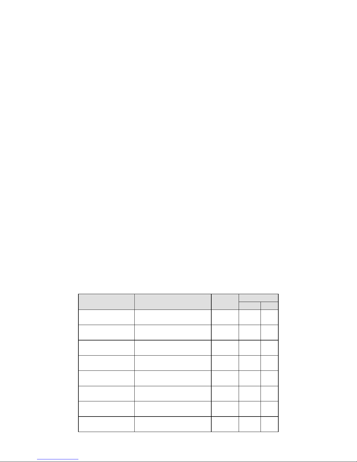
Standard model Dome cover model Lens
Modulation
NTSC
PAL
VPort 16-M12CAM3L5430N
VPort 16-DO-M12CAM3L5430N
3.0mm
VPort 16-M12-
CAM3L5430P
VPort 16-DO-M12-
CAM3L5430P
3.0mm
VPort 16-M12CAM3L5436N
VPort 16-DO-M12CAM3L5436N
3.6mm
VPort 16-M12CAM3L5436P
VPort 16-DO-M12CAM3L5436P
3.6mm
VPort 16-M12-
CAM3L5460N
VPort 16-DO-M12-
CAM3L5460N
6.0mm
VPort 16-M12CAM3L5460P
VPort 16-DO-M12CAM3L5460P
6.0mm
VPort 16-M12CAM3L5480N
VPort 16-DO-M12CAM3L5480N
8.0mm
VPort 16-M12CAM3L5480P
VPort 16-DO-M12CAM3L5480P
8.0mm
Page 3
- 3 -
VPort 16-M12CAM3L54160N
VPort 16-DO-M12CAM3L54160N
16mm
VPort 16-M12CAM3L54160P
VPort 16-DO-M12CAM3L54160P
16mm
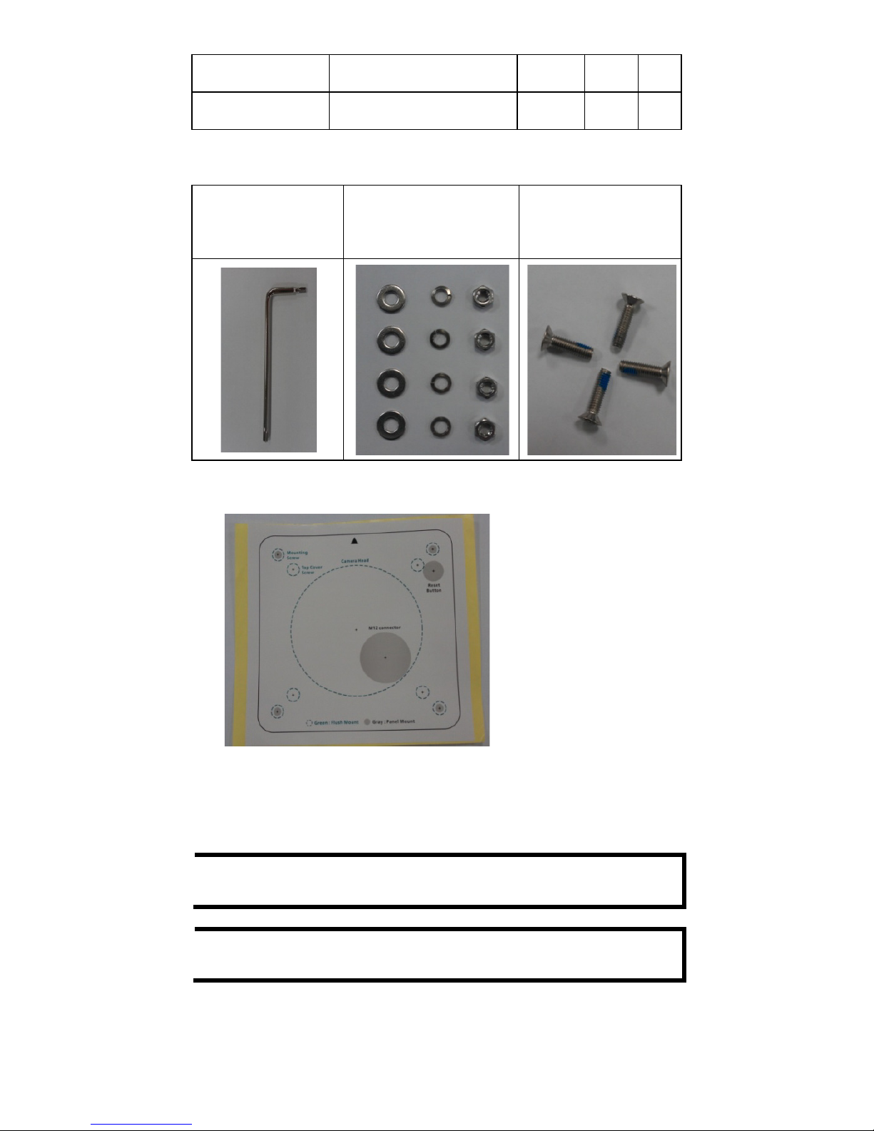
• Screw handle accessory package
Torx screw driver for
attaching/detaching
the upper case
4 sets of nut, gasket and
spring washer for
mouting the camera
4 Nylock flush mount
top cover screws for
mounting the top cover
on the ceiling
• Sticker for camera mounting positions
• Quick Installation Guide
• Document & Software CD (includes User’s Manual, Quick Installation
Guide, and VPort Utility)
• Warranty Statement
NOTE
Check the model name on the VPort’s side label to determine if
the model name is correct for your order.
NOTE
This product must be installed in compliance with your local laws
and regulations.
Page 4

- 4 -
Features
• 1/3” CCD image sensor
• Built-in 3D-Dinterlace for progressive video image
• Camera supports White Balance (ATW/AWC), 3DNR (3D Digital Noise
Reduce), AGC, Slow shutter, AES (Automatic Electrical Shutter) and
BLC (Back Light compensation)
• Minimum illumination is up to 0.02 lux (color)
• Support MJPEG and H.264 Dual Codecs
• Provide 3 video streams for H.264 and MJPEG simultaneously
• Video stream up to 30 frames/sec at SVGA (800x600) resolution
• Video latency under 200 ms
• DynaStream support for network efficiency with dynamic frame rate
change
• SVGA/ Full D1/ 4CIF/ VGA/ CIF/ QCIF resolution
• TCP, UDP and HTTP network transmission mode
• Support DHCP OPT66/67 for automatic configuration from TFTP
server, which can ease the installation efforts in mass installation.
• Support RTSP Streaming
• Support Multicast (IGMP) video streaming
• Support SNMP (V1/V2C/V3) for network system integration and
management
• Support QoS (ToS) for transmission priority
• Built-in web server for easy configuration
• Adjustable frame rate and bit rate control
• Accessible IP filtering
• UPnP Supported
• Compliant with EN50121-3-2 and relevant sections of EN50155
(compliance with IEC 60571)
• 1 10/100BaseT (X) with M12 D-code connector
• IP 66 rain and dust protection with a dehumidifying membrane
• PoE (Power-over-Ethernet, 802.3af) supported
• Optional plastic dome cover model for EN62262 IK10 level vandal
resistant
• Support both ceiling (panel) mounting and embedded (recessed)
mounting
• -25 to 55°C operating temperature for rolling stock environment
• CE, FCC, UL 60950-1
• Built-in Video Motion Detection (VMD)
• Video loss alarm
• Pre, Trigger and post snapshot images supported
• Sequential pre-event snapshot images
• Sequential snapshot images supported
• Support SMTP and FTP for alarm message transmission
• Support HTTP Event Server
• 3-year warranty
Page 5
- 5 -
Product Description of the VPort 16-M12
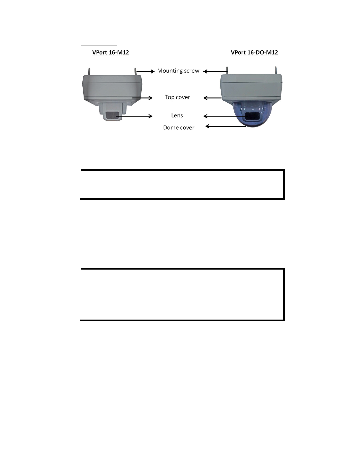
Appearance
• Mounting screw: there are four nylock M4 screws for mounting the
VPort 16-M12 on the wall or ceiling; the external length is about
20mm. These 4 mounting screws can work with the 4 sets of nut,
gasket and spring washer, or directly mount on the screw hole.
NOTE
If the length of the mounting screws is insufficient for your
installation environment, pl
ease contact your Moxa sales
representative for customization service.
• Top cover: This top cover can be removed for tuning the camera lens
position.
• Lens: VPort 16-M12 provides 5 kinds of lens with different focal
length: 3.0mm, 3.6mm, 6mm, 8mm and 16mm, in different auxliary
model name (-CAMxxxxxxx).
• Dome cover: VPort 16-DO-M12 is the model with PC dome cover,
which is vandal-proof with EN62262 (IEC62262) class IK10 level.
NOTE
The color of the dome cover can be customized based on your
installation environment. Please contact your Moxa sales
representative for this cust
omization service. But please note
that
the dome cover will decrease the light transmittance
of the
video image. T
he darker the dome cover is, the greater the
decrease of light transmittance.
Page 6
- 6 -
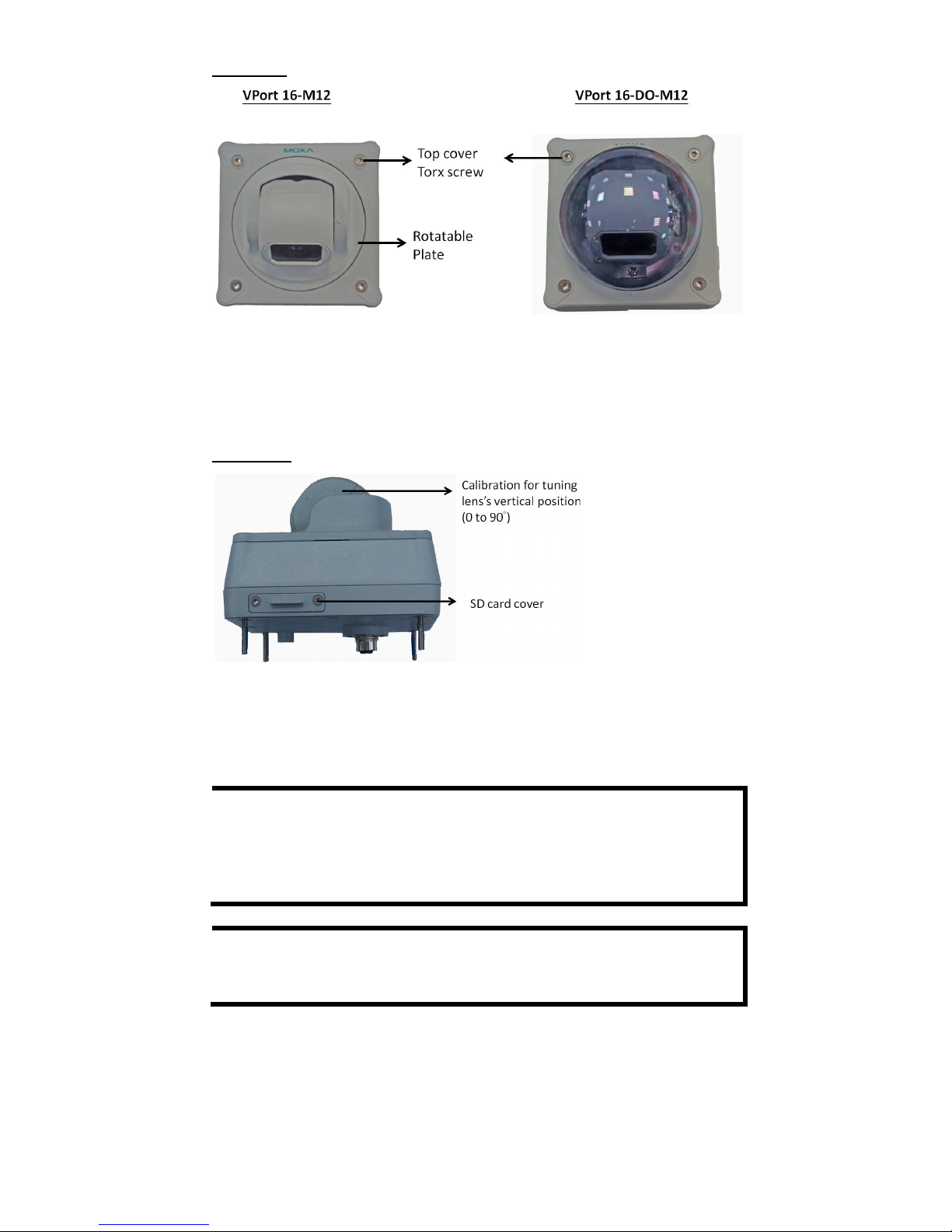
Top View
• Top cover torx screw: To remove the top cover, you can use an L
type torx screw driver.
• Rotatable plate: this plate can be turned manually to fix the
horizontal lens position.
Side View
• Calibration for tuning lens’s vertical position (0 to 90
°): After
tuning the lens vertical position, the user can mark the position with
this calibration for future replacement or mass installation.
• SD card cover: To use an SD card for local storage, the user can
remove this SD card cover with an L-type torx screw driver.
NOTE
The VPort 16-M12 supports a standard SDHC interface. The user
can use
an SD card which is suitable this specification. It is
recommended to use Transcend or Sandisk SD cards. Sandisk
Extreme III SD cards are highly recommended due their
read/write speed.
NOTE
To check if the SD card is mounted successfully, please go to
sys
tem configuration-> Local storage in the VPort’s
web-based manager.
Page 7

- 7 -
Bottom View
• PoE & Etherent M12 connector: A 4-pin M12 A-code connecter for
both PoE power supply (Mode A) and Auto MDI/MDI-X Ethernet
connection.
NOTE
To connect
the VPort 16-M12 series to
the network, you need to
use an
Ethernet cable with a D-code M12 connector and a M12
PoE switch or RJ45 PoE switch
.
M12 D-code to
M12 D-code cable
M12 PoE Switch
(ex. TN-5508-4PoE)
M12 D-code and
RJ45 cable
RJ45 PoE switch
(ex. EDS-P510)
NOTE
The power input rating of VPort 16-M12 is 48V/0.17A, and the
maximum power consumption is about 6.5W.
Page 8

- 8 -
NOTE
The equipment is designed for in building installation only and is
not intended to be connected to exposed (outside plant)
networks.
• Reset button: loosen the screw and use a pointed stick to push down
the reset button to reboot or factor default.
Reboot: press the button onece.
Factory default: press and hold the button for at least 5
seconds.
Top View without top cover and dome cover
• Calibration for tuning the lens horizontal position (0 to 360°):
After tuning the lens horizontal position, the user can mark the
position with this calibration for future replacement or mass
installation.
• 2 screws for fixing the horizontal lens position: there are 2
screws for fixing the horizontal lens position.
• 2 screws for fixing the vertical lens position: there are 2 screws
for fixing the vertical lens position.
Back View without top cover and dome cover
• Dehumidifying membrane: This built-in dehumidifying membrane
is for dissipating moisture trapped inside the camera and keeping
other moisture out.
Page 9

- 9 -
Hardware Installation
Step 1: Open and remove the upper case.
Use the security Torx to loosen the upper case screws.
Step 2: Use the installation sticker for drilling the holes (gray
color for panel mounting, and green color for flush mounting).
Step 3: Put VPort 16-M12 on the holes
Panel Mount
S
crew the hex nuts, gaskets and
washers for fixing it. Then
connect the M12
Ethernet cable.
Flush Mount
Put the camera lens on the hole,
and hide the VPort 16-M12’s body
behind the ceiling.
Page 10

- 10 -
Step 4: Loosen the screws of horizontal and vertical lens position.
Then tune the camera lens position by using the marked
calibration or connecting to the VPort 16-M12’s web console for
viewing the video image. After the lens position is correct, fix the
screws.
Step 5: Fix the top cover and then the installation is complete.
Panel Mount
Screw the 4 top cover screws
back.
Flush Mount
Screw the 4 flush mount top screws
(in accessory) on the top cover
NOTE
The 4 flush mount top cover screws canfix VPort 16-M12’s top
cover on ceiling
s with a maximum 5 mm of thickness. You can
find the M4 screws by yourself, or
contact Moxa for special
support if you require longer top screws.
Software Installation
Step 1: Configure the VPort 16-M12’s IP address
When the VPort 16-M12 is first powered on, the POST (Power On Self Test)
will run for a few moments (about 30 seconds). The network environment
determines how the IP address is assigned.
Network Environment with DHCP Server
For this network environment, the unit’s IP address will be assigned by
the network’s DHCP server. Refer to the DHCP server’s IP address table to
determine the unit’s assigned IP address. You may also use the Moxa
VPort and Ether Device Configurator Utility (edscfgui.exe), as described
below:
Using the Moxa VPort and EtherDevice Configurator Utility
(edscfgui.exe)
1. Run the edscfgui.exe program to search for the VPort. After the
utility’s window opens, you may also click on the Search button
to initiate a search.
Page 11

- 11 -
2. When the search has concluded, the Model Name, MAC address, IP
address, serial port, and HTTP port of the VPort will be listed in the
utility’s window.
3. Users can double click the selected VPort, or use the IE web browser
to access the VPort’s web-based manager (web server).
Non DHCP Server Network Environment
If your VPort 16-M12 is connected to a network that does not have a
DHCP server, then you will need to configure the IP address manually.
The default IP address of the VPort 16-M12 is 192.168.127.100 and the
default subnet mask is 255.255.255.0. Note that you may need to change
your computer’s IP address and subnet mask so that the computer is on
the same subnet as the VPort.
To change the IP address of the VPort manually, access the VPort’s web
server, and then navigate to the System Configuration
Network
General page to configure the IP address and other network settings.
Check the Use fixed IP address to ensure that the IP address you
assign is not deleted each time the VPort is restarted.
Step 2: Accessing the VPort 16-M12’s web-based manager
Type the IP address in the web browser’s address input box and then
press enter.
Step 3: Install the ActiveX Control Plug-in
A security warning message will appear the first time you access the
VPort’s web-based manager. The message is related to installing the
VPort AcitveX Control component on your PC or notebook. Click Yes to
install this plug-in to enable the IE web browser for viewing video images.
Page 12

- 12 -
NOTE
For Windows XP SP2 or above operating systems, the ActiveX
Control component will be
blocked for system security reasons.
In this case, the VPort’s security warning message window may
not appear. Users should unlock the ActiveX control blocked
function or disable the security configuration to enable the
installation of the VPort’s ActiveX Control component.
Step 4: Access the homepage of VPort 16-M12’s web-based
manager.
After installing the ActiveX Control component, the homepage of the
VPort 16-M12’s web-based manager will appear. Check the following
items to make sure the system was installed properly:
1. Video Images
2. Video Information
Step 5: Access the VPort’s system configuration.
Click on System Configuration to access the overview of the system
configuration to change the configuration. Model Name, Server Name,
IP Address, MAC Address and Firmware Version appear in the green
bar near the top of the page. Use this information to check the system
information and installation.
For details of each configuration, check the User’s Manual on the software
CD.
Page 13

- 13 -
Wiring Requirements
ATTENTION
Safety First!
Be sure to disconnect the power cord before installing and/or
wiring your Moxa VPort 16
-M12.
Calculate the maximum possible current in each power wire and
common wire. Observe all electrical codes dict
ating the
maximum current allowable for each wire size.
If the current goes above the maximum ratings, the wiring could
overheat, causing serious damage to your equipment.
You should also pay attention to the following:
• Use separate paths to route wiring for power and devices. If power
wiring and device wiring paths must cross, make sure the wires are
perpendicular at the intersection point.
• You can use the type of signal transmitted through a wire to
determine which wires should be kept separate. The rule of thumb is
that wiring that shares similar electrical characteristics can be
bundled together.
• Keep input wiring and output wiring separated.
• It is strongly advised that you label wiring to all devices in the system
when necessary.
Dimensions
Front View
Front View (Dome Model)
Top View
Bottom View
Page 14

- 14 -
Side View
Side View (Dome Model)
Specifications
Camera
Sensor
1/3” CCD
Lens
3, 3.6, 6, 8, and 16 mm fixed focal length
Angle of view 3.0 mm / F2.0: 120°
3.6 mm / F2.0: 92°
6.0 mm / F1.8: 53°
8.0 mm / F2.0: 40°
16 mm / F2.5: 19°
Modulation
NTSC or PAL
Camera lens angle
pan 360°, tilt 90° (contolled manually)
Illumination
(Low light sensitvity)
0.02 Lux at F2.0, color
Synchronization
Internal
White Balance
ATW/ AWC
Electronic Shutter
NTSC: 1/60 to 1/120,000 sec.
PAL:1/50 to 1/120,000 sec.
S/N Ratio
50 dB (MIN) / 58 dB (TYP) (Gamma, Aperture,
AGC, OFF)
AGC Control
On/ Off
Flickerless Control
On/ Off
Backlight Compensation
On/ Off
Auto Exposure/ Auto Iris
On/ Off
Image Rotation
Flip, Mirror, and 180° rotation
Image Setting
Manually tuning with brightness, saturation,
contrast and hue
Built-in 3D-deinterlacing and 3D-DNR (3D
digital noise reduction)
Horizontal Resolution
540 TVL
Video
Video Compression
H.264 (ISO/IEC 14496-10) or MJPEG
Video Output
Via Ethernet port
Video Streams
Maximum of 3 video streams (2 H.264 and 1
MJPEG)
Page 15

- 15 -
Video Resolution and FPS (Frame per second):
NTSC
PAL
Size
Max. FPS
Size
Max. FPS
QCIF
176 x 112
30
176 x 144
25
CIF
352 x 240
30
352 x 288
25
VGA
640 x 480
30
640 x 480
25
4CIF
704 x 480
30
704 x 576
25
Full D1
720 x 480
30
720 x 576
25
SVGA
800 x 600
30
800 x 600
25
Video Viewing
DynaStream™ supported for changing the
video frame rate automatically
Adjustable image size and quality
Timestamp and text overlay
Maximum of 10 simultaneous unicast
connections
Network
Protocols
TCP, UDP, HTTP, SMTP, FTP, Telnet, NTP, DNS,
DHCP, UPnP, RTP, RTSP, ICMP, QoS,
SNMPv1/v2c/v3, DDNS, TFTP, OPT 66/67
Ethernet
1 10/100BaseT(X) Ethernet port, M12 D-code
connector
Local Storage
SD Socket
Standard SD socket (SDHC)
Power Requirements
Input
Power-over-Ethernet (IEEE 802.3af)
Consumption
Maximum 6.5W
Physical Characteristics
Housing
Metal and glass, optional PC dome cover,
IP66-rated
Dehumidifying
Membrane
GORE protective vent
Dimensions
Standard model: 125 x 125 x 109.1 mm (5.6 x
5.6 x 4.3in)
Dome model: 125 x 125 x 120.7 mm (5.6 x 5.6
x 4.8 in)
Weight Standard model: 840 g
Dome model: 850 g
Installation
Surface (ceiling) or flush (recessed) mounting
Environmental Limits
Operating Temperature
-25 to 55°C (-13 to 131°F)
Storage Temperature
-40 to 85°C (-40 to 185°F)
Ambient Relative
Humidity
5 to 95% (non-condensing)
Page 16

- 16 -
Regulatory Approvals
Safety
UL60950-1
EMI
FCC Part 15 Subpart B Class A,
EN 55022 Class A
EMS
EN61000-4-2 (ESD), Level 3
EN61000-4-3 (RS), Level 3
EN61000-4-4 (EFT), Level 3
EN61000-4-5 (Surge), Level 3
EN61000-4-6 (CS), Level 3
EN61000-4-8
EN61000-4-11
Rolling Stock
EN 50155:2007 compliance (shock, vibration,
temperature, EMC)
Shock
IEC60068-2-27
Freefall
IEC60068-2-32
Vibration
IEC60068-2-6
Vandal resistance
IEC62262, Class IK10 (dome model)
MTBF (Mean-time
between failure)
59,314 hours (Telcordia (Bellcore), 25°C)
Warranty
3 year
Alarm Features
Intelligent Video: Tamper alarm (Pending)
Video Motion Detection: Includes sensitivity tuning
Video Loss: Video loss alarm
Scheduling: Daily repeat timing schedule
Imaging: JPEG snapshots for pre/trigger/post alarm images
Custom Alarms: HTTP event servers for setting customized alarm actions
Pre-alarm Buffer: 9 MB video buffer for JPEG snapshot images
Local Video Recording: Triggered by the alarm within the given time
period
Security
User level password protection
IP address filtering
Minimum Viewing System Requirements
Pentium 4, 2.4 GHz
512 MB of memory
Windows XP/2000 with SP4 or above
Internet Explorer 6.x or above
DirectX 9.0c or above
Software Development Kit
VPort SDK PLUS
Includes CGI commands, ActiveX Control, and
API library for customized applications or
system integration for third-party developer
Standard
ONVIF
Page 17

- 17 -
Technical Support Contact Information
www.moxa.com/support
Moxa Americas:
Toll
-free: 1-888-669-2872
Tel:
1-714-528-6777
Fax:
1-714-528-6778
Moxa China (Shanghai office):
Toll
-free: 800-820-5036
Tel:
+86-21-5258-9955
Fax:
+86-21-5258-5505
Moxa Europe:
Tel:
+49-89-3 70 03 99-0
Fax:
+49-89-3 70 03 99-99
Moxa Asia-Pacific:
Tel:
+886-2-8919-1230
Fax:
+886-2-8919-1231
 Loading...