

Page 1

V460 Series Hardware User ’s Manual
First Edition, March 2008
www.moxa.com/product
Moxa Inc.
Tel: +886-2-2910-1230
Fax: +886-2-2910-1231
Web:
www.moxa.com
Moxa Technical Support
Worldwide:
support@moxa.com
The Americas:
support@usa.moxa.com
Page 2

V460 Series Hardware User’s Manual
Any software described in this manual is furnished under a license agreement and may be used only in
accordance with the terms of that agreement.
Copyright Notice
Copyright © 2008 Moxa Inc.
All rights reserved.
Reproduction without permi ssion is pr ohibited.
Trademarks
MOXA is a registered trademark of Moxa Inc.
All other trademarks or registered marks in this manual belong to their respective manufacturers.
Disclaimer
Information in this document is subject to change without notice and does not represent a commitment on the
part of Moxa.
Moxa provides this document “as is,” without warranty of any kind, either expressed or implied, including, but
not limited to, its particular purpose. Moxa reserves the right to make improvements and/or changes to this
manual, or to the products and/or the programs described in this manual, at any time.
Information provided in this manual is intended to be accurate and reliable. However, Moxa assumes no
responsibility for its use, or for any infringements on the rights of third parties that may result from its use.
This product might include unintentional technical or typographical errors. Changes are periodically made to the
information herein to correct such errors, and these changes are incorporated into new editions of the
publication.
Page 3

Table of Contents
Chapter 1 Introduction..................................................................................................1-1
Overview.................................................................................................................................. 1-2
Package Checklist.................................................................................................................... 1-2
Product Features ...................................................................................................................... 1-3
Product Hardware Specifications............................................................................................. 1-4
Hardware Block Diagrams....................................................................................................... 1-6
Chapter 2 Hardware Introduction.................................................................................2-1
Appearance.............................................................................................................................. 2-2
Dimensions (unit = mm).......................................................................................................... 2-5
LED Indicators......................................................................................................................... 2-5
Power On/Off Button...............................................................................................................2-6
Reset Button............................................................................................................................. 2-6
Real Time Clock...................................................................................................................... 2-6
Placement Options................................................................................................................... 2-7
Wall or Cabinet .......................................................................................................... 2-7
DIN-Rail Mounting.................................................................................................... 2-7
Chapter 3 Hardware Connection Description .............................................................3-1
Wiring Requirements............................................................................................................... 3-2
Connecting the Power ................................................................................................ 3-2
Grounding the Unit..................................................................................................... 3-3
Connecting to a Display........................................................................................................... 3-3
Connecting to a Keyboard and Mouse.....................................................................................3-4
Connecting to the Network...................................................................................................... 3-4
Connecting to a Serial Device.................................................................................................. 3-5
Connecting to the unmanaged switch ports (V466 only).........................................................3-6
PCMCIA (V462 only).............................................................................................................. 3-6
Connecting to the DI/DO (V468 only)..................................................................................... 3-6
Digital Input Wiring................................................................................................... 3-7
Digital Output Wiring ................................................................................................ 3-7
Installing a Memory Module ................................................................................................... 3-7
Inserting a CompactFlash Card................................................................................................ 3-8
USB Hosts ............................................................................................................................... 3-9
Audio Interface...................................................................................................................... 3-10
Chapter 4 BIOS Setup ...................................................................................................4-1
Entering the BIOS Setup Utility .............................................................................................. 4-2
Modifying the BIOS Main Settings......................................................................................... 4-2
Basic Configuration.................................................................................................... 4-2
System Security.......................................................................................................... 4-3
Advanced Settings ................................................................................................................... 4-4
Removable Device/Hard Disk/Cd-ROM Boot Priority.............................................. 4-4
First / Second / Third Boot Device............................................................................. 4-4
Boot Other Device...................................................................................................... 4-4
Modifying Advanced BIOS Settings.......................................................................... 4-4
Advanced Chipset Settings......................................................................................... 4-6
Page 4

PnP/PCI Configurations............................................................................................. 4-8
Peripherals ............................................................................................................................... 4-9
Power......................................................................................................................................4-11
Hardware Monitor.................................................................................................................. 4-12
Load Defaults......................................................................................................................... 4-12
Exiting the BIOS Setup.......................................................................................................... 4-13
Upgrading the BIOS .............................................................................................................. 4-15
Page 5

1
1
Chapter 1 Introduction
Thank you for purchasing the Moxa V460 series x86-based industrial ready-to-run embedded
computer. This product’s features include RS-232/422/485 serial ports, dual or quad 10/100 Mbps
Ethernet ports, VGA output, a CompactFlash socket for mass storage expansion, PS/2 connector
for keyboard/mouse usage, four USB 2.0 ports that support system boot, mass storage disk
expansion, or other peripherals, 8 di gi t a l inp ut chan nel s a n d 8 di gi t a l output channels, and input
channels with 3 KV protection (V468), 8 10/10 0 M bps unmanaged switch ports (V466), and
PCMCIA slot (V462). The V460 series is based on the AMD low power consumption solution,
which makes it suitable for various industrial and harsh applications such as SCADA, factory
automation, and applications that require an onsite display or monitor. The x86 architecture and
friendly Windows embedded platform provide an integrated powerful tool for handling data. The
V460 can be used as a field host and control center for on-site applications that transfer or relay
information.
This manual introduces the hardware of the V460 series embedded computers. After a brief
introduction of the hardware features, the manual focuses on installation and hardware
configuration with device interfaces.
In this chapter, we cover the following topics:
Overview
Package Checklist
Product Features
Product Hardware Specifications
Hardware Block Diagrams
Page 6

V460 Series Hardware User’s Manual Introduction
1-2
Overview
The V460 series of x86 ready-to-run embedded computers is designed around the AMD LX800
and Geode chipset, which exhibits low power consumption and high reliability. In additio n to the
usual computer peripherals, the V460 integrates dual or quad LAN ports, 4 USB 2.0 hosts, and 4
serial ports, making the V460 into an ideal industrial embedded computer for handling not only
communication tasks, but also applications that require advanced computin g power. In addition,
all output and information can be displayed onscreen through the built-in VGA interface. The
V460 series offers a variety of I/O options for use in a variety of applications and vertical markets.
The on-board CompactFlash and DDR SDRAM provide ample storage capacity, and the
Windows-based operating system comes pre-installed and ready-to-run, providing a Windows-like
environment for easy software development. Software written for desktop PCs can be easily ported
to the V460 using a common complier, which means that programmers do not need to spend a lot
of time modifying existing software code. In addition, the operating system, device drivers, and
user-developed software can all be stored in the pre-installed CompactFlash memory Card to
enhance system reliability.
Package Checklist
V462-CE
x86 Ready-to-Run Embedded Computer with AMD LX 800, VGA, Dual LANs, 4 Serial Ports,
CompactFlash, PCMCIA, USB, Audio, WinCE 6.0.
V464-CE
x86 Ready-to-Run Embedded Computer with AMD LX 800, VGA, Quad LANs, 4 Serial Ports,
CompactFlash, USB, Audio, WinCE 6.0.
V466-CE
x86 Ready-to-Run Embedded Computer with AMD LX 800, VGA, Quad LANs, 4 Serial Ports, 8
Unmanaged Switch Ports, CompactFlash, USB, Audio, WinCE 6.0.
V468-CE
x86 Ready-to-Run Embedded Computer with AMD LX 800, VGA, Quad LANs, 4 Serial Ports,
8DI, 8DO, CompactFlash, USB, Audio, WinCE 6.0.
V462-XPE
x86 Ready-to-Run Embedded Computer with AMD LX 800, VGA, Dual LANs, 4 Serial Ports,
CompactFlash, PCMCIA, USB, Audio, WinXP embedded.
V464-XPE
x86 Ready-to-Run Embedded Computer with AMD LX 800, VGA, Quad LANs, 4 Serial Ports,
CompactFlash, USB, Audio, WinXP embedded.
V466-XPE
x86 Ready-to-Run Embedded Computer with AMD LX 800, VGA, Quad LANs, 4 Serial Ports, 8
Unmanaged Switch Ports, CompactFlash, USB, Audio, WinXP embedded.
V468-XPE
x86 Ready-to-Run Embedded Computer with AMD LX 800, VGA, Quad LANs, 4 Serial Ports,
8DI, 8DO, CompactFlash, USB, Audio, WinXP embedded.
Page 7

V460 Series Hardware User’s Manual Introduction
1-3
All models of the V462/464/466/468 series are shipped with the following items:
y 1 V460 Series Embedded Computer
y Quick Installation Guide
y Document & Software CD
y Ethernet Cable: RJ45 to RJ45 cross-over cable, 100 cm
y PS2 to KB/MS Y type Cable
y Din-rail Kit
y Product Warranty Statement
Optional Accessories
Switching Power Adaptor: 60W, 24 VDC output, 100 to 240 VAC input, power cord must be
ordered separately.
y Power Cords:
Power cord with Australia Plug
Power Cord with UK Plug
Power Cord with Euro Plug
Power Cord with US Straight Plug
NOTE: Notify your sales representative if any of the above items are missing or damaged.
Product Features
y AMD Geode LX 800@0.9W CPU, 500 MHz
y Built-in 256 MB DDR SDRAM (512MB for XPE version)
y Built-in 256 MB Industrial DOM to store OS (1GB for XPE version)
y 512K battery backup SRAM
y 2 RS-232 and 2 RS-232/422/485 serial ports
y Serial port 3 and port 4 support ANY BAUD RATE
y 2 or 4 10/100 Mbps Ethernet ports for network red u ndancy
y 8 unmanaged switch ports
y 8 + 8 DI/DO with 3 KV isolation protection
y CompactFlash socket for storage expansion
y 4 USB 2.0 hosts that support system boot up
y LED indicators for Power, Battery, Storage
y Ready-to-run WinCE 6.0 or XP embedded platfo rm
y Din-rail and Wall mount installation supported
y Robust, fanless design
Page 8
V460 Series Hardware User’s Manual Introduction
1-4
Product Hardware Specifications
System
CPU
AMD Geode LX 800@0.9W processor with 128K L2 Cache, 500
MHz
System Chipset
AMD CS5536 chipset
FSB
400 MHz
Expansion Bus
On-board PC/104-Plus
BIOS
4 mega-bit Flash BIOS, supporting Plug & Play, APM 1.2
System Memory
200-pin SO-DIMM socket x 1 with built-in 256 MB DDRSupport
DDR400 up to 1GB
SRAM
512K SRAM, battery backup
OS
Windows CE 6.0, WindowsXP Embedded
Display
Graphics Controller
CPU Integrated 2D graphics
Display Interface
CRT Interface for VGA output
Network Communication
LAN
V462: Auto-sensing 10/100 Mbps x 2, RJ45 connector
V464: Auto-sensing 10/100 Mbps x 4, RJ45 connector
V466: Auto-sensing 10/100 Mbps x 4, RJ45 connector
V468: Auto-sensing 10/100 Mbps x 4, RJ45 connector
LAN Controller
Realtek RTL8100C
Protection
Built-in 1.5KV magnetic isolation protection
Serial Communication
Serial Ports
Ports 1 and 2: RS-232, DB9 male
Ports 3 4: RS-232/422/485, software-selectable, DB9 male
RS-232 signals: TxD, RxD, DTR, DSR, RTS, CTS, DCD, GND
RS-422 signals: TxD+, TxD-, RxD+, RxD-, GND
RS-485-4w signals: TxD+, TxD-, RxD+, RxD-, GND
RS-485-2w signals: Data+, Data-, GND
Protection
Built-in 15 KV ESD protection for all signals
Data bits
5, 6, 7, 8
Stop bits
1, 1.5, 2
Parity
None, Even, Odd, Space, Mark
Flow Control
RTS/CTS, XON/XOFF, RS-485 ADDC™
Speed
50 bps to 921.6 Kbps; ports 3 and 4 support ANY BUAD RATE
Connector Type
D-Sub male 9-pin connector
Unmanaged Switch Communication (V466 only)
Switch Port
Unmanaged 10/100 Mbps switch ports x 8
Page 9
V460 Series Hardware User’s Manual Introduction
1-5
Digital Input (V468 only)
Input Channels
8, source type
Digital input levels
Dry contact:
Logic level 0: Close to GND
Logic level 1: Open
Wet contact:
Logic level 0: +3V max
Logic level 1: +10 to +30V (COM to DI)
Protection
3 KV optical isolation protection
Connector Type
10-pin screw terminal block (8 points / COM / GND)
Digital Output (V468 only)
Output Channels
8, sink type
On-state Voltage
24 VDC nominal, open collector t o 30 V
Output Current Rating
Max. 200 mA per channel
Protection:
3 KV optical isolation protection
Connector Type
9-pin screw terminal block
Other Peripherals
USB
USB 2.0 compliant hosts x 4, type A connector, supporting system
boot up
Audio
AC97 audio, supporting speaker-out interface
KB/MS
1 PS/2 interface supporting standard PS/2 keyboard and PS/2 mouse
via Y-type cable
Watchdog Timer
Supports 1 to 255 level time interval system reset, software
programmable
RTC
Comes with battery backup
PCMCIA
Cardbus card and 16-bit PCMCIA 2.1/ JEIDA 4.2 card (V462 only)
LEDs
System
Power x 1, Ready x 1, Storage x 1
LAN
V462: 10M/Link x 2 (on connector), 100M/Link x 2 (on connector)
V464: 10M/Link x 4 (on connector), 100M/Link x 4 (on connector)
V466: 10M/Link x 4 (on connector), 100M/Link x 4 (on connector)
V468: 10M/Link x 4 (on connector), 100M/Link x 4 (on connector)
Power Requirements
Power Input
9 to 36 VDC, 3-pin terminal block (V+, V-, SG)
Power Consumption
2820 mA @ 36V, 730 mA @ 9V
Physical Properties
Board Form Factor
EPIC
Dimensions (WxDxH):
260 x 135 x 50 mm (without wall mount kit)
Weight
1.36 kg
Construction Material
Aluminum
Mounting Options
DIN-rail, wall mounting
Page 10
V460 Series Hardware User’s Manual Introduction
1-6
Environmental Limits
Operating Temperature
-10 to 60°C (14 to 140°F), 5 to 95% RH
-40 to 75°C (-40 to 167°F) is optional for -T models
Storage Temperature
-20 to 80°C (-4 to 176°F), 5 to 95% RH
-40 to 85°C (-40 to 185°F) is optional for -T models
Regulatory Approvals
EMC
FCC, CE (Class A)
Safety
UL, cUL, LVD
Other
RoHS, WEEE
Warranty
5 years
Hardware Block Diagrams
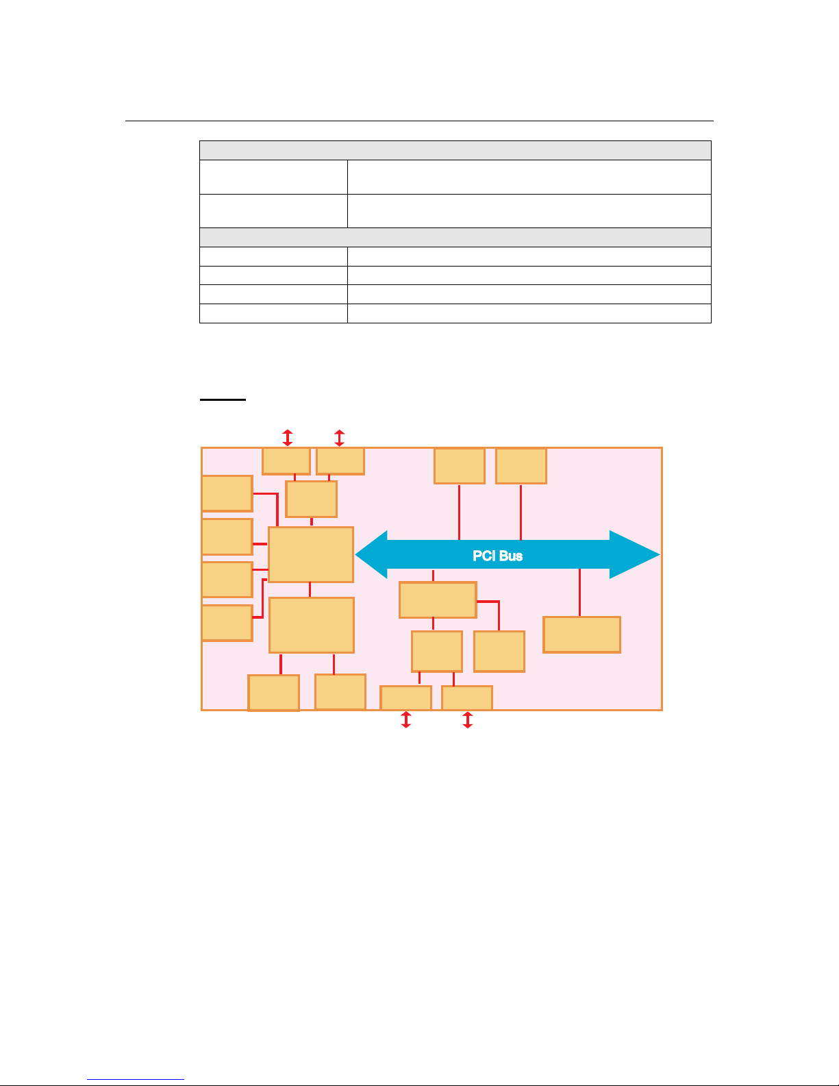
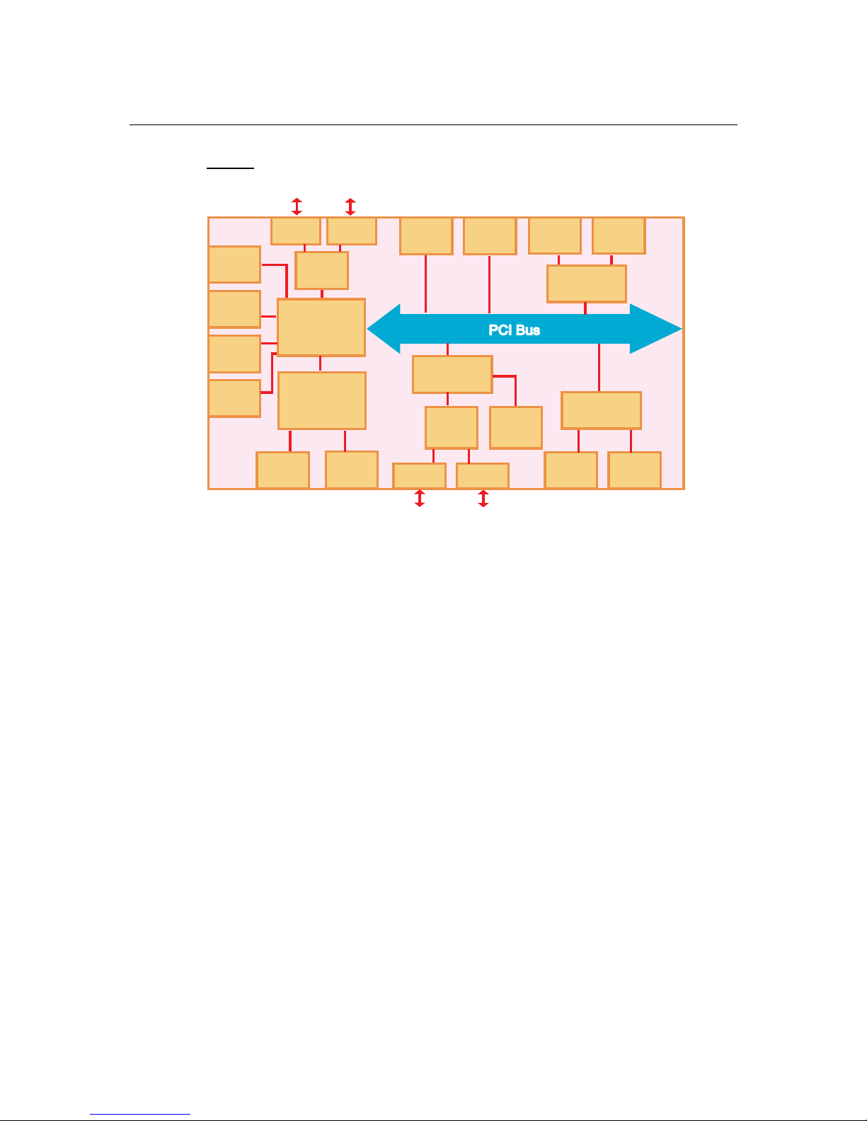
V462
AMD
CS5536
DDR
SDRAM
VGA
USB
Host x 4
CF
Function
Super
I/O
IDE
Audio
ISA Bridge
LAN1 LAN2
PCMCIA
MOXA
UART
ASIC
Battery
Backup
SRAM
RS-232
RS-232/422/485
AMD
LX800
CPU
RS-232
Serial
Port 1
Serial
Port 2
Serial
Port 3
Serial
Port 4
Page 11
V460 Series Hardware User’s Manual Introduction
1-7
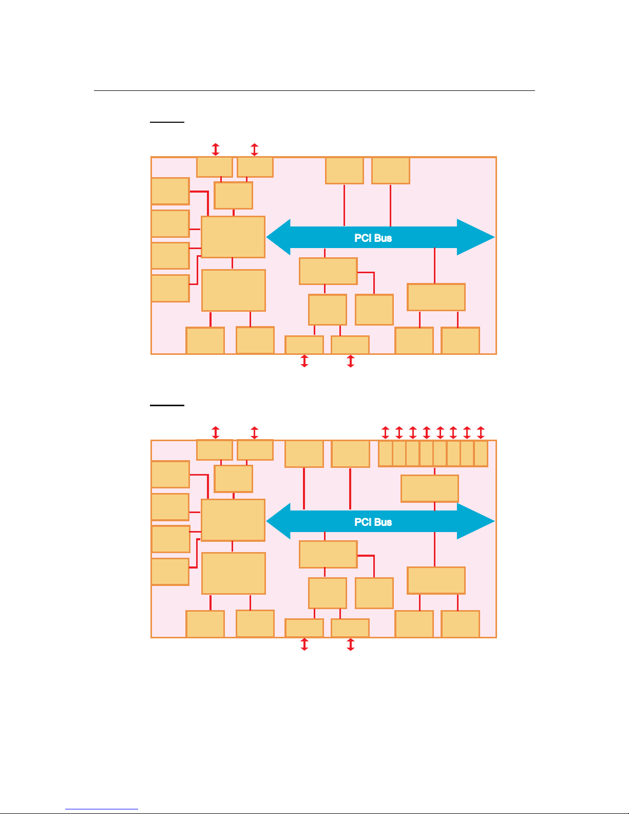
V464
AMD
CS5536
DDR
SDRAM
VGA
Super
I/O
IDE
Audio
ISA Bridge
LAN1 LAN2
MOXA
UART
ASIC
Battery
Backup
SRAM
RS-232/422/485
AMD
LX800
CPU
LAN
Controller
LAN3 LAN4
USB
Host x 4
CF
Function
RS-232 RS-232
Serial
Port 1
Serial
Port 2
Serial
Port 3
Serial
Port 4
V466
AMD
CS5536
DDR
SDRAM
VGA
USB
Host x 4
CF
Function
Super
I/O
IDE
Audio
ISA Bridge
LAN1 LAN2
MOXA
UART
ASIC
Battery
Backup
SRAM
RS-232
RS-232/422/485
AMD
LX800
CPU
LAN
Controller
LAN3 LAN4
Switch
Controller
7 85 61 2 3 4
Switch Port x 8
Serial
Port 1
Serial
Port 2
RS-232
Serial
Port 3
Serial
Port 4
Page 12
V460 Series Hardware User’s Manual Introduction
1-8
V468
AMD
CS5536
DDR
SDRAM
VGA
CF
Function
Super
I/O
IDE
Audio
ISA Bridge
LAN1 LAN2
MOXA
UART
ASIC
Battery
Backup
SRAM
RS-232/422/485
AMD
LX800
CPU
LAN
Controller
LAN3 LAN4
CPLD
DI x 8 DO x 8
USB
Host x 4
RS-232
Serial
Port 1
Serial
Port 2
RS-232
Serial
Port 3
Serial
Port 4
Page 13

2
2
Chapter 2 Hardware Introduction
The V460 embedded computers are compact and rugged, making them suitable for industrial
applications. The LED indicators allow users to monitor performance and identify trouble spots
quickly, the multiple serial ports can be used to connect a variety of devices, the PCMCIA slot
(V462) can be used for a variety of applications, the 8 switch ports (V466) can be used to connect
different nodes via Ethernet to enlarge your automation network scope, and the 8+8 DI/DO (V468)
enables the embedded computer to be used as an on-site center to gather signals and alarms from
field equipment and convert protocols to ease the loading on other management nodes.
The V460 computers have a reliable and stable hardware platform that lets you devote the bulk of
your time to application development. In this chapter, we provide basic information about the
embedded computer’s hardware and its various components. The following topics are covered:
Appearance
Dimensions (unit = mm)
LED Indicators
Power On/Off Button
Reset Button
Real Time Clock
Placement Options
¾
Wall or Cabinet
¾
DIN-Rail Mounting
Page 14
V460 Series Hardware User’s Manual Hardware Introduction
2-2
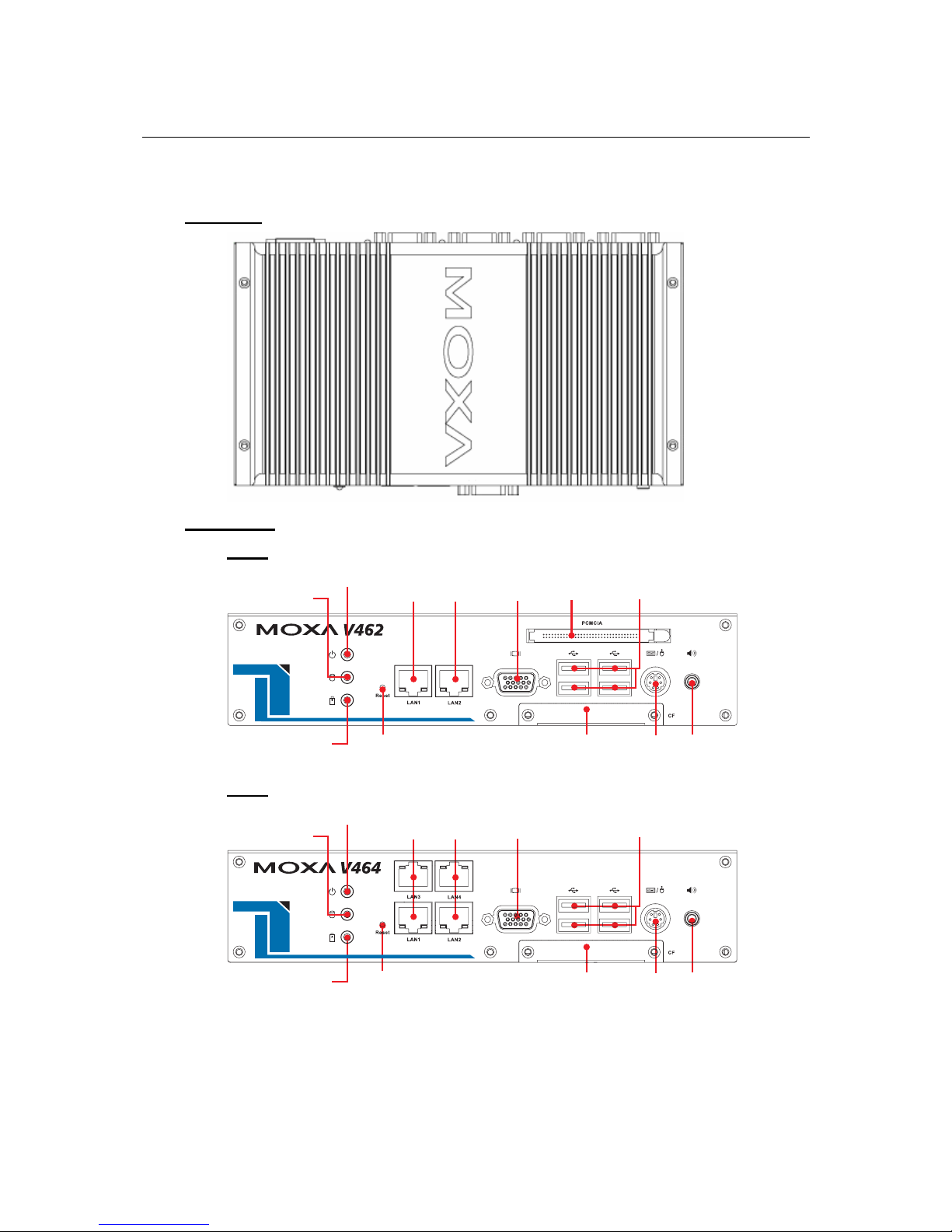
Appearance
Top View
Front View
V462
10/100 Mbps
Ethernet x 2
Power LED
SRAM Battery
Status LED
Storage LED
VGA
PS/2
PCMCIA
Socket USB 2.0 Host x 4
CompactFlash
Socket
Audio Line Out
Reset
V464
10/100 Mbps
Ethernet x 4
Power LED
SRAM Battery
Status LED
Storage LED
VGA
PS/2
USB 2.0 Host x 4
CompactFlash
Socket
Audio Line Out
Reset
Page 15
V460 Series Hardware User’s Manual Hardware Introduction
2-3
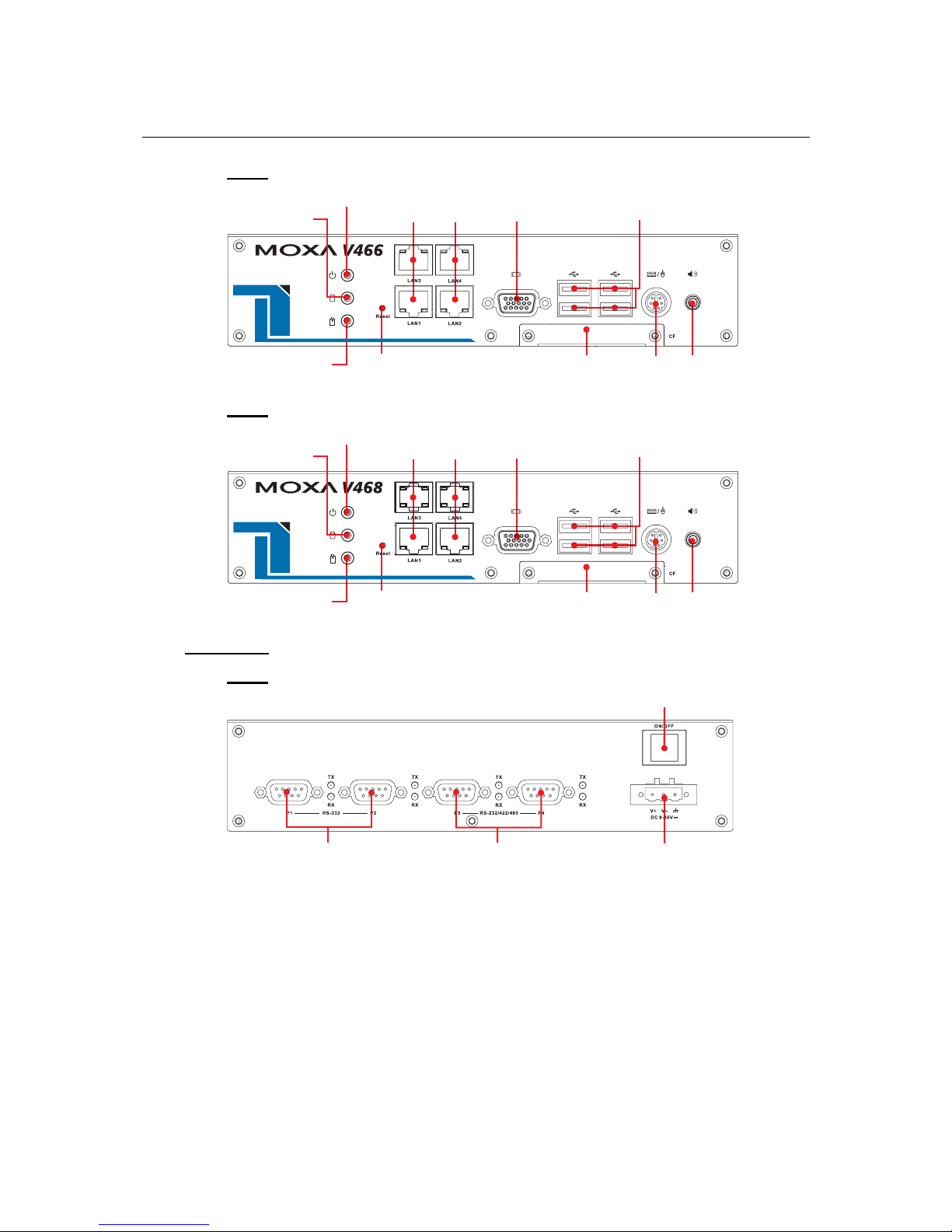
V466
10/100 Mbps
Ethernet x 4
Power LED
SRAM Battery
Status LED
Storage LED
VGA
PS/2
USB 2.0 Host x 4
CompactFlash
Socket
Audio Line Out
Reset
V468
10/100 Mbps
Ethernet x 4
Power LED
SRAM Battery
Status LED
Storage LED
VGA
PS/2
USB 2.0 Host x 4
CompactFlash
Socket
Audio Line Out
Reset
Rear View
V462
RS-232
Serial Ports x 2
RS-232/422/485
Serial Ports x 2
Power Switch
Power Input
9-36 VDC
Page 16

V460 Series Hardware User’s Manual Hardware Introduction
2-4
V464
RS-232
Serial Ports x 2
RS-232/422/485
Serial Ports x 2
Power Switch
Power Input
9-36 VDC
V466
RS-232
Serial Ports x 2
RS-232/422/485
Serial Ports x 2
Power Switch
Power Input
9-36 VDC
10/100 Mbps Ethernet Switch Ports x 8
V468
RS-232
Serial Ports x 2
RS-232/422/485
Serial Ports x 2
Power Switch
Power Input
9-36 VDC
DI x 8
DO x 8
Page 17

V460 Series Hardware User’s Manual Hardware Introduction
2-5
Dimensions (unit = mm)
223
120.5
57
LED Indicators
The LED indicators located on the front panel of the V460 series are listed in the following table.
LED Name LED Color LED Function
Green Power is on
Power
Off No power input or any other power error exists
Red Battery is dead or malfunctioning
Battery
Off Battery is operating normally
Yellow / Blinking Storage device is active (data is being read or written)
Storage
Off Storage device is idle
Green Lit when 10 Mbps Ethernet link is active (Off when
inactive).
Green Lit when 100 Mbps Ethernet link is active (Off when
inactive).
LAN
Orange Lit when data is transmitting.
Please note that the V462 has 2 RJ45 connectors, whereas the V464, V466, and V468 have 4 RJ45
connectors.
Page 18

V460 Series Hardware User’s Manual Hardware Introduction
2-6
Power On/Off Button
The power on/off button is located above the power input terminal block. The button supports the
ATX power on/off function. By default, the button is set for instant off. You may also configure
the button for delay 4 seconds to guard against shutting down the power uninten tionally. In this
case, you must press the power button continuously for at least 4 seconds to shut off the power.
For detailed configuration instructions, please see Chapter 4: BIOS Setup towards the end of this
manual.
Reset Button
Press the Reset Button continuously for at least 5 seconds to load the factory default configuration.
After the factory default configuration has been loaded, the system will reboot automatically. The
Ready LED will blink on and off for the first 5 seconds, and then maintain a steady glow once the
system has rebooted.
We recommend that you only use this function if the software is not working properly and you
want to load factory default settings. The Reset to Default functionality is not design ed to hard
reboot the V460 Series.
ATTENTION
Reset to Default preserves user’s data
The Reset to Default functionality will NOT format the user directory and erase the user’s data.
Pressing the Reset to default functionality will only load the configuration file. Other user data
will not be deleted from the Flash ROM.
Real Time Clock
The V460’s real time clock is powered by a lithium battery. We strongly recommend that you do
not replace the lithium battery without help from a qualified Moxa support engineer. If you need to
change the battery, contact the Moxa RMA service team.
WARNING
There is a risk of explosion if the battery is replaced by an incorrect type.
Page 19

V460 Series Hardware User’s Manual Hardware Introduction
2-7
Placement Options
Wall or Cabinet
The V460 computers have wall-mount ears for attaching to a wall or the inside of a cabinet. Use
screws to attach the V460 to a wall or cabinet, as illustrated in the following figure.
NOTE
Before tightening the screws into the wall, make sure the screw head and shank size are suitable
by inserting the screw into one of the keyhole-shaped apertures of the wall mounting plates.
DIN-Rail Mounting
An aluminum DIN-Rail Mounting Kit comes standard with the V460 series computers. The V460
can be mounted on a DIN-Rail either vertically or horizontally by changing the screw holes used
for the stiff metal spring. If you need to reattach the DIN-Rail kit to the V460 series, make sure the
stiff metal spring is situated towards the top, as shown in the following figures.
STEP1: Insert the top of the DIN-Rail into the
slot just below the stiff metal spring.
STEP2: The DIN-Rail attachment unit will
snap into place as shown.
metal
spring
DIN-Rail
metal
spring
DIN-Rail
To remove the V460 series from the DIN-Rail, simply reverse Steps 1 and 2.
Page 20

3
3
Chapter 3 Hardware Connection Description
The V460 series embedded computers are equipped with multiple connection types. VGA, RJ45
Ethernet connectors, serial ports, PCMCIA slot (V464), 8+8 DI/DO (V468) and unmanaged
switching ports (V466) are built into the V460. The V460 also has a CompactFlash socket for
storage expansion, USB ports for additional device and storage options, and an audio output port.
The ready-to-run Windows Embedded operating system gives you the freedom to develop custom
applications for any type of industrial automation application.
In this chapter, we describe how to connect the embedded computer to the network and to various
devices. The following topics are covered:
Wiring Requirements
¾ Connecting the Power
¾
Grounding the Unit
Connecting to a Display
Connecting to a Keyboard and Mouse
Connecting to the Network
Connecting to a Serial Device
Connecting to the unmanaged switch ports (V466 only)
PCMCIA (V462 only)
Connecting to the DI/DO (V468 only)
¾ Digital Input Wiring
¾
Digital Output Wiring
Installing a Memory Module
Inserting a CompactFlash Card
USB Hosts
Audio Interface
Page 21

V460 Series Hardware User’s Manual Hardware Connection Description
3-2
Wiring Requirements
In this section, we describe how to connect various devices to the embedded computer. You
should heed the following common safety precautions before proceeding with the installation of
any electronic device:
y Use separate paths to route wiring for power and devices. If power wiring and device wiring
paths must cross, make sure the wires are perpendicular at the intersection point.
NOTE: Do not run signal or communication wiring and power wiring in the same wire conduit.
To avoid interference, wires with different s i gna l characteristics should be routed separately.
y You can use the type of signal transmitted through a wire to determine which wires should be
kept separate. The rule of thumb is that wiring that shares similar electrical characteristics can
be bundled together.
y Keep input wiring and output wiring se parate.
y When necessary, it is strongly advised that you label wiring to all devices in the system.
ATTENTION
Safety First!
Be sure to disconnect the power cord before installing and/or wiring.
Electrical Current Caution!
Calculate the maximum possible current in each power wire and common wire. Observe all
electrical codes dictating the maximum current allowable for each wire size.
If the current goes above the maximum ratings, the wiring could ove rheat, causing serious
damage to your equipment.
Temperature Caution!
Be careful when handling the unit. When the unit is plugged in, the internal components generate
heat, and consequently the outer casing may feel hot to the touch.
Connecting the Power
Connect the live-wire end of the 9-36 VDC power adaptor to the embedded computer’s terminal
block. When the power is properly supplied, the Power LED will glow a solid green color.
Terminal Block Screw Power Jack
Page 22

V460 Series Hardware User’s Manual Hardware Connection Description
3-3
ATTENTION
The power for this product is intended to be supplied by a Listed Power Supply Unit, and rated
to deliver 9 to 36 VDC at a minimum of 4A for 9 VDC , 1A for 36 VDC.
Grounding the Unit
Grounding and wire routing help limit the effects of noise due to electromagnetic interference
(EMI). Run the ground connection from the ground screw to the grounding surface prior to
connecting devices.
ATTENTION
This product is intended to be mounted to a well-grounded mounting surface, such as a metal
panel.
SG
SG: The Shielded Ground (sometimes called Protected Ground) contact
is the left most contact of the 3-pin power terminal block connector
when viewed from the angle shown here. Connect the SG wire to an
appropriate grounded metal surface.
Connecting to a Display
The V460 series comes with a D-Sub 15-pin female connector to connect a VGA CRT monitor.
To ensure that the monitor image remains clear, be sure to tighten the monitor cable after
connecting it to the V460 series. The pin assignments of the VGA connector are shown below.
DB15 Female Connector Pin No. Signal Definition
1
Red
2
Green
3
Blue
4
NC
5
GND
6
GND
7
GND
8
GND
9
VCC
10
GND
11
NC
12
DDC2B Data
13
HSYNC
14
VSYNC
15
DDC2B Clock
Page 23

V460 Series Hardware User’s Manual Hardware Connection Description
3-4
Connecting to a Keyboard and Mouse
The V460 series comes with a PS/2 connector to connect a PS/2 keyboard or PS/2 mouse. This
6-pin mini-DIN connector has the pin assignments shown below.
PS/2 connector Pin No. Signal Definition
1
Keyboard Data
2
Mouse Clock
3
GND
4
VCC
5
Keyboard Clock
6
Mouse Data
Use the Y-type cable to convert the mini-DIN connector into two 6-pin mini-DIN connectors to
connect both a PS/2 keyboard and PS/2 mouse at the same time.
Connecting to the Network
Plug your network cable into the embedded computer’s Ethernet port, and plug the other end of
the network cable into your Ethernet network port. When the cable is properly connected, the
LEDs on the embedded computer’s Ethernet port will glow to indicate a proper connection.
The V460 computers have 2 types of RJ45 connectors, depending on the location of the LED:
Page 24

V460 Series Hardware User’s Manual Hardware Connection Description
3-5
Type A.
This kind of connector are used for LAN 1 and LAN 2.
The LED indicator in the lower right corner glows
a solid green color when the cable is properly
connected to a 100 Mbps Ethernet network. The
LED will flash on and off when Ethernet packets
are being transmitted or received.
The LED indicator in the lower left corner glows a
solid orange color when the cable is properly
connected to a 10 Mbps Ethernet network. The
LED will flash on and off when Ethernet packets
are being transmitted or received.
Pin Signal
1 ETx+
2 ETx3 ERx+
4 --5 --6 ERx7 --8 ---
Type B
This kind of connector is used for LAN 3, LAN4 (V464, V 466, and V468), and switch ports 1 to 8
(V466 only).
The LED indicator in the lower right corner glows
a solid green color when the cable is properly
connected to a 100 Mbps Ethernet network. The
LED will flash on and off when Ethernet packets
are being transmitted or received.
The LED indicator in the lower left corner glows a
solid orange color when the cable is properly
connected to a 10 Mbps Ethernet network. The
LED will flash on and off when Ethernet packets
are being transmitted or received.
Pin Signal
1 ETx+
2 ETx3 ERx+
4 --5 --6 ERx7 --8 ---
Connecting to a Serial Device
Use serial cables to connect your serial devices to the embedded computer’s serial ports. Serial
ports P1 to P4 use DB9 male connectors and can be configured for RS-232 (COM1 to COM4),
RS-422, or RS-485 (COM3 and COM4 only) communication by software. The pin assignments
are shown in the following table:
Page 25

V460 Series Hardware User’s Manual Hardware Connection Description
3-6
DB9 Male Port RS-232/422/485 Pinouts
12345
6789
Pin RS-232 RS-422
RS-485
(4-wire)
RS-485
(2-wire)
1 DCD TxDA(-) TxDA(-) --2 RxD TxDB(+) TxDB(+) --3 TxD RxDB(+) RxDB(+) DataB(+)
4 DTR RxDA(-) RxDA(-) DataA(-)
5 GND GND GND GND
6 DSR --- --- --7 RTS --- --- --8 CTS --- --- ---
Connecting to the unmanaged switch ports (V466 only)
The V466 has 8 10/100Mbps unmanaged switc h ports that enabl e fast dat a exc hange between
devices connected to the V466 and also upstream traffic to Internet. The pin assignments and LED
indicator descriptions are described in the “Connecting to the network” paragraph above.
PCMCIA (V462 only)
The PCMCIA slot supports the CardBus (Card-32) Card standard and 16-bit (PCMCIA 2.1/JEIDA
4.2) Card standard. It supports +3.3V, +5V, and +12V at a working voltage of 120 mA. Wireless
LAN card expansion is optional. The wireless LAN card suggested by Moxa lets you connect the
V462 to a wireless LAN, with both 802.1b and 802.11g interfaces supported. If you need device
drivers for other kinds of PCMCIA cards, contact Moxa for information on how to initiate a
cooperative development project.
Connecting to the DI/DO (V468 only)
The V468 has an 8-ch digital input and 8-ch digital out p ut , both of which support 3 KV optical
isolation protection. The digital input channels and digital output channels are located on the rear
side of the unit and output by terminal block. The pinouts for the I/O are shown in the following
figure.
Digital Input Channel
(10-pin Terminal Block)
Digital Output Channel
(9-pin T erminal Block)
Wiring information is given below.
Page 26

V460 Series Hardware User’s Manual Hardware Connection Description
3-7
Digital Input Wiring
Dry Contact Wet Contact
Note: If you are using wet contacts, you must connect COM to power.
Digital Output Wiring
Installing a Memory Module
The V460 series has one 200-pin SO-DIMM socket for installing the DDR SDRAM memory
module. One 256 MB DDR SDRAM module is already installed in the CE version and a 512 MB
module is installed in the XPE version. To install an additional DDR SDRAM memory modules
(from 128 MB to 1 GB), follow these instructions:
1. Disconnect the V460 series from the power source.
2. Unscrew the V460’s bottom cover and then remove it.
Page 27

V460 Series Hardware User’s Manual Hardware Connection Description
3-8
3. Plug a DDR SDRAM module into the 200-pin SO-DIMM socket; be sure to situate the
module correctly.
4. Replace V460’s bottom cover.
Inserting a CompactFlash Card
The V460 comes with an industrial CompactFlash card pre-installed for storing the Windows
Embedded operating system. A second CompactFlash socket is located inside the V460 to make it
easy for users to add more memory. The additional slot allows users to add memory by inserting a
CompactFlash memory card, without risking damage to the operating system. To insert a
CompactFlash card, please follow these instructions.
1. Disconnect the V460 computer from the power source.
2. Unscrew the V460 computer’s CompactFlash card cover on front panel and then remove it to
reveal the expansion slot.
Page 28

V460 Series Hardware User’s Manual Hardware Connection Description
3-9
3. Plug a CompactFlash card into the socket; be sure to situate the module correctly.
4. Replace the V460’s CompactFlash cover.
ATTENTION
The V460 does not support CompactFlash hot swap and PnP (Plug and Play) function. You must
remove power source first before inserting or removing the CompactFlash card.
USB Hosts
The V460 has two USB 2.0 ports. Both ports are UHCI, Rev. 2.0 compliant and support Plug &
Play and hot swapping. The ports can be used to connect USB devices, such as a keyboard, mouse,
USB flash disk, and USB CD-ROM. In addition, all USB ports support system boot up, which can
be activated by modifying the BIOS settings. The next chapter describes the configuration process
in detail.
Page 29

V460 Series Hardware User’s Manual Hardware Connection Description
3-10
Audio Interface
The V460 has a speaker interface that follows the AC97 standard enabling voice output.
Page 30

4
4
Chapter 4 BIOS Setup
In this chapter, we explain how to configure the V460 series’ BIOS settings. The built-in BIOS
setup program allows users to configure basic settings for the entire computer system. All of the
configurations are stored in the CMOS RAM, which is connected a battery back-up. This means
that the configuration settings will be stored in the CMOS RAM even if the computer is powered
down.
The following topics are covered as below:
Entering the BIOS Setup Utility
Modifying the BIOS Main Settings
¾
Basic Configuration
¾
System Security
Advanced Settings
¾
Removable Device/Hard Disk/Cd-ROM Boo t Prio ri t y
¾
First / Second / Third Boot Device
¾
Boot Other Device
¾
Modifying Advanced BIOS Settings
¾
Advanced Chipset Settings
¾
PnP/PCI Configurations
Peripherals
Power
Hardware Monitor
Load Defaults
Exiting the BIOS Setup
Upgrading the BIOS
Page 31

V460 Series Hardware User’s Manual BIOS Setup
4-2
Entering the BIOS Setup Utility
To enter the BIOS setup utility, please press the Del key after booting up the system. The main
BIOS Setup Utility screen will appear.
A basic description of each function key is listed at the bottom of the screen. Refer to these
descriptions to learn how to scroll about the screen, how to select by pressing “Enter” and how to
use the other hot keys listed below.
F1: General Help
F5: Previous Value
F6: Default Settings
F7: Turbo Settings
F10: Save
ESC: Exit
In the next section, we introduce the details of the BIOS configuration.
Modifying the BIOS Main Settings
Basic Configuration
After entering the BIOS Setup Utility, or after choosing the Main option, the BIOS main menu
will be displayed. Use this menu to check the basic system information, such as the memory and
IDE hard drive. In addition, you can take care of basic system configuration, such as settin g the
date, time, hard drive settings, display type, halt on conditions, and system security settings.
Page 32

V460 Series Hardware User’s Manual BIOS Setup
4-3
System Security
To set up system security, select the Security option under Main to bring up the following screen.
The menu includes two options: Set Password and Security Option.
When you select the Set Password option, A pop-up Enter Password will appear on the screen.
The password that you type will replace the password stored in the CMOS memory. You will be
required to confirm the new password. Just re-type the p a ssword and then press <Enter>. You
may also press <Enter> to abort the selection and not enter a password.
To clear an existing password, just press <Enter> when you are prompted to enter the password.
A message will show up confirming that the password will be disabled. Once the password is
disabled, the system will boot and you can enter the BIOS Setup Menu without entering a
password.
Once a password has been set, you will be prompted to enter the password each time you enter
Setup. This prevents unauthorized persons from changing any part of your system configuration.
In addition, when a password setting is enabled, you can set up the BIOS to request a password
each time the system is booted up. This prevents the unauthorized use of your computer. The
Security Option setting determines when a password pr om pt is re q uired. If the Security Option
is set to System the password must be entered both at boot up and when entering the BIOS Setup
Menu. If the password is set for Setup the password prompt only occurs when you enter the BIOS
Setup Menu.
Page 33

V460 Series Hardware User’s Manual BIOS Setup
4-4
Advanced Settings
The Advanced Features screen will appear when you choose Advanced from the main menu.
Removable Device/Hard Disk/Cd-ROM Boot Priority
Select removable device/hard disk/cd-rom boot priority (dynamic).
First / Second / Third Boot Device
This option allows users to select or change the device boot priority. You may set 3 levels of
priority to determine the boot up sequence for different bootable devices, such as a hard drive,
CD-ROM, and removable devices. Select the order in which devices will be searched in order to
find a boot device. The available options are Removable (default for first boot device), Hard
Disk (default for third boot device), CDROM (default for second boot device), and Disabled.
Boot Other Device
This setting allows the system to try to boot from other devices if the system fails to boot from the
1st, 2nd, or 3rd boot devices. The options are Enabled (default) and Disabled.
Modifying Advanced BIOS Settings
When you select the Advanced BIOS Features option under the Advanced menu, the Advanced
configuration menu will appear.
Page 34

V460 Series Hardware User’s Manual BIOS Setup
4-5
Virus Warning
This item allows you to choose the VIRUS warning feature for IDE Hard Disk boot sector
protection. If this function is enabled and someone attempts to write data into this area, BIOS will
display a warning message on the screen and sound an audio alarm (beep).
Options: Disabled (default), Enabled
CPU Internal Cache
Make CPU internal cache active or inactive. System performance may degrade if you disable this
item.
Options: Enabled (default), Disable.
Boot Up NumLock Status
Selects the power on state for NumLock.
Options: On (default), Numpad keys are number keys, Off, Numpad keys are arrow keys.
Typematic Rate Setting
When Enabled the typematic rate and typematic delay can be configured. Typematic Rate
determines the keystroke repeat rate used by the keyboard controller.
Options: Disabled (default), Enabled.
Typematic Rate (Chars/Sec)
The rate at which a character repeats when you hold down a key.
Typematic Delay (Msec)
The delay before keystrokes begin to repeat.
Options: 250 (default), 500, 750, 1000.
Page 35

V460 Series Hardware User’s Manual BIOS Setup
4-6
OS Select For DRAM > 64MB
Select OS2 only if you are running the OS/2 operating system with greater than 64 MB of RAM.
Options: Non-OS2 (default), OS2.
Small LOGO (EPA) Show
This item allows you to show or hide the small LOGO EPA.
Options: Disabled (default), Enabled.
Advanced Chipset Settings
CPU Frequency
This item allows you to select CPU frequency.
Options: Auto, 400 MHz, 500 MHz (default).
Video Memory Size
This item allows you to select video memory size.
Options: disable, 8 M(default), 16 M, 32 M, 64 M, 128 M, 254 M.
Output display
This item allows you to select output display.
Options: CRT.
Onboard Audio
This item allows you to enable the onboard audio function.
Options: Enabled (default), Disabled.
Page 36

V460 Series Hardware User’s Manual BIOS Setup
4-7
Onboard USB1.1
This item allows you to enable the onboard USB 1.1 function.
Options: Enabled (default), Disabled.
Onboard USB2.0
This item allows you to enable the onboard USB 2.0 function.
Options: Enabled (default), Disabled.
Onboard IDE
This item allows you to enable the onboard IDE function.
Options: Enabled (default), Disabled.
Memory Hole at 15M-16M
When enabled, you can reserve an area of system memory for ISA adaptor ROM. When this area
is reserved, it cannot be cached. Refer to the user documentation of the peripheral you are
installing for more information.
Options: Disabled (default), Enabled.
Debug Port
Select an address and corresponding interrupt for serial port.
Options: Disabled (default), 3F8/IRQ4.
Onboard Serial Port 1
Select an address and corresponding interrupt for serial port.
Options: Disabled, 3E8/IRQ4 (default).
Onboard Serial Port 2
Select an address and corresponding interrupt for serial port.
Options: Disabled, 2E8/IRQ3 (default).
Page 37

V460 Series Hardware User’s Manual BIOS Setup
4-8
PnP/PCI Configurations
PNP OS Installed
Default value is No. When you install an operating system that supports Plug-and-Play (Windows
2000 or XP, for example), choose Yes.
Init Display First
This item allows you to activate display equipment from an onboard graphics unit or 3rd party
graphics card. The default setting is PCI Slot.
Memory Resources
This item is used to reserve legacy memory resources C800 to DFFF.
Resources Controlled By
When the default setting Auto (ESCD) is selected, the system BIOS will automatically assign the
IRQ, DMA, and base address resources for all compatible PnP / PCI devices when the system
boots up. If the automatic assignments cause conflicts between different devices, then change the
setting to Manual and assign the IRQ, DMA, and memory base address manually.
IRQ Resources
Set Resources Controlled By to Manual to assign IRQ resources manually. Options include
IRQ-5 Reserved and IRQ- 10/ 11 assigned to PCI device. When configuring this setting, be
careful to avoid IRQ conflicts.
PCI / VGA Palette Snoop
Some graphics controllers that are not VGA compatible take the output from a VGA controller and
map it to their display as a way to provide boot information and VGA compatibility. For an
integrated graphics controller chipset, the default is Disabled.
Page 38

V460 Series Hardware User’s Manual BIOS Setup
4-9
Peripherals
IDE Primary Master/Slave PIO
Each IDE interface can connect to 2 IDE devices, with one device called master and the other
device called slave. The IDE PIO (Programmed Input / Output) lets you set a PIO mode (0-4) for
each of the IDE devices that the onboard IDE interface supports. Modes 0 to 4 will increase
performance incrementally. The Auto mode will allow the system to determine the best mode for
each IDE device automatically. This is the default setting.
IDE Primary Master/Slave UDMA
This system supports Ultra DMA 100 functionality, and the operating environment requires a
DMA driver if you are using Windows 95 OSR2 or a third party IDE bus master device. If both
the IDE device and system software support Ultra DMA 100, select Auto to enable the BIOS
support. The default setting is Auto.
IDE DMA Transfer Access
This feature allows you to enable or disable DMA (Direct Memory Access) support for all IDE
devices. If you disable this BIOS feature, the BIOS will disable DMA transfers for all IDE drives
and use PIO mode transfers. If you enable this BIOS feature, the BIOS will enable DMA transfers
for all IDE drives. The proper DMA mode will be detected at boot-up. If the drive does not
support DMA transfers, then it will use PIO mode instead. The default setting is Enable.
IT8888 ISA Decode IO
This feature allows you to decode IO resource to ISA bus for special devices used.
IT8888 ISA Decode Memory
This feature allows you to decode memory resource to ISA bus for special devices used
Page 39

V460 Series Hardware User’s Manual BIOS Setup
4-10
IT8888 DDMA
This feature allows you to control Distributed DMA channel 0, 1 functio n.
Onboard LAN Boot ROM
Decide whether or not to invoke the boot ROM of the onboard LAN chip. Default is disabled.
IDE HDD Block Mode
Block mode is also known as block transfer, multiple commands, or multiple sector read/write.
Select the “Enabled” option if your IDE hard drive supports block mode (most new drives do).
The system will automatically determine the optimal number of blocks to read and write per
sector.
Options: Enabled (default), Disabled.
Onboard Parallel Port
Select a matching address and interrupt for physical parallel (printer) port.
Options: Disabled, 278/IRQ5 (default).
Parallel Port Mode
Select an operating mode for the onboard parallel port. Select Compatible or Extended unless you
are certain both your hardware and software support EPP or ECP mode.
Options: SPP, EPP, ECP (default), ECP+EPP, Normal.
EPP Mode Select
Select EPP port type 1.7 or 1.9.
Options: EPP1.9 (default), EPP1.7.
ECP Mode Use DMA
Select a DMA channel for the port.
Options: 1, 3 (default).
PWRON After PWR-Fail
Setting this parameter to On will cause the system to boot up immediately once the power is
restored after a power failure, regardless of whether the system status is on or off. If set to
Former-Sts the system will be restored to the status that existed before the power failure. The
default setting is On.
Page 40

V460 Series Hardware User’s Manual BIOS Setup
4-11
Power
The Power Setup menu allows you to configure your system to utilize energy conservation
features, as well as power-up/ power-down options.
ACPI Suspend Type
This item will set which ACPI suspend type that will be used.
Options: S1 (POS) (default), S3 (STR), S1&S3.
Power Management
This category allows you to select the type (or degree) of power saving.
Options: Disabled, ACPI (default).
PME Event Function
This option will also cause the system to wake up with any onboard LAN activity.
Options: Disabled, Enabled (default).
Soft-Off by PWRBTN
In situations where the system enters a hung state, you can configure the BIOS so that you are
required to push the power button for more than 4 seconds before the system enters the Soft-Off
state.
Options: Delay 4 Sec, Instant-Off (default).
Power-On by Alarm
When Enabled, you can set the date and time at which the RTC (real-time clock) alarm wakes the
system from Suspend mode.
Options: Disabled (default), Enabled.
Page 41

V460 Series Hardware User’s Manual BIOS Setup
4-12
Time (hh: mm: ss) Alarm
You can choose the hour, minute and second the system will boot up. This field is only
configurable when Resume by Alarm is set to Enabled.
Hardware Monitor
The HW Monitor page is shown as below. Refer to this page to view the system hardware status,
and effect changes in real-time.
CPU Warning Temperature
To prevent the system from reaching an overheated state, configure the CPU warning temperature.
A typical value is between 90 and 100°C. When CPU temperature is over the setting temperature,
system will beep.
Options: 90°C/194°F (default), 100°C/212°F, 110°C/230°F, 120°C/248°F, Disabled.
Load Defaults
Page 42

V460 Series Hardware User’s Manual BIOS Setup
4-13
Load System Default Settings
Use this option to load system factory default settings instead of the current BIOS settings. This
option is useful for when the system is unstable. Users do not need to remember what settings
were active before the system fails.
Load CMOS from BIOS
Use this option to load defaults from the flash ROM.
Save CMOS to BIOS
Use this option is to save CMOS defaults to the flash ROM.
Exiting the BIOS Setup
To exit the BIOS setup utility, choose Exit. Pressing <ESC> will achieve the same result.
Page 43

V460 Series Hardware User’s Manual BIOS Setup
4-14
Save & Exit Setup
Save all configuration changes to CMOS (memory) and exit setup. A confirmation message will
be displayed before proceeding.
Exit Without Saving
Abandon all changes made during the current session and exit setup. A confirmation message will
be displayed before proceeding.
Page 44

V460 Series Hardware User’s Manual BIOS Setup
4-15
Upgrading the BIOS
1. Create a bootable USB disk:
y Use HP USB Disk Storage Format Tool (can be searched to find resource address from
google)
a. Copy kernel.sys and commond.com to a specified directory.
b. Start the HP USB Disk Storage Format Tool.
NOTE: The HP USB Disk Storage Format Tool can be downloaded from HP’s website.
To find the tool, link to www.hp.com and use the website’s search tool with keyword “HP
USB Disk Storage Format Tool” to search and download the tool.
c. Select the USB device that you want to use as a bootable disk in the Device drop down
box.
d. Select FAT in the File system drop down box.
e. Type the disk name in the Volume label field.
f. Check the option Create a DOS startup disk under format options.
g. Specify the directory for the include system files.
h. Click start to format the USB disk.
Page 45

V460 Series Hardware User’s Manual BIOS Setup
4-16
y Use BootFlashDOS (can be download from http://gocoding.com/page.php?al=bootflashdos )
a. Click Start.
2. Bios setup for the V460 series.
a. Double click to extract the bios update tool file. In Windows, the file will have the form:
BIOS_model name_version_Build_date.zip.
Model name, version, and date will change subject to different model and release date.
For example, BIOS_V462_V1.0_Build_07080815.ZIP means the compress file is the
BIOS update tool file for V462 built at 8th August, 2007 and version is V1.0.
b. Extract the compress file which includes 2 items: one binary file in form of XXX.bin, and
upgrade utility names “awdflash.exe”. Save them into the USB disk.
c. Insert the USB disk.
d. Power on the V460 series computer and then press DEL to enter the bios setup menu.
e. Select Advanced Æ Hard Disk Boot Priority and then press Enter.
f. From the setup menu, use “↑” or “↓” to select the USB device.
g. Press “+” to move an item up to the first priority, and press ESC to exit the setup menu.
h. Make sure the first boot device is Hard Disk. If not, press Enter to change it.
Page 46

V460 Series Hardware User’s Manual BIOS Setup
4-17
i. Select Exit Æ Save & Exit Setup and press Enter.
j. Choose Y to save to CMOS and then exit.
3. Run awdflash.exe to update the bios.
a. Boot from the USB disk in pure DOS mode.
Page 47

V460 Series Hardware User’s Manual BIOS Setup
4-18
b. Run awdflash /? to see the help menu (P.1).
c. Run awdflash xxx.bin from the command line to update the bios.
Page 48

V460 Series Hardware User’s Manual BIOS Setup
4-19
d. Press the F1 key to reset the system after the bios update is completed (P.2).
e. Press the “DEL” key to enter the bios setup menu after resetting (P.3).
f. Select Defaults Æ Load System Default Settings and then choose Y after pressing
Enter (P.4).
Page 49

V460 Series Hardware User’s Manual BIOS Setup
4-20
g. Select Exit Æ Save & Exit Setup and then press Enter to choose Y to save to CMOS
and exit (P.5).
 Loading...