

Page 1

V2616A Hardware User’s Manual
First Edition, July 2014
www.moxa.com/product
© 2014 Moxa Inc. All rights reserved.
Page 2

V2616A Hardware User’s Manual
The software described in this manual is furnished under a license agreement and may be used only in accordance with
the terms of that agreement.
Copyright Notice
© 2014 Moxa Inc., All r ights reserved.
Trademarks
The MOXA logo is a registered trademark of Moxa Inc.
All other trademarks or registered marks in this manua l belong to their res pec ti v e manufacturers.
Disclaimer
Information in this document is subject to change witho ut no tic e a nd doe s not repres e nt a co mmitment o n the part of
Moxa.
Moxa provides this document as is, without warranty of any kind, either expressed or implied, including, but not limited
to, its particular purpose. Moxa reserves the rig ht to make impro vem e nts and/o r changes to this manual, or to the
products and/or the programs described in this manual, at any time .
Information provided in this manual is intended to be accurate and reliable. However, Moxa assumes no responsibility for
its use, or for any infringements on the rights of third parties that may res ult fr om its use.
This product might include unintentional technic al o r typographical errors. Changes are periodically made to the
information herein to correct such error s , and these changes are inc or pora te d into new editions of the publication.
Technical Support Contact Information
www.moxa.com/support
Moxa Amer
icas
Toll
-free: 1-888-669-2872
Tel:
+1-714-528-6777
Fax:
+1-714-528-6778
Moxa China (Shanghai office)
Toll
-free: 800-820-5036
Tel:
+86-21-5258-9955
Fax:
+86-10-6872-3958
Moxa Europe
Tel:
+49-89-3 70 03 99-0
Fax:
+49-89-3 70 03 99-99
Moxa Asia
-Pacific
Tel:
+886-2-8919-1230
Fax:
+886-2-8919-1231
Page 3

Table of Contents
1. Introduction ...................................................................................................................................... 1-1
Overview ........................................................................................................................................... 1-2
Package Checklist ............................................................................................................................... 1-2
Product Features ................................................................................................................................ 1-2
Hardware Specifications ...................................................................................................................... 1-2
Hardware Block Diagram ..................................................................................................................... 1-5
2. Hardware Introduction...................................................................................................................... 2-1
Appearance ........................................................................................................................................ 2-2
Dimensions ........................................................................................................................................ 2-3
LED Indicators .................................................................................................................................... 2-3
Real Time Clock .................................................................................................................................. 2-4
3. Hardware Connection Description ..................................................................................................... 3-1
Installing the V2616A .......................................................................................................................... 3-2
Wiring Requirements ........................................................................................................................... 3-2
Connecting the Power .................................................................................................................. 3-3
Grounding the Unit ...................................................................................................................... 3-3
Connecting Data Transmission Cables ................................................................................................... 3-3
Connecting to the Network ........................................................................................................... 3-3
Connecting to a Serial Device ....................................................................................................... 3-3
Installing a CFast Card ........................................................................................................................ 3-4
Connecting an Audio Input ................................................................................................................... 3-5
Digital Input/Output ............................................................................................................................ 3-5
Connecting to a VGA Monitor ................................................................................................................ 3-6
Connecting to a DVI-D Monitor ............................................................................................................. 3-6
Connecting to USB Ports ...................................................................................................................... 3-7
Installing an Internal Storage Device..................................................................................................... 3-7
Making a Storage Drive Hot-Swappable ................................................................................................. 3-8
Upgrading the Memory Module ........................................................................................................... 3-10
Installing the Mini PCIe Module ........................................................................................................... 3-11
4. BIOS Setup ........................................................................................................................................ 4-1
Entering the BIOS Setup ...................................................................................................................... 4-2
Main Information ................................................................................................................................ 4-3
Advanced Settings .............................................................................................................................. 4-3
Boot Configuration....................................................................................................................... 4-4
HDC Configuration ....................................................................................................................... 4-4
Video Configuration ..................................................................................................................... 4-5
Chipset Configuration................................................................................................................... 4-7
PCI Express Configuration ............................................................................................................ 4-8
Hardware Monitor ........................................................................................................................ 4-8
Smart Recovery Info .................................................................................................................... 4-9
Security Settings ................................................................................................................................ 4-9
Set Supervisor Password ............................................................................................................ 4-10
Power Settings ................................................................................................................................. 4-10
Turbo Mode .............................................................................................................................. 4-10
Auto Wake on S5 ...................................................................................................................... 4-10
Wake on LAN ............................................................................................................................ 4-11
Boot Settings ................................................................................................................................... 4-12
Boot Type ................................................................................................................................. 4-12
PXE Boot to LAN ........................................................................................................................ 4-12
Add Boot Options ...................................................................................................................... 4-12
USB Boot ................................................................................................................................. 4-12
EFI Device First ......................................................................................................................... 4-13
Boot Delay Time ........................................................................................................................ 4-13
Legacy ..................................................................................................................................... 4-13
Exit Settings .................................................................................................................................... 4-14
Exit Saving Changes .................................................................................................................. 4-14
Save Change Without Exit .......................................................................................................... 4-14
Exit Discarding Changes ............................................................................................................. 4-14
Load Optimal Defaults ................................................................................................................ 4-14
Load Custom Defaults ................................................................................................................ 4-14
Save Custom Defaults ................................................................................................................ 4-15
Discard Changes ....................................................................................................................... 4-15
Upgrading the BIOS .......................................................................................................................... 4-15
A. Regulatory Approval Statement ........................................................................................................ A-1
Page 4

1
1. Introduction
This chapter gives a general overview of the V2616A computer’s hardwar e features and specifications.
The following topics are covered in this chapter :
Overview
Package Checklist
Product Features
Hardware Specifications
Hardware Block Diagram
Page 5

V2616A Hardware Manual Introduction
1-2
Overview
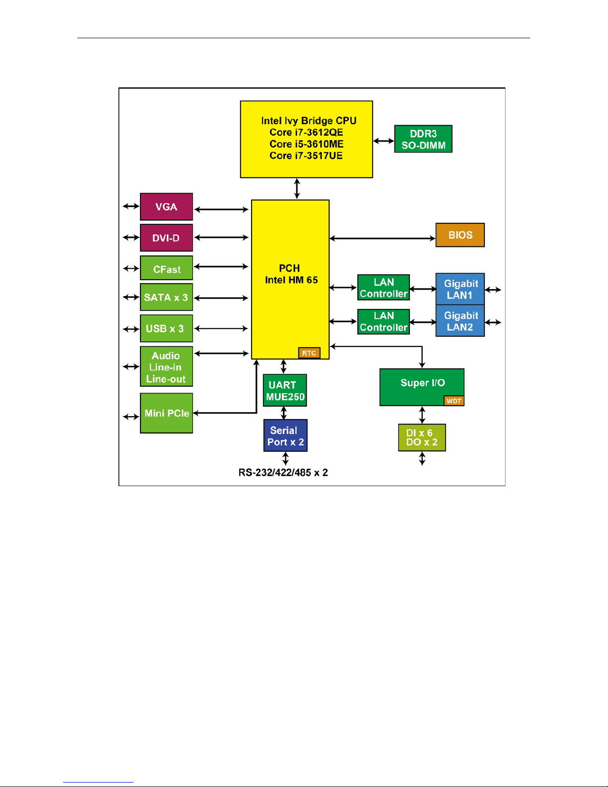
The V2616A series of embedded comput ers are based on the Intel Core i5/i7 processor, and feature 2
RS-232/422/ 485 seri al ports, dual Gigabit Ethernet ports, 3 USB 2.0 ports, and dual VGA/DVI-D video output.
V2616A computers have essential compliance with EN 50155, making them ideal for railway and o ther
industrial transport applications. V2616A computers come with a CFast socket that provides ample and secure
data buffering or additional storage expansion, as well as 2 hot-swappable storage trays that accept 2.5" solid
state or hard disk storage drives, and may be arranged in software RAID 1 arrays to give full data redundancy.
Package Checklist
Each model ships with the following items:
• V2616A embedded c omputer
• 2 storage tray keys
• Power cable (CBL-M12FF5PPJ21-BK-15-IP68)
• Documentation and software CD or DVD
• Quick installation guide (printed )
• Warranty card
• 2 5-pin terminal blocks
NOTE: Please notify yo ur sales representative if any of the above items are missing or damaged.
Product Features
V2616A embedded computers have the following features:
• Compliant with EN 50121-4
• Essential compliance with EN 50155*
• IEC 61373 certified for shock and vibration resistance
• Two hot-swappable SATA storage trays for 2.5” SSDs or HDDs
• 24 to 110 VDC wide range isolated power input
• Easy battery replacement
• Smart Recovery for manual or automatic system recovery
• SynMap for system health monitoring
* Moxa defines “essential compliance” to inc lud e tho s e EN 50155 req uirem e nts that make prod uc ts more
suitable for rolling stock railway applic a tio ns .
Hardware Specifications
Computer
CPU:
• Intel® Core™ i5
-3610ME dual-core pr o cessor (3M Cache, 2.7 GHz) for V2616A-C5 series
•
Intel® Core™ i7-3517UE dual-core processor (4M Cache, 1.7 GHz) for V2616A-C7-T series
• Intel® Core™ i7
-3612QE quad-core processor (6M Cache, 2.1 GHz) for V2616A-C8 series
OS (pre
-installed): Linux or Windows Embedded Standard 7
System Chipset:
Mobile Intel HM65 Express Chipset
System Memory:
16 GB capacity, 4 GB pre-installed: 2 slot of 8 GB DDR3-1600 SO-DIMM SDRAM
USB:
3 USB 2.0 compliant hosts; 2 with type A connectors supporting system bootup, 1 with M12 conne c tor
Storage
Built
-in: 8 GB CFast to store OS
Storage Expansio n:
2 hot-swappable st orage trays for 2.5” SATA SSD or H DD
HDD Support:
1 internal SATA-II storage connector for 2.5” SSD or HDD
Page 6

V2616A Hardware Manual Introduction
1-3
Expansion Slot:
1 full
-size/half-size mini PCIe socket with 1 SIM card socket. Mini PCIe socket supports power on/off control
Other Peripherals
Audio:
Line-in, line-out (M12 X-coded)
Display
Graphics Controller:
Intel® HD Graphics 4000 (integrated)
VGA Interface:
DB15 female connector, max. resolution 2048 x 1536
DVI Interface:
DVI-D connector (Chrontel CH7307 SDVO to DVI transmitter ), max. resol utio n 19 20 x 1200
Ethernet Interface
LAN:
2 auto-sensing 10/100/1000 Mbps ports (M12 X-coded)
Serial Interface
Serial Standards:
2 software-selectable RS-232/422/485 ports (DB9 male)
Isolation Protec tion:
1.5 kV
ESD Prot ection:
4 kV for all signals
Serial Signals
RS
-232: TxD, RxD, DTR, DSR, RTS, CTS, DCD, GND
RS
-422: TxDA(-), TxDB(+), RxDB(+), RxDA(-), GND
RS
-485-4w: TxDA(-), TxDB(+), RxDB(+), RxDA(-), GND
RS
-485-2w: DataA(-), DataB(+), GND
Serial Communication Para me ters
Data Bits:
5, 6, 7, 8
Stop Bits:
1, 1.5, 2
Parity:
None, Even, Odd, Space, Mark
Flow Control:
RTS/CTS, XON/XOFF, ADDC® (automatic data direction control) for RS-485
Baudrate:
50 bps to 921.6 Kbps (non-standard baudrates supported; see user’s manual for details)
Digital Input
Input Channels:
6, source type
Input Voltage:
0 to 30 VDC at 25 Hz
Digital Input Levels for Dry Contacts:
• Logic level 0: Close to GND
• Logic level 1: Open
Digital Input Levels for Wet Contacts:
• Logic level 0: +3 V max.
• Logic level 1: +10 V to +30 V (Source to DI)
Isolation
Protection: 3 kV
Digital Output
Output Channels:
2, sink type
Output Current:
Max. 200 mA per channel
On
-state Voltage: 24 VDC nominal, open collector to 30 VDC
Connector Type:
10-pin screw terminal block (6 DI points, 2 DO points, DI Source, GND)
Isolation:
3 kV optical isolation
LEDs
System:
1 Power, 1 Sto ra ge
LAN:
2 100M/Link, 2 1000M/Link
Serial:
2 TX, 2 RX
Physical Characteristics
Housing:
Aluminum
Weight:
5 kg
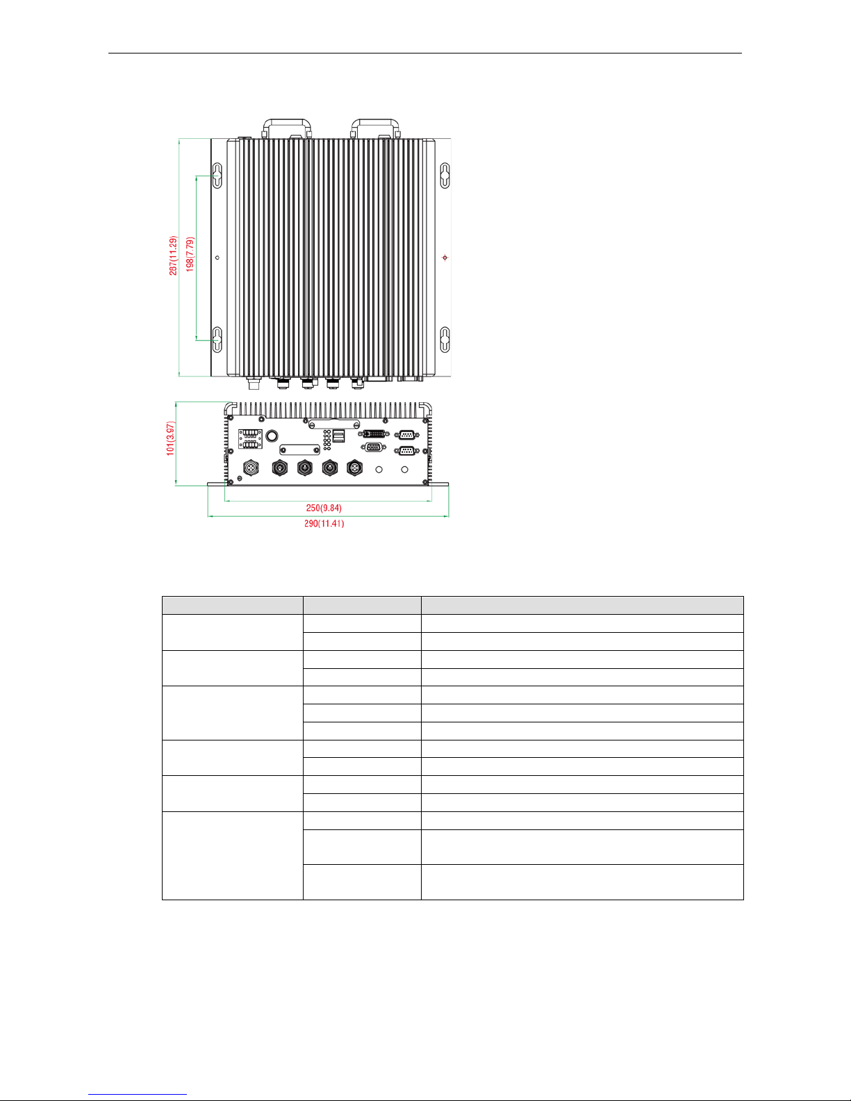
Dimensions
(with mounting ear): 287 x 290 x 101 mm (11.29 x 11.41 x 3.97 in)
Mounting:
wall
Environmental Limits
Page 7

V2616A Hardware Manual Introduction
1-4
Operating Temperature:
(without HDD installed)
Standard models:
-25 to 55°C (-13 to 131°F)
Wide temp. models:
-40 to 70°C (-40 to 158°F)
Storage Temperature:
(with SSD installed) -40 to 85°C (-40 to 185°F)
Ambient
Relative Humidity: 5 to 95% (non-condensing)
Anti
-vibration: EN 50155 standard
Anti
-shock: EN 50155 standard
Power Requiremen t s
Input Voltage:
24 to 110 VDC, M12 connector
Note: 24 and 110 VDC are EN 50155 compliant
Power
Requirements:
• 60 W (no
SSD/HDD attached)
• 2.5 A @ 24 VDC to 0.55 A @ 110 VDC (no SSD/HDD attached)
Power Button:
On/off (rear panel)
Standards and Cer tifications
Safety:
UL 60950-1, CSA C22.2 No. 60950-1-07, EN 60950-1
EMC:
EN 55022 Class A, EN 61000-3-2 Class D, EN 61000-3-3, EN 55024, FCC Part 15 Subpart B Class A
Rail Traffic:
EN 50155 (essential compliance*), EN 50121-3-2, EN 50121-4, IEC 61373
Green Product:
RoHS, CRoHS, WEEE
*Please contact Moxa or a Moxa
distributor for details.
Reliability
Automatic Reboot Trigge r:
Built-in WDT (watchdog timer) supporting 1-
255 second system reset, softwa re
programmable
Warranty
Warranty Period:
3 years
Details:
See www.moxa.com/warranty
Note: These hardware
specifications describe the embedded compute r unit itse lf, but not its official
accessories. In particular, the wide tempera tur e spec i f ic a tion d oes not apply to acc ess or ies s uc h as power
adapters and cables.
Page 8
V2616A Hardware Manual Introduction
1-5
Hardware Block Diagram
Page 9

2
2. Hardware Introduction
V2616A embedded computers are comp act and built rugged for use in industrial appl ic ations. LED indicators
help you monitor performance and identify trouble spots, multiple serial ports allow you to connect a variety of
devices for wireless operation, and the reliable and stable hardware platform lets you devote your attention to
developing your applications, rather than did d l ing with low -level APIs and device drivers.
The following topics are covered in this chapter :
Appearance
Dimensions
LED Indicators
Real Time Clock
Page 10
V2616A Hardware Manual Hardware Introduction
2-2
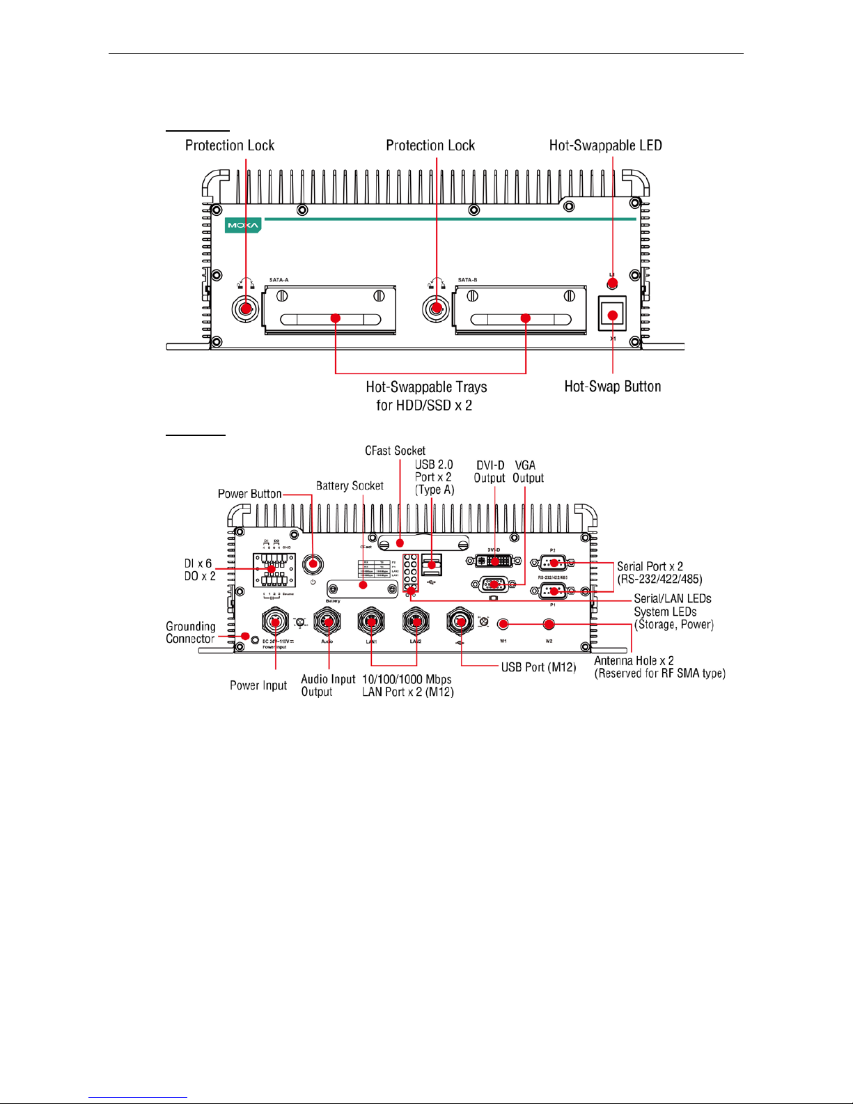
Appearance
Front View
Rear View
Page 11
V2616A Hardware Manual Hardware Introduction
2-3
Dimensions
LED Indicators
LED Name LED Color LED Function
Power Green Power is on and functioning normally
Off Power is off, or has failed
Storage Yellow CFast card/HDD/S SD is transmitting data.
Off CFast card/HDD/SSD is not transmitting data.
LAN (1, 2) Green 100 Mbps Ethernet mode
Yellow 1000 Mbps Ethernet mode
Off
10 Mbps or no activity
Tx (P1-P2) Green Serial ports P1-P2 transmitting data
Off Serial ports P1-P2 not transm itting d ata
Rx (P1-P2) Yellow Serial ports P1-P2 receiving data
Off Serial ports P1-P2 not receiving d a ta
L1 Red Programmable. By default, two disks rea d y to be removed.
Blinking Programmable. By default, disks inserted into incorrect
storage tray.
Off Programmable. By default, two disks inserted into correct
storage trays.
Page 12
V2616A Hardware Manual Hardware Introduction
2-4
Real Time Clock
The embedded computer’s real-time clock is powered by a lithium battery. We strongly recommend that yo u
NOT replace the lithium battery on your own. If the battery needs to be changed, contact the Moxa RMA service
team.
ATTENTION
There is a risk of explosion if the wrong type of battery is used. To avoid this potential danger, always be sure
to use the
correct type of battery. Contact the Moxa RMA service team if you need to replace your battery.
Caution
Dispose of used batteries
in a suitable manner. Consult the manufacturer of your battery for more details.
Page 13

3
3. Hardware Connection Description
In this chapter, we show how to connect the embedded computers to the network and to a variety of common
devices.
The following topics are covered in this chapter:
Installing the V261 6A
Wiring Requirements
Connecting the Power
Grounding the Unit
Connecting Data Transmission Cables
Connecting to the Network
Connecting to a Serial Device
Installing a CFast Card
Connecting an Audio Input
Digital Input/Output
Connecting to a VGA Moni t o r
Connecting to a DVI-D Monitor
Connecting to USB Ports
Installing an Intern al S to r age De vic e
Making a Stor age Drive Hot-Swappable
Upgrading the Memory Module
Installing the Mini PCIe Module
Page 14

V2616A Hardware Manual Hardware Connection Description
3-2
Installing the V2616A
Wall or Cabinet Mounting
The V2616A comes with two wall-mounting brackets. Use two screws per side to attach the V2616A to a wall
or cabinet.
Wiring Requirements
This section describes how to connect peripheral devices to the embedded computer.
You should read and follow these common safety precautions before proceeding with the ins talla tio n of any
electronic device:
• Use separate paths to route wiring for power and devices. If power wiring and device wiring paths must
cross, make sure the wires are perpendicular at the intersectio n po int.
ATTENTION
Do not run signal or communication wiring together with power w iring in the sam e wire
conduit. To avoid
interference, wires with different signa l c haracteristics should be routed separately.
• Use the type of signal transmitted through a wire to determine which wires should be kept separ ate . The
rule of thumb is that wiring that shares similar electrical characteristics can be bundled together.
• Keep input wiring and output wiring separate.
• It is advisable to label the wiring to all devices in the system.
ATTENTION
Safety First!
Be sure to disconnect the power cord before installing and/or wir ing your
V2616A.
Wiring Caution!
Calculate the maximum possible current in each power wir e and com mon wire . Observe all elec trical codes
dictating the maximum current allowable for e ac h wire
size.
If the current goes above the maximum ratings, the wiring could overheat, causing serious damage to your
equipment.
Temperature Caution!
Be careful when handling the unit. When the unit is plugged in, the internal components generate heat, and
conseq
uently the outer casing may feel hot to the touch.
Page 15
V2616A Hardware Manual Hardware Connection Description
3-3
Connecting the Power
Connect the 24 to 110 VDC power line with M12 conne c tor to the V2616A computer. If the power is supplied
properly, the Ready LED will glow a solid green after a 25 to 30 second delay.
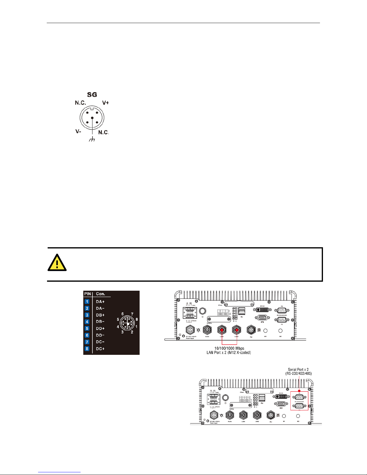
Grounding the Unit
SG:
The Shielde d Ground (sometimes called Protected Ground
) contact is the central pin
of the power input connector. Connect the SG wire to an appropriate
ly grounded metal
surface.
Connecting Data Transmission Cables
This section describes how to connect V2616A embedded computers to a network and serial devices.
Connecting to the Network
Plug your network cable into the computer’s Ethernet port. The other end of the cable should be plugged into
your Ethernet network. When the cable is properly connected, the LEDs on the embedded computer’s Ethernet
port will glow to indicate a valid connection.
Two 10/100/1000 Mbps Ethernet ports using M12 X-coded connectors are located on the rear panel. See the
figures below for the location of the Ethernet ports and the pin assignments.
ATTENTION
This is the pin assignment
for the computer-side ports on the V2616A shell.
When wiring the switch side of a
third
-party Ethernet cable, you will need to mirror the pin assignment.
Connecting to a Serial Device
Use a serial cable to plug your serial device into the
embedded comput er’s serial port. Serial ports P1
to P2 have male DB9 connectors and can be
configured for RS-232, RS-422, or RS-485 using
software. The pin assignments are shown in the
table at the top of the next page.
Page 16
V2616A Hardware Manual Hardware Connection Description
3-4
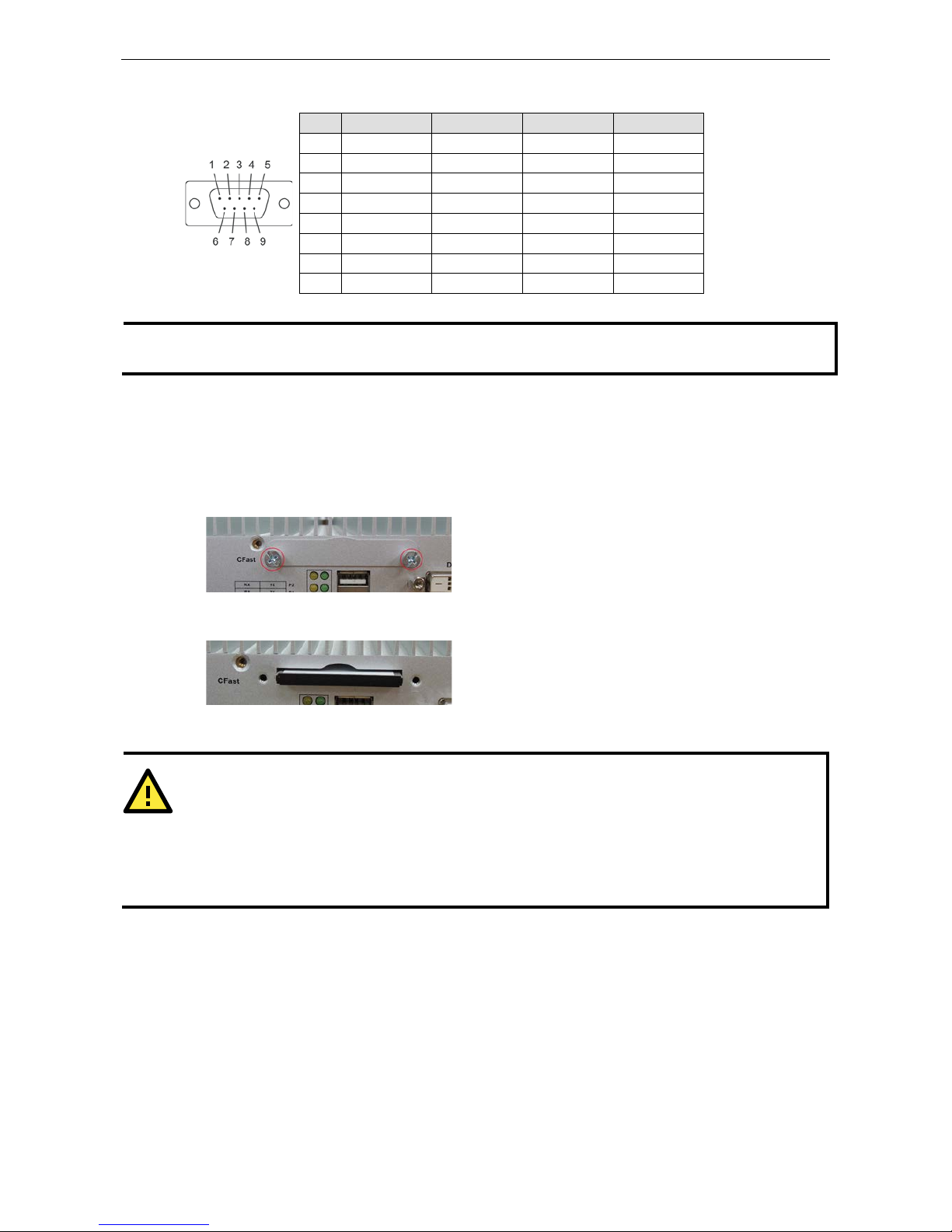
DB9 Male Port RS-232/422/485 Pinouts
Pin RS-232 RS-422 RS-485-4W RS-485-2W
1 DCD TxDA(-) TxDA(-) –
2 RxD TxDB(+) TxDB(+) –
3 TxD RxDB(+) RxDB(+) DataB(+)
4 DTR RxDA(-) RxDA(-) DataA(-)
5 GND GND GND GND
6 DSR – – –
7 RTS – – –
8 CTS – – –
NOTE
This is the pin assignment for the computer-side connectors on the V2616A shell. If you are wiring
peripheral
-side connectors for a serial cable, you will need to mirror the pin assignm e nt.
Installing a CFast Card
The V2616A embedded computers come with a CFast card socket. To install a card, follow these instructions:
1. Disconnect the V2616A from its power source.
2. The CFast socket is located on the center of the rear panel. Unscrew the CFast socket cover.
3. Insert the CFast card into the socket. Make sure you insert it in the correct direction. When finished, fasten
the socket cover with screws.
4. If you need to remove the CFast card, simply push the card inward to activate the spring-locking
mechanism, and gently r emove it once it pops out.
ATTENTION
The
V2616A embedded computer does not support the CFast hot swap and PnP (Plug and Play) functions.
Please remember y
ou must cut power first, before inserting or removing the CFast card.
In addition,
please note that the operating system of the V2616A (Linux or Windows Embedded Standard 7
)
is
stored on the CFast card, so if you change out the card you will need to re-install the operating system.
For
details on how to automate this, r
efer to the System Recovery section of the V2616A software manual.
Page 17
V2616A Hardware Manual Hardware Connection Description
3-5
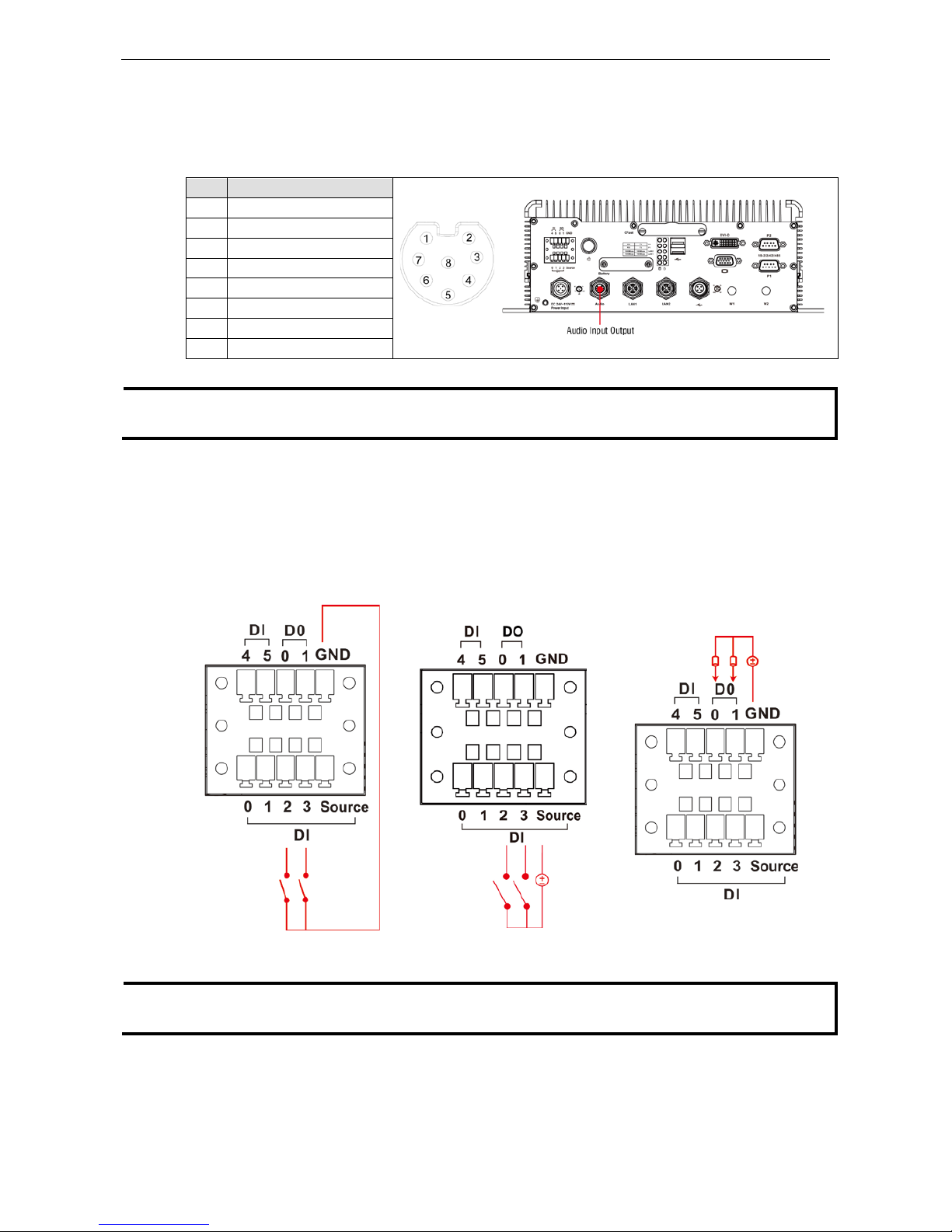
Connecting an Audio Input
The V2616A comes with an M12 X-coded audio input/output connector, allowing users to connect a speaker or
an earphone.
Pin Audio
1
Line-in, right
2 GND
3 Line in plug-in detected
4 Line-in, left
5 Line-out, left
6 Line out, plug-in detected
7 Line-out, right
8 GND
NOTE
This is the pin assignment for the computer-side connectors on the V2616A shell. If you are wiring
peripheral
-side connectors for an audio cable, you will need to mirror the pin assignment.
Digital Input/Output
The V2616A comes with a 6-ch digital input and a 2-ch digital output through a terminal block connector. The
pin assignments and the wiring methods are shown below.
DI Wiring: Dry Contact DI Wiring: Wet Contact DO Wiring: Dry Contact
NOTE
If
you are using wet contacts, you must connect source to power. In addition, both DI and DO can only be
wired as
sink types
Page 18
V2616A Hardware Manual Hardware Connection Description
3-6
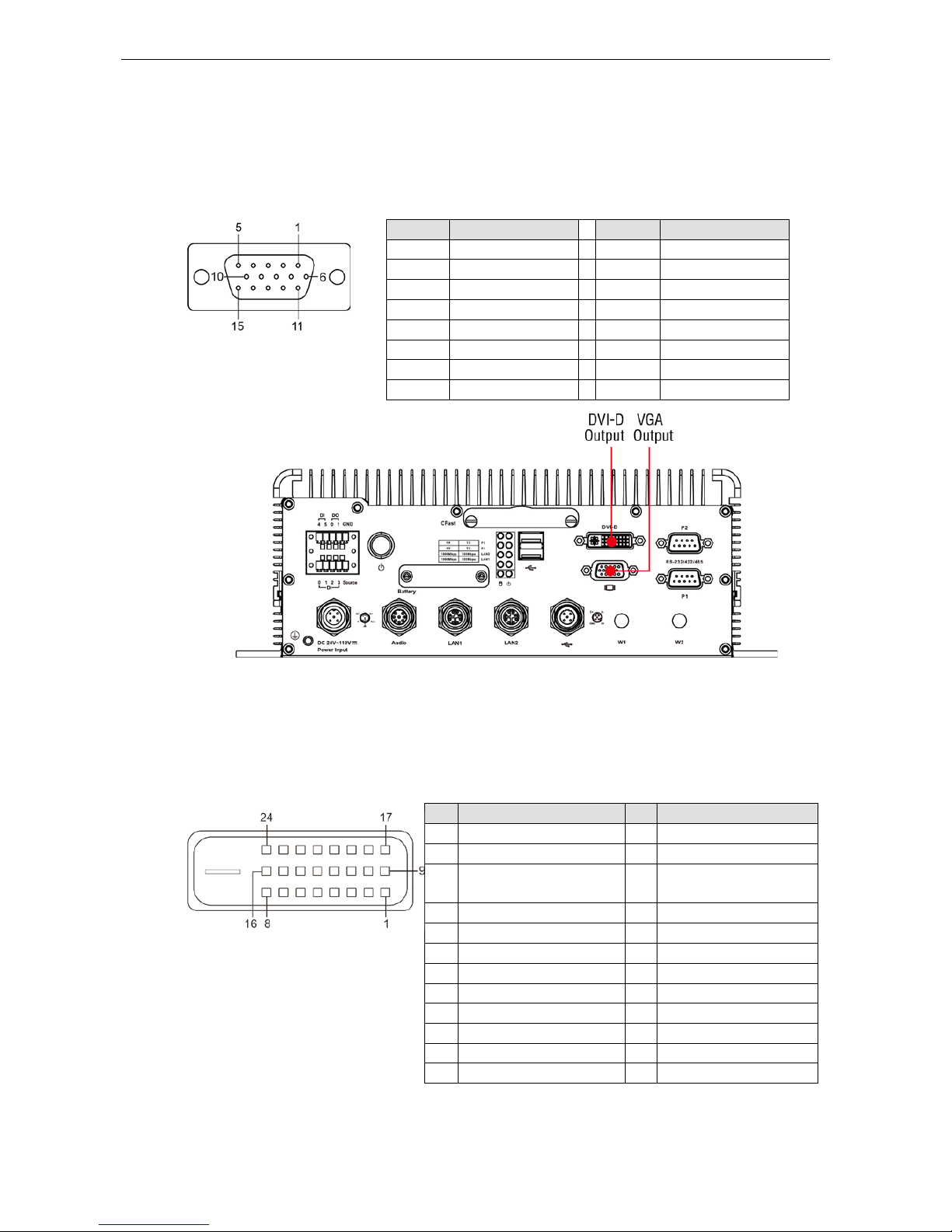
Connecting to a VGA Monitor
The V2616A comes with a D-Sub 15-pin female connector on the front panel to connect a VGA monitor . To
ensure that the monitor image remains clear, be sure to tighten the monitor cable afte r conne c ting it to the
V2616A. The location and the pin assignments of the video outputs are shown in the diagram below.
DB15 Female Connector
Pin No. Signal Definit ion Pin No. Signal Definition
1 Red 9 VCC
2 Green 10 GND
3 Blue 11 NC
4 NC 12 DDC2B Data
5 GND 13 HSYNC
6 GND 14 VSYNC
7 GND 15 DDC2B Clock
8 GND
Connecting to a DVI-D Monitor
The V2616A computer also comes with a DVI-D output for DVI video. Use the cable to connect the DVI-D output
to the monitor; if you must rewire a cable, refer to the following table for pin assignm e nts.
DVI-D Connector
Pin Signal Definition Pin Signal Definition
1 T.M.D.S. Data2- 13 N/C
2 T.M.D.S. Data2+ 14 +5V Power
3 T.M.D.S. Data2 Shield 15 Ground (return for +5V,
HSync, and VSync)
4 N/C 16 Hot Plug Detect
5 N/C 17 T.M.D.S. Data06 DDC Clock 18 T.M.D.S. Data0+
7 DDC Data 19 T.M.D.S. Data0 Shield
8 N/C 20 N/C
9 T.M.D.S. Data1- 21 N/C
10 T.M.D.S. Data1+ 22 T.M.D.S. Clock Shield
11 T.M.D.S. Data1 Shield 23 T.M.D.S. Clock+
12 N/C 24 T.M.D.S. C lo ck -
Page 19

V2616A Hardware Manual Hardware Connection Description
3-7
Connecting to the USB P or ts
On its rear panel the V2616A has an X-coded M12 USB 2.0 port, as well as 2 type A USB 2.0 ports. The hosts
can be used for an external flash disk or hard drive for storing large amounts of data. You can also use these
USB hosts to connect to a keyboard or a mouse. See the following figures for the locations of the USB ports and
the M12 X-coded connector p in assig nm e nt.
Pin USB
1 D+
2 D3 +5V
4 GND
5 N.C.
NOTE
This is the pin assignment for the computer-si de USB por ts on the V2616A shell. If you are wiring
peripheral
-side connectors for a USB cable, you will need to mirror the pin assignment.
Installing an Internal Storage Device
The V2616A computer comes with an internal storage tray that allows users to install a 2.5-inch SATA storage
device, such as a hard disk or a SSD drive. Take the following steps to install your storage device.
1. Remove the 6 screws from the V2616A’s rear panel.
2. Install the hard disk o nto the interna l s to rage kit. Connect the cable and connector.
Page 20
V2616A Hardware Manual Hardware Connection Description
3-8
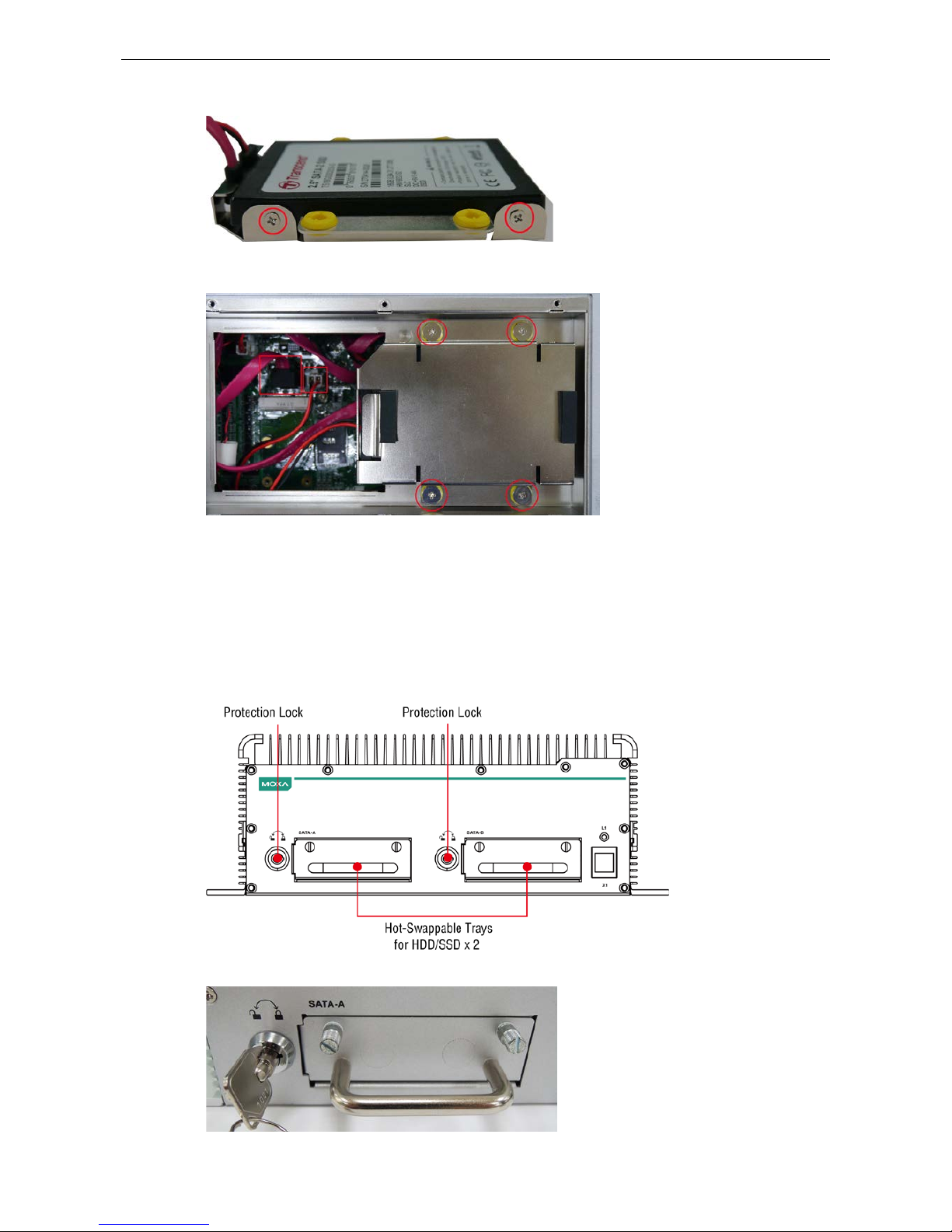
3. Fasten the two screws o n each side of the hard d isk (total of four).
4. Install the storage kit into the V2616A computer. Fasten four screws on the kit, and connect the cable the
power onto the V2616A ’s main board.
5. Replace the cover onto the back of the computer.
Making a Storage Drive Hot-Swappable
V2616A computers come with 2 faceplates over the storage drive trays; users may attach storage drives to the
faceplates to install additional s tor age media, such as hard disks (HDD) or solid-state drives (SSD). The
following section gives instructions for installing the storage d evic e s i n to the hot-swap trays.
1. The two faceplates on the front panel of the V2616A may be locked, for extra storage secur ity .
2. Rotate the ke y counterclockwise to unlock the protection lock.
Page 21
V2616A Hardware Manual Hardware Connection Description
3-9
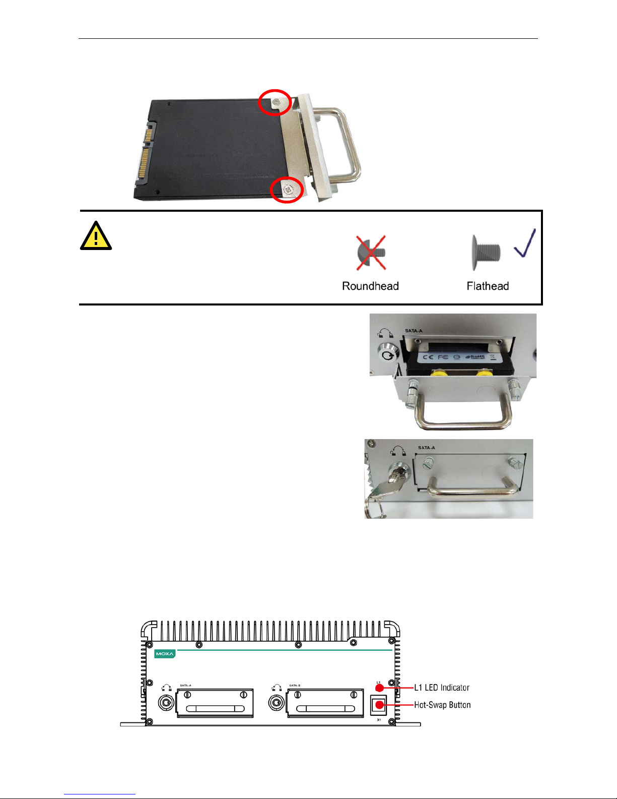
3. Pull out the faceplate by unscrewing the thumbscrews in the upper corners, and then remove the plate.
Fasten the storage drive to the faceplate flange as shown below, using the two flathead screws that were
shipped with your V2616A.
ATTENTION
To
successfully fit the disk into the slot, use the
flathead
screws to fasten the hard disk to the tray.
Do not
use the roundhead screws, since they may
prevent you from being able to
insert the t ray into the
slot.
4. Carefully align the drive with the drive slot, and gently insert
the drive into the computer, taking care that it slides
smoothly and firmly into the SATA mounts.
5. When finished, turn the key c lockw is e to activate the lock
and tighten the thumbscrews. Use the same method to
install a hard disk in second storage tray.
As these are hot-swappable storage trays, you can replace the storage disks while the computer is still powered
on. Follow these steps:
1. Push the hot-swap button, located on the lower right of the front panel.
2. Observe the L1 LED indicator (marked in the diagram below). When the LED starts blinking, the system will
start to unmount the storage disk.
3. When the LED stops blinking, you may remove the storage drive.
Page 22

V2616A Hardware Manual Hardware Connection Description
3-10
Upgrading the Memory Module
V2616A embedded c omputers come with two 200-pin, DDR3-1600 SODIMM m emory slots that can provide up
to 16 GB of memory. One 4 GB memory module is installed at the factory. To upgrade a memory module, follow
these instructions:
1. Disconnect the V2616A from the power source.
2. Remove the 21 screws that secure the back panel to the case. See the following figure for details.
3. Pull up the back cover of the computer; you will now
see the memory sockets on the main board.
4. Carefully remove the module by pushing the latches
on both sides of the module, freeing it to be
removed.
5. After removing the memory card , ins ta ll the new
module by gently but firmly inserting it into the RAM
slot. Before securing the card in place, be sure you
have aligned the indentations on each sid e of the
card with the mechanical locks that will hold it in
place (shown at right, in the red circles).
Once the card is properly aligned, gently push the
card down, until it locks in place. You should hear an
audible click; before continuing, make sure the
latches are firmly in place.
6. When finished, replac e the b ack cover of the V2616A computer.
Page 23

V2616A Hardware Manual Hardware Connection Description
3-11
Installing the Mini PCIe Module
The V2616A computer comes with a mini PCIe socket, allowing users to insta ll a mini PCIe module like those
used for cellular communications. Follow these steps to installation a module.
1. Pull up the back cover of the computer; you will be able to see the mini PCIe socket on the main board.
2. Install the module into the socket. Fasten two screws on one end of the module. In addition, pull up the SIM
card holder beside the socket.
3. Insert the SIM card in the holder by first dropping the holder into place (flush with the board), and then
locking it down by sliding it into p lac e .
Page 24

V2616A Hardware Manual Hardware Connection Description
3-12
4. Connect the cellular ante nna cable to the module.
5. Pass the connector of the antenna cable through the antenna hole on the rear panel of the computer. You
may use either the W1 or W2 hole. Pass the locking washer over the outer end of the connector first, and
then fasten the nut to lock the connector against the face of the computer.
NOTE
The cellular module, cable, connector, and antenna are not include d in the product package, and must be
purchased
separately.
Page 25

4
4. BIOS Setup
This chapter describes the BIOS settings of the V2616A computer. The BIOS is a set of input/output control
routines for peripherals. The BIOS is used to initializ e b as ic p eripherals and helps boot the operating system
before the operating system is loaded. The BIOS setup allows the user to modify the system configurations of
these basic input/output peripherals. All of the configurations will be stored in the battery backed up CMOS RAM,
which retains the system information after sy s te m reboo ts or the power is remov ed.
The following topics are covered in this chapter :
Entering the BIOS Setup
Main Information
Advanced Setting s
Bo ot Configuration
HD C Conf iguration
Video Configuration
Chipset Configuration
PCI Expres s Co nfig uration
Har d ware Monitor
Smart Recovery Info
Security Settings
Se t S upervisor Password
Power Settings
Turbo Mode
Auto Wake on S5
Wake on LAN
Boot Settings
Boot Type
PXE B oo t to LAN
Add Boot Options
USB Boot
EFI Device First
Boot Delay Time
Legacy
Exit Settings
Ex it S aving Changes
Save Change Without Exit
Ex it D is c arding Changes
Load Optimal Defaults
Load Custom Defaults
Save Custom Defaults
Discard Changes
Upgrading the BIOS
Page 26
V2616A Hardware Manual BIOS Setup
4-2
Entering the BIOS Set up
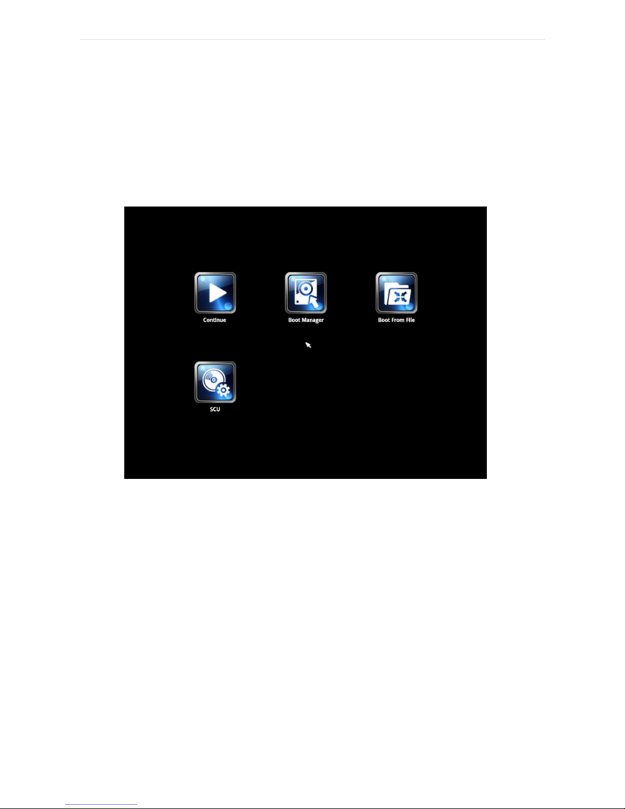
To enter the BIOS setup utility, press the F2 key while the system is booting up. The main BIOS Setup screen
will appear. Four options will be available.
Continue: Continue to boot up
Boot Manager: Select the device for booting up
Boot From File: Select the UEFI boot up file
SCU: Enter the BIOS configuration step.
Select SCU to enter the BIOS configuration.
When you enter SCU, a basic description of each functio n key is liste d at the bo ttom of the screen. Refer to
these descriptions to learn how to use them.
F1: General Help
F5/F6: Chang e Values
F9: Setup Defaults
F10: Save and Exit
↑↓
: Select Item
← →
: Select Menu
ESC: Exit
ENTER: Select or go to Sub me nu.
Page 27
V2616A Hardware Manual BIOS Setup
4-3
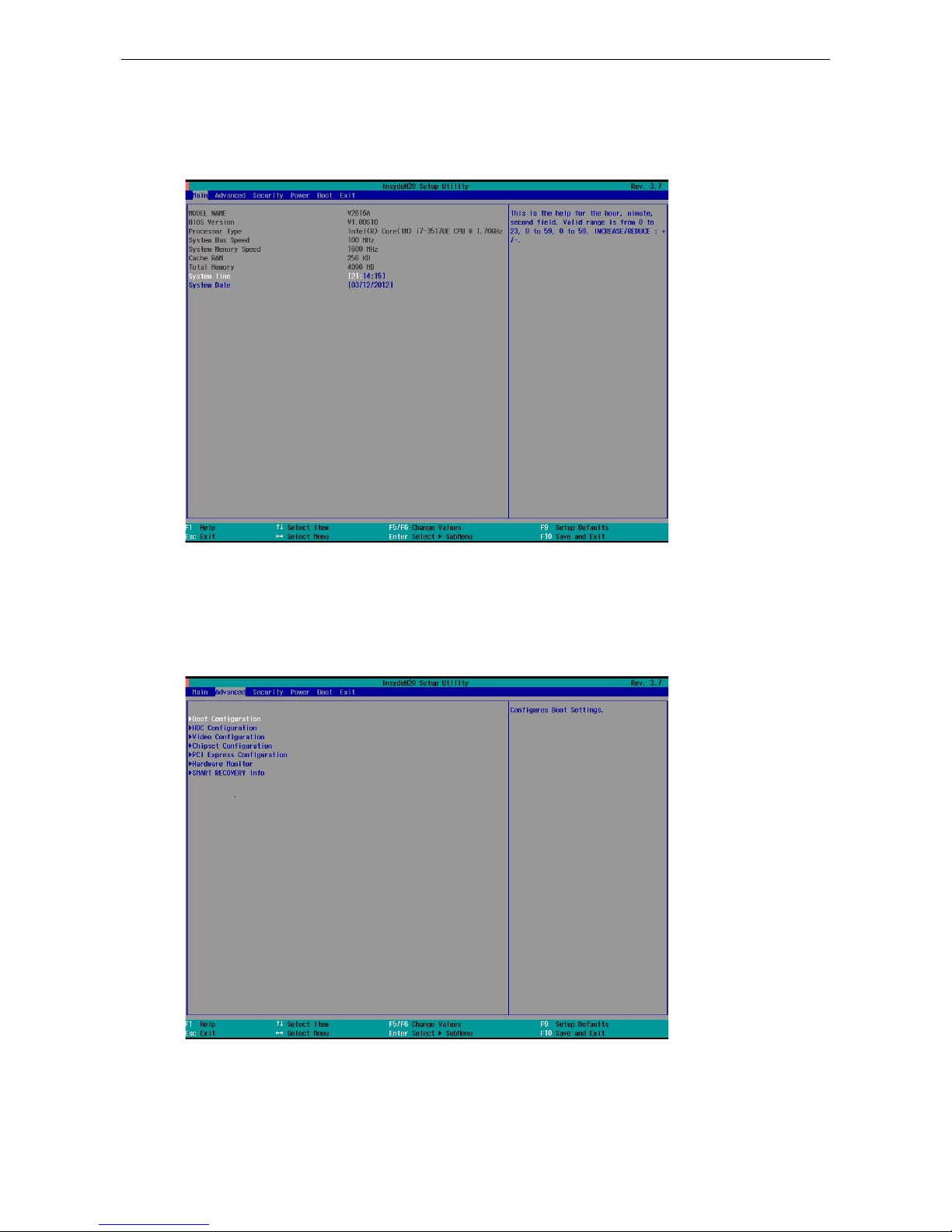
Main Information
The main page indicates the system information, such as model name, BIOS version, and CPU type. Users may
view the basic system hardware information in the page.
Note: the information for Processor Type will vary depending on the different models that you purchase.
Advanced Settings
The “Advanced Features” screen will appear when choos ing the “Advanced” item from the main menu.
Page 28

V2616A Hardware Manual BIOS Setup
4-4
Boot Configuration
This item allows users to configure the default value of Numloc k .
Option: On (default), Off.
HDC Configuration
The host drive controller may be configured for IDE or AHCI mode (default).
When the AHCI mode is selected, the following scree n will appe ar.
Page 29
V2616A Hardware Manual BIOS Setup
4-5
Serial ATA Port 0 to 4
This setting allows the user to display info rmati o n abo ut the installe d drives.
AHCI SALP
Note that AHCI SALP will only appear when AHCI mode is selected. This item allows you to enable aggressive
link power management (SALP) in AHCI. SALP enables the host bus adapter to conserve power by directly
detecting when a SATA drive is no longer processing infor matio n and the n immed ia te ly shifting it into
suspended or sleep modes without waiting for software processes to initiate power-down processes.
Host Capability Register bit 26.
Options: Enabled (default), Disabled
SATA Port 0 to 4 - HotPlug
This item allows you to enable/disable hotplug capabilities (the ability to remove the drive while the computer
is running) for installed storage drives.
Options: Disabled (default for Port 0), Enabled (default for Por t 1 to Port 4)
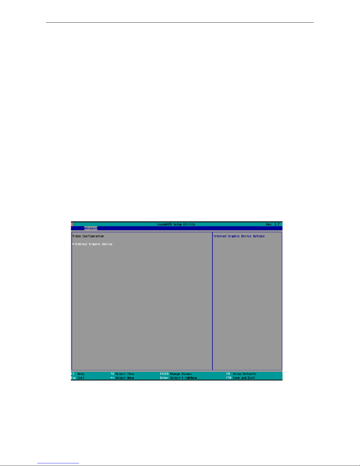
Video Configuration
This item allows you to configure the integrated graphic s devic e (IGD ) for things like memory allocation
(DVMT)
Page 30
V2616A Hardware Manual BIOS Setup
4-6
Internal Graphics Device
This option allows you to enable/disable the interna l gr ap hics device.
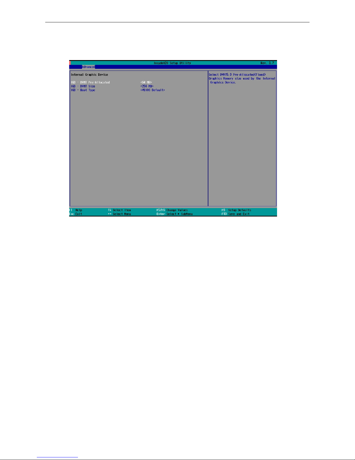
IGD—DVMT Pre-Allocated
This item allows you to configure pre-allocated memory capacity for the IGD. Pre-allocated graphics memory
is invisible to the operating system.
Options: 64 MB (default), 32 MB, 96 MB, 128 MB, 256 MB, 512 MB
DVMT is a BIOS solution where “the optimum amount of memory is dynamically allocated and de-allocated as
needed for balanced graphics and system performance , through I nte l® Dir e c t AGP and a highly effic i e nt
memory utilization scheme. DVMT ensures the most efficie nt us e of av ailable system memory resources for
maximum 2D/3D graphics performance.
IGD—DVMT Size
This item allows you to configure the maximum amount of memory DVMT will use when allocating additional
memory for the internal gr aphics dev ic e .
Options: 256 MB (default), 128 MB, M ax
IGD—Boot Type
This item allows you to select the video device activa te d during PO S T.
Options: VBIOS Default (default), VGA, DVI
Page 31
V2616A Hardware Manual BIOS Setup
4-7
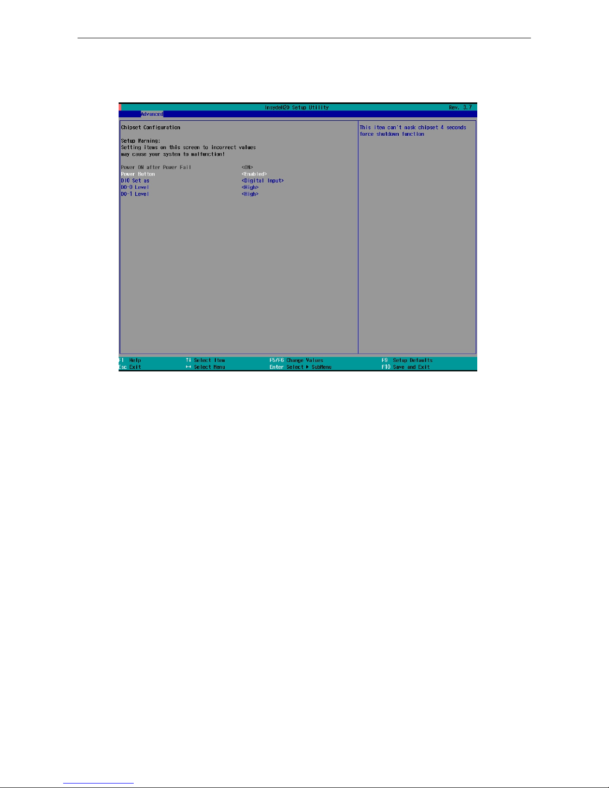
Chipset Configuration
This item allows you to configure the chipse t settings.
Power ON after Power Fail
This item allows you to enable the computer form automatically powering up after a system crash.
Options: ON (default)
Power Button
This item allows you to enable/disable the power button. If you enable the power button function, press the
power button to power on or power off the compute r . If you disab le the powe r b utto n function, you need to
press for more than four seconds to power off the computer.
Options: Enabled (default), Disab le d
DI0 Set as
This item allows you to set the DI0 as Digital Input or Reset.
Options: Digital Input (default), R e set#
DO-0 Level
This item allows you set the DO-0 as high or low status.
Options: High (default), Low
Page 32
V2616A Hardware Manual BIOS Setup
4-8
DO-1 Level
This item allows you set the DO-1 as high or low status.
Options: High (default), Low.
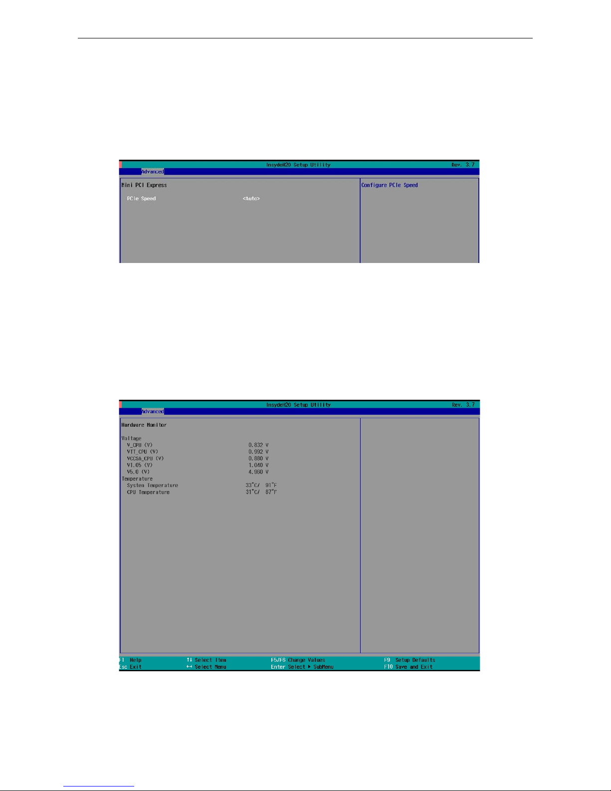
PCI Express Configuration
PCIe Speed
This item allows you to configure the speed of the mini PCIe inter f ace .
Option: Auto (default), Gen1, Gen2
Hardware Monitor
This item allows you to view stats like C PU and system temperature, voltage levels.
Note that the voltage values will vary depending on the different models, and there will be 5% tolerance for the
temperature values. However, this f unc tion works only when the ambient temperature is above 0°C.
Page 33

V2616A Hardware Manual BIOS Setup
4-9
Smart Recovery Info
This items allows you to view the Smart Recovery information.
Load Smart Recovery Default
This item allows you to load Smart Recovery default value. Refer to the Smart Recovery Website:
http://www.moxa.com/product/Smart-Recovery.htm
Options: Yes (default), No
Security Setti n g s
This section allows users to configure securi ty setting s with a supervisor password.
Page 34
V2616A Hardware Manual BIOS Setup
4-10
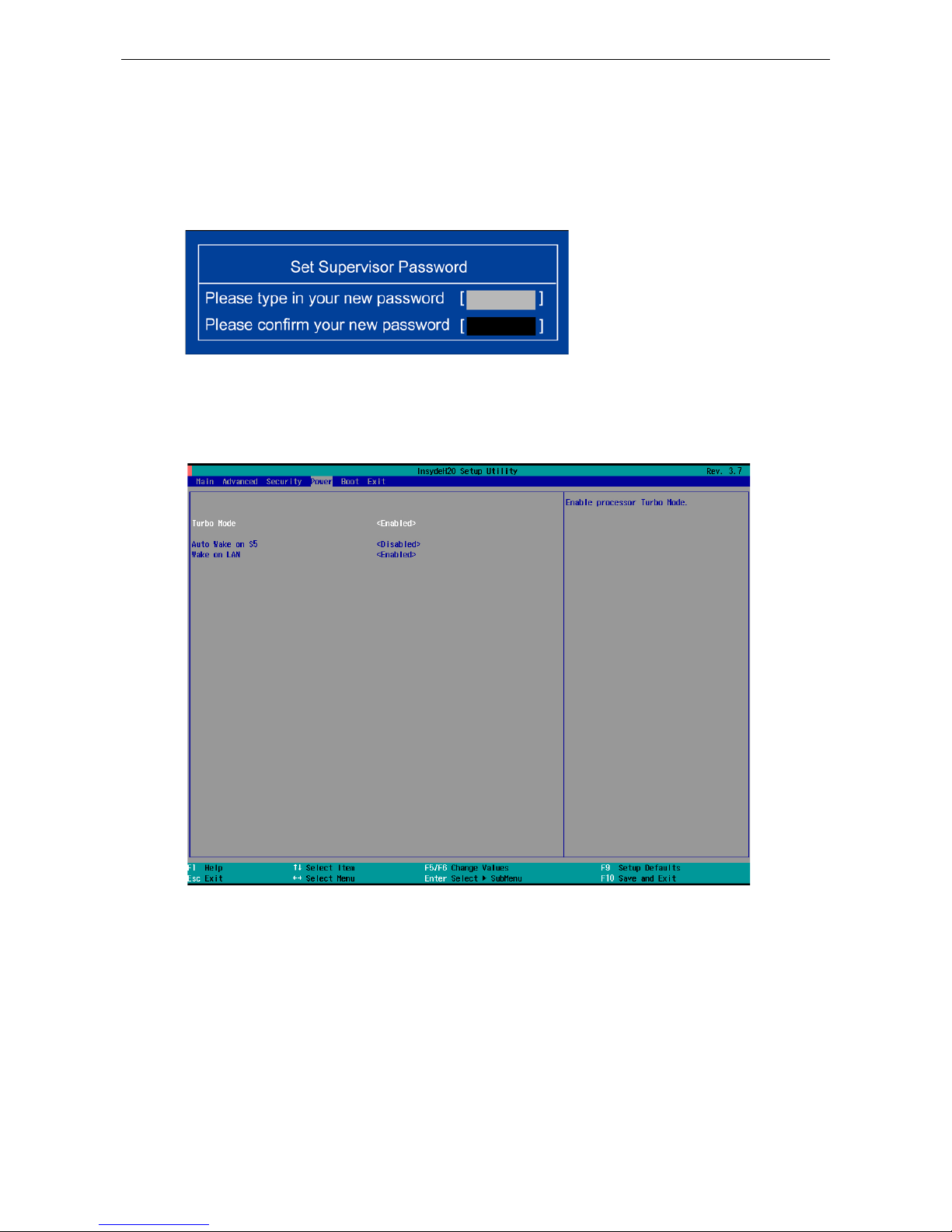
Set Supervisor Password
This item allows you set the supervisor password. Sele c t and then enter the p asswo rd , and then confirm the
password again.
To delete the password, enter Set Supervisor Password and then enter the old password; then, leave the
new password fields blank, and press enter.
Power Settings
The section allows users to configure power se tting s .
Turbo Mode
This item allows users to determine whether to enable the Intel CPU Turb o Boos t tec hnology.
Options: Enabled (default), Disable d.
Auto Wake on S5
This item allows you to configure the computer to wake from S5 status. S5 stands for Soft Off, where the PSU
remains engaged but power to all other parts of the system is cut. Auto-wake on S5 schedules a soft-reboot at
certain periodic times that may be specified in the BIOS.
Page 35

V2616A Hardware Manual BIOS Setup
4-11
Options: Disabled (default); By Every Day (user specif i e s a regul ar d aily time when the comp uter will pow e r
up); By Day of Month (user specified a regular day each month when the computer will po wer up )
Wake on LAN
This feature is used to wake on the system by a LAN device from a remote host.
Options: Enabled (default), Disable d.
Page 36

V2616A Hardware Manual BIOS Setup
4-12
Boot Settings
The section allows users to configure boo t setting s .
Boot Type
This item allows you to enable/disable quick boot function.
Options: Dual Boot Type (default), Legacy Boot Type, UEFI Boot Type.
PXE Boot to LAN
This item allows you to enable/disable PXE boot to LAN function.
Options: Disabled (default), Enab le d
Add Boot Options
This item allows you to add the boot order options for the new boot devices on and the removable devices, such
as USB disk.
Options: Last (default), First
USB Boot
This item allows you to enable/disable USB boot function..
Options: Enabled (default), Disab le d
Page 37

V2616A Hardware Manual BIOS Setup
4-13
EFI Device First
This item allows you to determine EFI device first or legacy device first. If enabled, EFI device will be the first;
if disabled, legacy device will be the first.
Options: Disabled (default), Enab le d
Boot Delay Time
This item allows you to configure the delay time value for users to input hot key during POST time.
Options: 0 Second (default), 3 Seconds, 5 Seconds, 10 Second s
Legacy
Normal Boot Menu
This item allows you to configure the boot menu.
Options: Normal (default), Advance
Boot Type Order
This item allows you to select the boot order. Use -/F5 (move dow n) or +/F6 (mov e up ) to change v alue s .
Options: Hard Disk Drive (default), CD/DVD-ROM Drive, USB, Others
Hard Disk Drive/USB Drive
This item allows you to view installed devices such a s hard disk drives, USB drives, or CD-ROMs. For example,
if you have inserted a USB drive into the computer, it will appear here. You can view and select boot order in
the same type storage.
Page 38

V2616A Hardware Manual BIOS Setup
4-14
Exit Settings
The section allows users to exit the BIOS environme nt.
Exit Saving Changes
This item allows you to exit the BIOS environme nt and save the v al ues you have just co nfig ur e d.
Options: Yes (default), No
Save Change Without Exit
This item allows you to save changes without exiting the BIOS environment.
Options: Yes (default), No
Exit Discarding Changes
This item allows you to exit without saving a ny changes that m ig ht have bee n made to the BIOS.
Options: Yes (default), No
Load Optimal Defaults
This item allows you to revert to the factory default BIOS values.
Options: Yes (default), No
Load Custom Defaults
This item allows you to load custom default values for the BIOS settings.
Options: Yes (default), No
Page 39
V2616A Hardware Manual BIOS Setup
4-15
Save Custom Defaults
This item allows you to save the current BIOS values as a “custom default” that may be reverted to at any time
by the “load custom defaults” selection just above.
Options: Yes (default), No
Discard Changes
This item allows you to discard all settings you have jus t configur ed .
Options: Yes (default), No
Upgrading the BIOS
This section describes how to upgrade the BIOS. However , Note that it is easy to per manently d a mage the
computer when upgrading the BIOS. We strongly recommend that you contact Moxa’s technical support staff
for assistance in order to obtain all necessary tools and the most current advice before attempting to upgrade
the BIOS on any Moxa device.
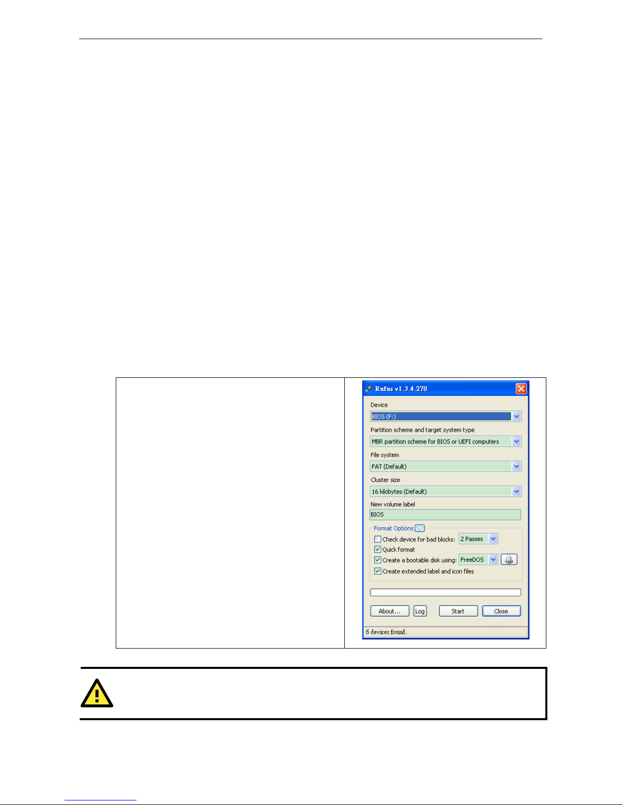
Step 1: Create a Boot ab l e USB Disk
Before upgrading the BIOS ev ery user should first c reate a bootable USB RAM drive as a system rescue devic e.
A useful software suite for building USB RAM drives may be found by searching for Rufus, which may then be
downloaded and used to create a bootable RAM drive. Do the following steps to create a bootable USB disk by
using Rufus.
1. Start the Rufus and in Device drop-down list select the
USB device that you want to use as a bootable disk.
2. Select MBR partition scheme for BIOS or UEFI
computers, let it can boot from legacy BIOS or UEFI.
3. Select FAT (Default) from File system drop-down
list.
4. Select 16 kilobytes (Default) for Cluster size.
5. Enter a drive name in New volume label.
6. Check Quick format, Create a bootable disk using
FreeDOS, and Create extended label and icon
files.
7. Click Start to format and create the bootable USB
drive.
ATTENTION
When you use the USB with
the capacity larger than 4 GB, you need to convert the file system type as FAT32.
Page 40

V2616A Hardware Manual BIOS Setup
4-16
Step 2: Prepare the Upgrade File
You must use the BIOS upgrade installation file to upgrade the BIOS. Contact Moxa’s technical department for
assistance.
1. Get the BIOS upgrade installation file. The file name should have following format: V2616AxxSx.exe (xx
refers to version numbers).
2. Copy the f il e to the Bootable USB Disk.
Step 3: Run the upgrade program on the V2616A Computer
1. Reboot the computer, pres s F2 while bo oting up to go to the Boot Manager
2. Select USB Disk as the first boo t source . Pre ss Ente r to co ntinue.
3. When boot up finishes, DOS screen will show up. Go to the directory where the upgrade file is located. For
example, if the upgrade file is stored in the V2616A folder, type cd V2616A.
C:\cd V2616A
4. Run the upgrade program by typing 2616A10S6.exe. Note that the upgrade filename may vary depending
on the versions.
C:\ V2616A>2616A10S6.exe
5. The upgrade program will be automatically performed. Wait until the procedure to be finished.
Page 41

V2616A Hardware Manual BIOS Setup
4-17
6. When the upgrade is finished, the computer will automatically reboot. You may check the BIOS version in
Main page of the BIOS Setup
ATTENTION
Do NOT switch off the power supply during the BIOS upgrade, since doing so may cause the system to crash.
Page 42

A
A. Regulatory Approval Statement
This device complies with part 15 of the FCC Rules. Operation is subject to the following
two conditions: (1) This device may not cause harmful inte rf e re nc e , and (2 ) this device
must accept any interference received, including inte rference that may cause undesired
operation.
Class A: FCC Warning! This equipment has been tested and found to comply with the limits for a Class A digital
device, pursuant to part 15 of the FCC Rules. These limits are designed to prov id e r e asonable prote c tion
against harmful interference when the equip m e nt is operated in a commercia l e nvir onment. This equipment
generates, uses, and can radiate radio frequency energy and, if not installed and used in accordance with the
instruction manual, may cause harmful interfere nc e to radio communic a tio ns . Operation of this equipment in
a residential area is likely to cause harmful interference in which case the user will be required to correct the
interference at his own expense.
European Community
Warning:
This is a class A product. In a domestic environment this product may cause r adio inter f er e nc e in whic h case
the user may be required to take adequate measures.
 Loading...