

Page 1
– 1 – – 2 – – 3 –
P/N: 1802026160010
V2616 Series
Quick Installation Guide
First Edition, August 2011
Overview
The V2616 Series EN 50155-certified embedded computers use
the Intel Core 2 Duo SP9300 x86 processor and feature 2
RS-232/422/485 serial ports, dual LAN ports, and 3 USB 2.0 hosts.
In addition, the V2616 computers provide VGA and DVI-D outputs,
and are EN 501 55 certified, making them robust enough for
railway and ind ustrial applicat ions.
Package Checklist
Before installin g the computers, verify that the package contains
the following it ems:
• V2616 embedded computer.
• Wall mounting kit
• PS2 to KB/MS Y-type cable
• Documentation and Software CD or DVD
• Quick installat ion guide (printe d)
• Product Warranty Statement (printed)
NOTE: Please notify your sales representative if any of the above
items are missing or damaged.
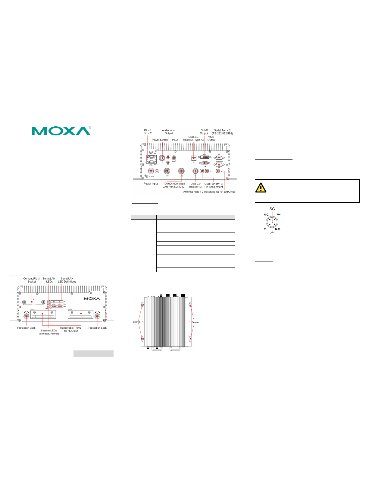
V2616 Panel Layout
V2616 Front & Rear Vie ws
LED Indicators
The following t able describes the LED indicator s located on the
front and rear pan els of the V2616.
LED Name
LED Color
LED Function
Power
Green
Power is on and functioning normally
Off
Power is off, or power error exists
Storage
Yellow
CF/HDD card is dete cted
Off
CF/HDD card is not detected
LAN (1, 2)
Green
100 Mbps Ethernet mode
Yellow
1000 Mbps Ethernet mode
Off
10 Mbps or no act ivity
Tx (P1-P2)
Green
Serial ports P1 -P2 transmitting data
Off
Serial ports P1-P2 not transmitting
data
Rx (P1-P2)
Yellow
Serial ports P1 -P2 receiving d ata
Off
Serial ports P1 -P2 not receiving data
Installing the V2616
The V2616 comes with two wall-mounting brackets. Use two
screws on each side to attach the V2616 to a wall or cabinet.
Connector Description
Power Connector
Connect the 24 VDC power line with M12 connectors to the V2616
computer. If the power is supplied properly, the Power LED will
light up. The OS is ready when the Ready LED glows a solid green.
Grounding the V2616
Grounding and wire routing help limit the effects of noise due to
electromagnetic interference (EMI). Run the ground connection
from the ground screw to the grounding surface prior to connecting
the power.
ATTEN
TION
This product is intended to be mounted to a well-grounded
mounting surface
, such as a metal panel.
SG: The Shielded Ground (sometimes called
Protected Ground) contact is the central pin
of the power input connector. Connect the
SG wire to an appropriate grounded metal
surface.
VGA and DVI Outputs
The V2616 comes with a D-Sub 15-pin female connector for a VGA
monitor; it also comes with a DVI-D connector for the DVI display.
These output interfaces are all located on the front panel. Use the
proper cable w hen connecting device s to the V26 16.
PS/2 Port
The V2616 embedded computer comes with a PS/2 mini-DIN
connector to connect to a PS/2 keyboard and PS/2 mouse. Use the
Y-type cable to convert the mini-DIN connector into two 6-pin
mini-DIN connectors to connect both a PS/2 keyboard and PS/2
mouse at the same time. You may also use the USB ports to
connect your USB-based keyboard and mouse. Note that without a
Y-type cable, the PS/2 connector on the V2616 can only work with
a PS/2 keyboard. A PS/2 mouse will not function when dire ctly
connected to the PS/2 connector on the V2616 embedded
computer.
CompactFlash Slot
The V2616 has a CompactFlash slot located on the front panel for
storing the operating system. It supports CF Type-I/II with DMA
mode. To install a CompactFlash card, remove the outer cover, and
then insert the CF card in the socket. When finished, push the
cover into the socket and fasten the screws.
Note that the operating system (Linux or Windows XP Embedded)
has already been stored on the CompactFlash card. If you change
the CompactFlash card, you will need to re-install t he V2616’s
Page 2
– 4 – – 5 – – 6 –
www.moxa.com/support
The Americas:
+1-714-528-6777 (toll-free: 1-888-669-2872)
Europe:
+49-89-3 70 03 99-0
Asia-Pacific:
+886-2-8919-1230
China:
+86-21-5258-9955 (toll-free: 800-820-5036)
2011 Moxa Inc., All Rig hts Reserve d
operating system. Refer to the System Recovery Section in the
Software User' s Manual for deta ils.
USB Hosts
The V2616 has one USB port with an M12 connector, and two USB
ports with type A connectors. All of the USB ports are located on
the rear panel. These USB ports can be used to connect flash disks
for storing large amounts of data.
Ethernet Ports
Two 10/100/1000 Mbps Ethernet ports using M12
connectors are lo
cated on the front panel. The pin
assignments
are shown in the following table .
10/100 Mbps
1000 MBps
1 – TRD3+
2 – TRD4+
3 – TRD4- 4 ERx-
TRD1-
5
ETx+
TRD2+
6
ERx+
TRD1+
7 – TRD3-
8
ETx-
TRD2-
Serial Ports
The serial ports use DB9 connectors. Each port can be configured
by software for RS-232, RS -422, or RS -485. The pin assignments
for the por ts are shown in the fo llowing table:
Pin
RS-232
RS-422
RS-485
(4-wire)
RS-485
(2-wire)
1
DCD
TxDA(-)
TxDA(-)
– 2 RxD
TxDB(+)
TxDB(+)
– 3 TxD
RxDB(+)
RxDB(+)
DataB(+)
4
DTR
RxDA(-)
RxDA(-)
DataA(-)
5
GND
GND
GND
GND 6 DSR – – – 7
RTS – – – 8
CTS – –
–
Audio Interface
The V2616 comes with an audio input and an audio output,
allowing users to connect a speaker or an earphone.
DI/DO
The V2
616 comes with a 6-
ch digital input and
2
-ch digital out put in the termin al block
connectors.
Removable Stor age Trays
The V2616 computers come with 2 removable slots for inserting
additional sto rage media. To insert the hard disk, simply remove
the screws from the tray disk, fasten the hard disk with the screws,
and then place the tray back in the slot. Protection keys are also
provided to protect the disk tray from being removed. Refer to the
Hardware User’s Manual for detailed storage installation
instructions.
Real-time Clock
The V2616’s real-time clock is powere d by a lithium bat tery. We
strongly recommend that you do not replace the lithium battery
without help from a qualified Moxa support engineer. If you need
to change the batte ry, contact the M oxa RMA service team.
ATTENTION
There is a risk of explosion if the battery is replaced by one
of incorrect type.
Powering on the V2616
To power on the V2616, connect the power cable to the V2616’s
M12 power connector located at the rear panel. Press the power
button to turn on the computer. Note that the Shielded Ground
wire should be connected to the central pin of the connector. It
takes about 30 seconds for the system to boot up. Once the system
is ready, the Po wer LED will light up.
Configuring the Ethernet Interface
Power on the V2616 computer after connecting a monitor,
keyboard, and mouse, and verify that the power source is ready.
Once the operating system boots up, the first step is to configure
the Ethernet interfa ce. The factory default settings for the V2616
LANs are show below. (Note that Windows models use DHCP
settings. )
Default IP Address
Netmask
LAN1
192.168.3.127
255.255.255.0
LAN2
192.168.4.127
255.255.255.0
Instructions for Linux Users:
If you are using the c onsole cable for first-time configuration of the
network settings, enter the following commands to edit the
interfaces file:
#ifdown –a
//Disable LAN1/LAN2 interface first, before
you reconfigure the LAN settings. LAN 1 = eth0, LAN
2= eth1,
#vi /etc/network/interfaces
//check the LAN interface first//
After the boot settings of the LAN interface have been modified,
use the following command to activate the LAN settings
immediately:
#sync; ifup –a
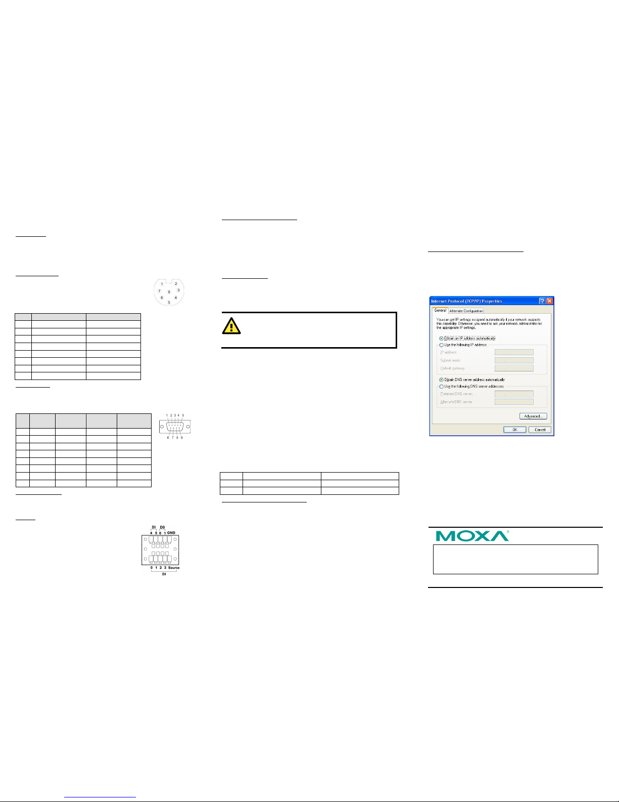
Instructions for Windows Users:
1. Go to [Star t] [Network Connections].
2. Right-click Network Connections and click Properties. Next,
select Internet Protocol (TCP/IP), and then click
Properties.
3. Click OK after inputting the proper IP address and netmask.
NOTE: Refer to the User’s Manual for additional
configuration information.
 Loading...