

Page 1
– 1 – – 2 – – 3 –
P/N: 1802024260010
*1802024260010*
V2426A Series
Quick Installation Guide
First Edition, April 2015
Overview
The V2426A-C2 uses the Intel® Celeron® 1047UE processor and
the V2426A-C7 uses the Intel® Core™ i7-3517UE processor. Both
models feature 4 RS-232/422/485 serial ports, dual 10/100/1000
Mbps LAN ports, 3 USB 2.0 hosts, and 2 CFast sockets. The
computers provide 2 DVI-I outputs, making them particularly
well-suited for industrial applications such as rolling stock, SCADA,
and automation systems.
Most importantly, the V2426A computers come with two expansion
slots that enable you to install V2400A s eries expansion modules
(for example, a 2-port CAN modul e, an HSDPA/GPS/WLAN module,
an 8+8 port digital input/output module, a 2-port serial mo dule, a
mini PCI expansion module, or a mini-PCI Express module),
providing grea ter flexibility for setting up various railway
applications.
Package Checklist
Before installin g your V2426A computer, verify that the package
contains the fo llowing items:
• V2426A series embedded computer
• Wall mounting kit
• Documentation and software CD or DVD
• Quick installat ion guide (printe d)
• Warranty card
NOTE: Please notify your sales representative if any of the above
items are missing or damaged.
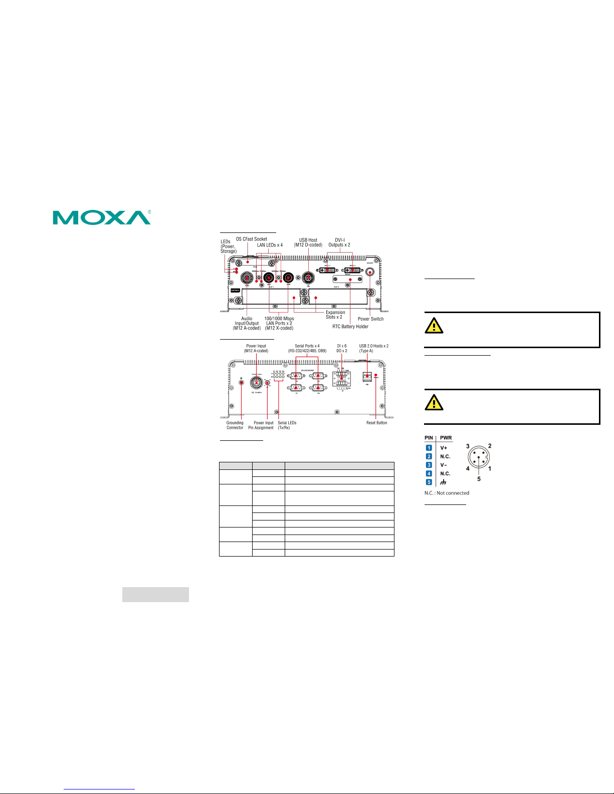
V2426A Panel Layout
V2426A Front View
V2426A Rear View
LED Indicators
The following t able describes th e LED indicator s located on the
front and rear pan els of the V2426A .
LED Name LED Color LED F unction
Power Green Power is on and functioning normally.
Off Power is off or power error exists.
Storage Yellow CFast
card/HDD/SSD is transmitting data
Off
CFast card/HDD/SSD is not transmitting
data
LAN (1 or 2) Green 100 Mbps Ethernet mode
Yellow 1000 Mbps Ethernet mode
Off 10 Mbps or no act ivity
TX (P1-P4) Green Serial port is transmitting dat a
Off Serial port is not transmitting data
RX (P1-P4) Yellow Serial port is receiving da ta
Off Serial port is not receiving data
Installing the V2426A
The V2426A can be DIN-rail mou nted, wall moun ted, or VESA
mounted. Some mounting kits may need to be purchased
separately. Refer to the V2426A Hardware User’s Manual for
detailed insta llation instruct ions.
Connector Description
Power Connector
Connect the 12 to 48 VDC LPS or Class 2 power line to the V242 6A
M12 A-coded power connector. If the power is supplied properly,
the Power LED will light up. The OS is ready when the Ready LED
glows a solid green.
ATTENTION
The branch circuit overcurrent protection must be rated
at
a maximum of 5 A.
Grounding the V2426A
Grounding and wire routing help limit the effects of noise due to
electromagnetic interference (EMI). Run the ground connection
from the ground screw to the grounding surface prior to connecting
the power.
ATTENTION
This product is intended to be mounted to a well-
grounded
mounting surface, such as a metal panel.
SG: The Shielded Ground (sometimes
called Protected Ground) contact is the
central pin of the power input
connector . Connect the SG wire t o an
appropriate grounded metal surface.
DVI-I Outputs
The V2426A comes with 2 DVI-I female connectors for the DVI
display. These output interfaces are all located on the front panel
of the product. Be sure to use the c orrect cable to connect the
computer to the display.
Page 2
– 4 – – 5 – – 6 –
www.moxa.com/support
The Americas: +1-714-528-6777 (toll-free: 1-888-669-2872)
Europe:
+49-89-3 70 03 99-0
Asia-Pacific: +886-2-8919-1230
China:
+86-21-5258-9955 (toll-free: 800-820-5036)
2015 Moxa Inc. All rights reserved.
CFast Slot
The V2426A has 2 CFast sockets. One slot is located on the front
panel for OS storage and the other slot is located inside the
V2426A for backup storage. Both slots support CFast Type-I/II
with DMA mode.
To install an OS CFast card, remove the outer cover and insert the
CFast card in the socket. When finished, push the cover into the
socket and refasten the screws.
To install a CFast card for backup storage, purchase a CFast card
through Moxa’s CTO* service. Refer to the V2426A datasheet for
more information.
*CTO = Configure to order
USB Hosts
The V2426A has one USB port wit h an M12 D-coded connector on
the front panel, and two USB ports with type A connectors on the
rear panel. These USB ports can be used to connect flash disks for
storing large amounts of data.
SATA Connect or
The V2426A has 1 SATA-I/II connector for 2.5" SSD/HDD storage
expansion. To expand storage capacity, purchase an SSD/HDD and
an internal storage kit* through Moxa’s CTO** se rvice.
*This must be purchased separately to install an SSD / HDD. For
details, check the optional accessories section of the V2426A
datasheet.
**CTO = Configure to order
Expansion Slots
The V2426A computers come with two expansion slots that
supports different communication modules (for example, 2-port
CAN module, or HSDPA, GPS, or WLAN module) to provide
additional flex ibility.
To remove an expansion module, first turn off the V2426A and
remove the screws that secure the expansion module to the chassis;
then, pull to remove the expansion module from the V2426A.
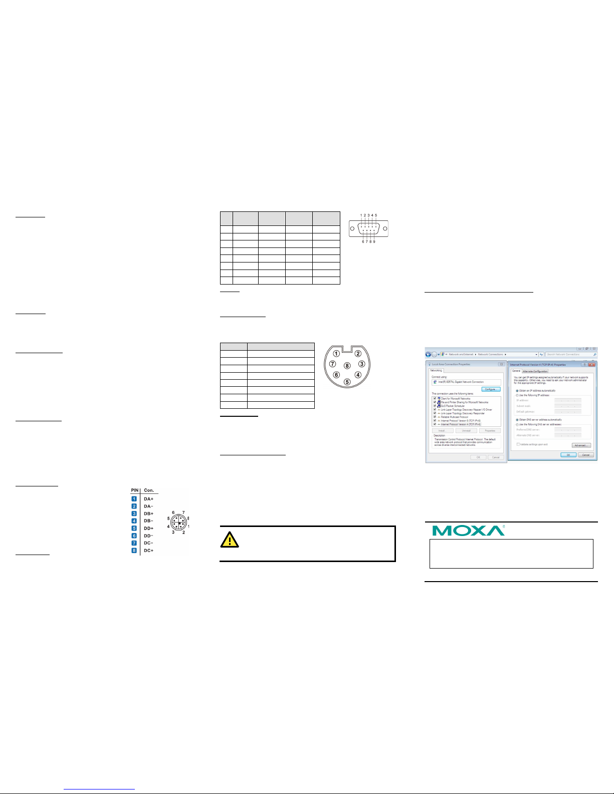
Ethernet Ports
Two 10/100/1000 Mbps Ethernet ports
using M12 X-coded connectors are
located on the fro nt panel. The pin
assignments are shown in the figure.
Serial Ports
The serial ports use DB9 connectors. Each port can be configured
by software for RS-232, RS-422, or RS-485. The pin assignments
for the por ts are shown in the following table.
Pin RS-232 RS-422 RS-48 5
(4-wire)
RS-485
(2-wire)
1 DCD TxDA(-) TxDA(-) –
2 RxD TxDB(+) TxDB(+) –
3 TxD RxDB(+) RxDB(+) DataB(+)
4 DTR RxDA(-) RxDA(-) DataA(-)
5 GND GND GND GND
6 DSR – – –
7 RTS – – –
8 CTS – – –
DI/DO
The V2426A com es with a 6-ch digital input and 2-ch digital output
on the terminal block connectors.
Audio Int erface
The V2426A comes with an M12 A-coded audio connector for audio
input and audio output, allowing users to connect a speaker or an
earphone.
Pin No. A udio
1 Line in – Right
2 GND
3 Line in – Jack Detect
4 Line in – Left
5 Line out – Left
6 Line out – Jack Detect
7 Line out – Right
8 GND
Reset Button
Press the “Reset Button” on the rear panel of the computer to
reboot the system. The Ready LED blinks for the first 5 seconds,
and then turns steady on after the system has rebooted
successfully.
Real-Time Clock (RTC)
The V2426A’s real-time clo ck is powered by a lithium batter y. You
can easily r eplace the battery yourself using an optional battery
kit*. Howe ver, please note that there is a risk of explosion if the
battery is replaced by an incorrect type of battery. Refer to the
V2426A Hardware User's Manual or contact a qualified Moxa
support engineer if you have any questions about the RTC battery.
*Moxa offers an “RTC battery kit” that you can use to easily replac e
the battery. For details, check the optional accessories section of
the V2426A datasheet.
ATTENTION
There is a risk of explosion if the battery is repla ced by a
battery of the incorrect type.
Powering on the V2426A
To power on the V2426A, connect the power cable to the V2426A’s
M12 A-coded power connector (located on the rear panel). Press
the power button to turn on the computer. Note that the Shielded
Ground wire should be connected to the central pin of the
connector. It takes about 30 seconds for the system to boot up.
Once the system is ready, the Power LED will light up.
Configuring the Ethernet Interface
W7E users should follow these steps:
1. Go to Sta rt > Control Panel > Network and Internet >
View network status and tasks
Change adapter
setting.
2. In the Local Area Connection Properties screen, click Internet
Protocol (TCP/IP) and then select Properties. Select
Internet Protocol Version 4, and then click Properties.
3. Click OK after inputting the proper IP address and netmask.
 Loading...