

Page 1
V2426A
Instruction Guide
Installing a SATA Solid-State Drive/Hard Disk
Drive (SSD/HDD) in a Moxa V2426A
Edition 1.0, April 2017
Technical Support Contact Information
www.moxa.com/support
Moxa Americas:
Toll
-free: 1-888-669-2872
Tel:
1-714-528-6777
Fax:
1-714-528-6778
Moxa China (Shanghai office):
Toll
-free: 800-820-5036
Tel:
+86-21-5258-9955
Fax:
+86-21-5258-5505
Moxa Europe:
Tel:
+49-89-3 70 03 99-0
Fax:
+49-89-3 70 03 99-99
Moxa Asia-Pacific:
Tel:
+886-2-8919-1230
Fax:
+886-2-8919-1231
Moxa India
:
Tel:
+91-80-4172-9088
Fax:
+91-80-4132-1045
2017 Moxa Inc. All rights reserved.
Page 2

- 2 -
Table of Contents
1. General Introduction ....................................................... - 3 -
2. Preparing to Install an SSD/HDD .................................... - 3 -
2.1 Working Environment ................................................. - 3 -
2.2 Required Tools .......................................................... - 3 -
2.3 Required Parts .......................................................... - 4 -
3. Installation Flowchart ..................................................... - 5 -
4. Installing a SATA Hard Disk ............................................. - 5 -
4.1 Opening the V2426A to Access the SSD/HDD Area .......... - 5 -
4.2 Installing or Replacing an SSD/HDD ............................ - 11 -
4.2.1 Installing an SSD/HDD in the HDD Tray ............ - 11 -
4.2.2 Removing an Existing SSD/HDD ....................... - 14 -
4.3 Installing the SSD/HDD Assembly ............................... - 18 -
4.4 Reassembling the V2426A Housing .............................. - 21 -
5. Testing the Newly Installed SSD/HDD ........................... - 24 -
Page 3
- 3 -
1. General Introduction
• This guide will help you install a new 2.5" SATA SSD/HDD
storage device or replace an existing SSD/HDD in your Moxa
V2426A.
• If you want to install a new 2.5" SATA SSD/HDD storage device
in your V2426A, refer to section 4.2.1.
• To replace an existing 2.5" SATA SSD/HDD storage device in
your V2426A, refer to section 4.2.2.
• Estimated installation time is 30 to 45 minutes.
2. Preparing to Install an SSD/HDD
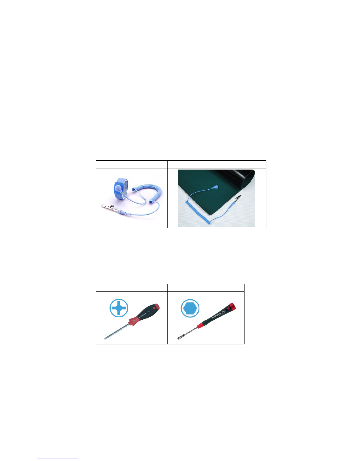
2.1 Working Environment
We recommend setting up a working environment with anti
electro-static discharge (ESD) equipment as shown in Table 1 for
installing the SATA hard disk.
1. Antistatic wrist strap
2. Static dissipative rubber mat
Table 1
2.2 Required Tools
We recommend using appropriate tools and equipment for the
procedures described throughout this guide. Some frequently used
tools are listed below:
1. Phillips screwdriver
2. Hexagon nut driver
Table 2
Page 4
- 4 -
2.3 Required Parts
2.3.1 You will require the following parts to install a new
SSD/HDD:
• Hard disk installation package
(Moxa Ordering No.: FK-75125-02)
• SATA SSD/HDD
(Refer to the V2400A Component Compatibility Guide
for compatible models.)
2.3.2 To replace an existing SSD/HDD, you will require the
following:
• SATA SSD/HDD
(Refer to the V2400A Component Compatibility Guide
for compatible models.)
NOTE
For additional details visit Moxa’s website or contact your Moxa
Distributor and Moxa sales office.
Page 5
- 5 -
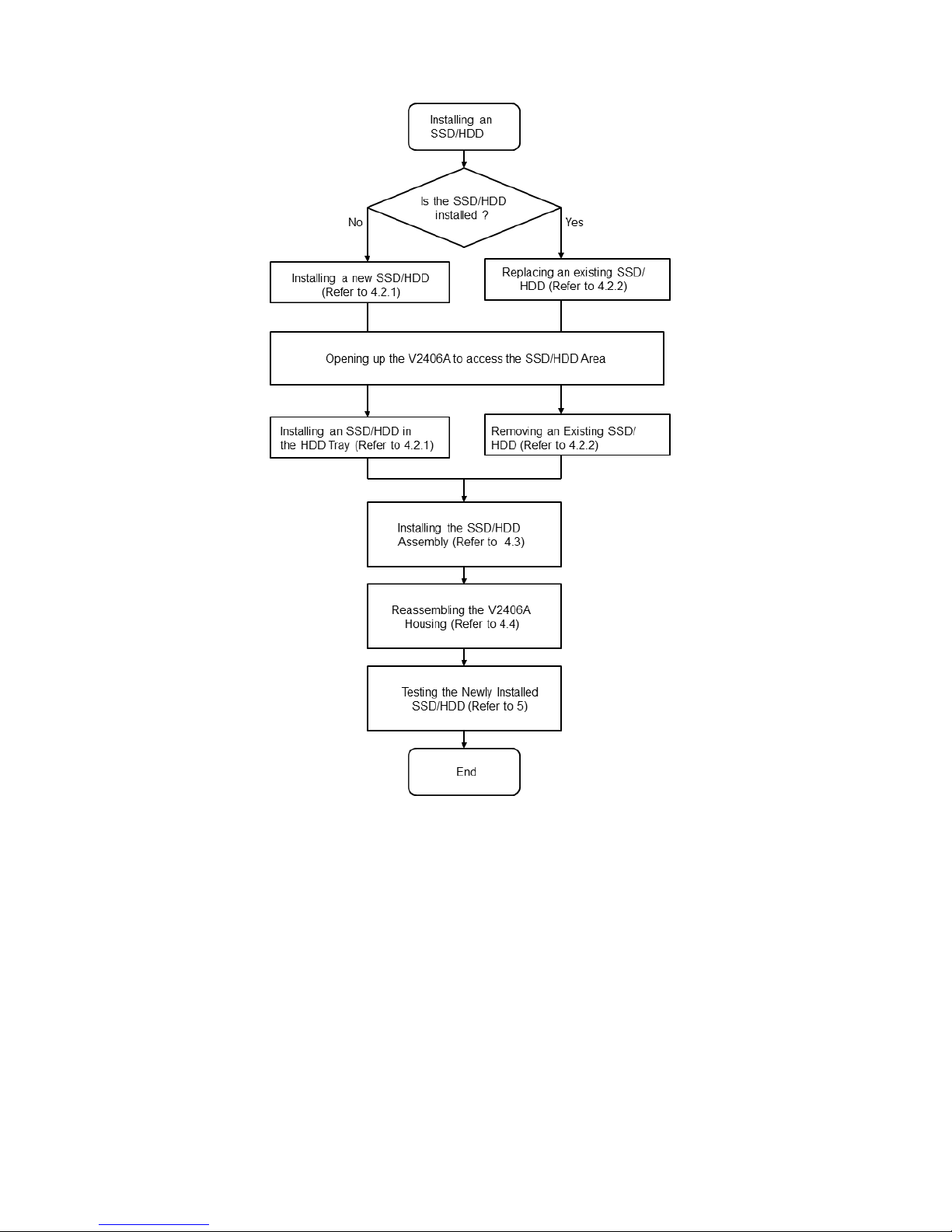
3. Installation Flowchart
4. Installing a SATA Hard Disk
Installing a SATA hard disk involves first removing the bottom cover
of the V2426A to access the SSD/HDD installation area on the main
board, installing an SSD/HDD assembly, and reassembling the
V2426A by putting back the cover and securing it with screws.
4.1 Opening the V2426A to Access the SSD/HDD Area
The SSD/HDD area is located inside the V2406A, which can be
reached by opening up the cover as per the following instructions:
Page 6
- 6 -
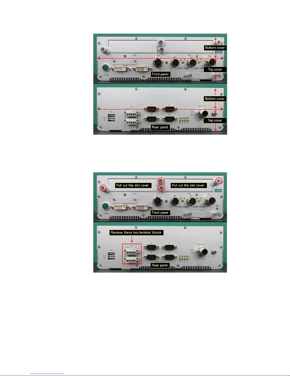
4.1.1 Place the V2426A upside down on the working area as
shown in Figure 1.
Figure 1
4.1.2 Use a Phillips screwdriver (item 1 in Table 2) to loosen the
four (4) screws on the front panel and then pull out two
expansion slot covers. Remove the two terminal blocks on
the rear panel as shown in Figure 2.
Figure 2
Page 7
- 7 -
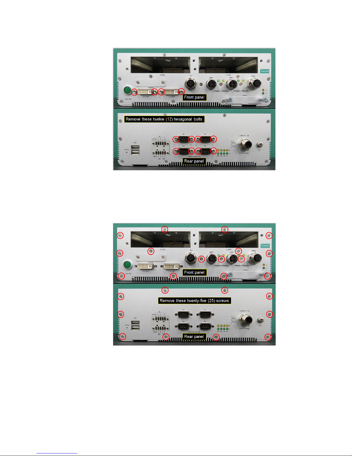
4.1.3 Use a hexagon nut driver (item 2 in Table 2) to remove the
eight (12) hexagon screws (indicated with red circles) on the
front and rear panels as shown in Figure 3.
Figure 3
4.1.4 Use a Phillips screwdriver (item 1 in Table 2) to remove the
twenty-five (25) screws (indicated with red circles) on the
front and rear panels as shown in Figure 4.
After removing the screws, place the V2426A such that its
rear panel is facing towards you.
Figure 4
Page 8
- 8 -
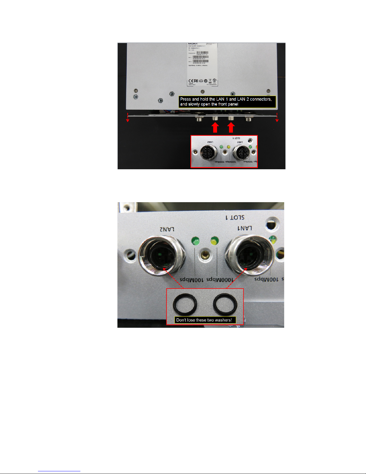
4.1.5 Press and hold the LAN1 and LAN2 connectors and partially
open the front panel as shown in Figure 5.
Figure 5
Keep the O-rings on the LAN1 and LAN2 connectors safely
and do not lose them.
Figure 6
Page 9

- 9 -
4.1.7 Gently open the front and rear panels partially as shown in
Figure 7. Refer to Figure 8 and Figure 9 to avoid pulling out
any wires or cables connected to the front and rear panels.
Figure 7
Figure 8
Page 10

- 10 -
Figure 9
4.1.8 Place the rear panel vertically beside the computer on the
right side without pulling out the wires as shown in Figure 10
and use a Philips screwdriver (item 1 in Table 2) to remove
the four (4) screws indicated with red circles in Figure 10.
Figure 10
Page 11

- 11 -
4.1.9 Slide out the bottom cover of the V2426A completely as
shown in Figure 11.
Figure 11
4.2 Installing or Replacing an SSD/HDD
4.2.1 Installing an SSD/HDD in the HDD Tray
Follow the instructions detailed below to install an SSD/HDD in the
HDD tray to build the SSD/HDD assembly:
4.2.1.1 Arrange all the components from the hard disk installation
package as shown in Figure 12.
Figure 12
Page 12

- 12 -
4.2.1.2 Slide in the yellow anti-shock pads into the side notches
provided on the HDD tray as shown in Figure 13.
Figure 13
4.2.1.3 Turn the SATA connector clockwise by 90 degrees and
gently insert the connector head into the opening on the
HDD tray until it completely passes through the opening
as shown in Figure 14 and Figure 15.
Figure 14
Figure 15
Page 13

- 13 -
4.2.1.4 Connect the SATA cable with the SSD/HDD and fix the
SSD/HDD to the tray as shown in Figure 16.
Figure 16
4.2.1.5 Use a Phillips screwdriver (item 1 in Table 2) to tighten the
four (4) screws to secure the SSD/HDD on to the tray as
shown in Figure 17.
Figure 17
Page 14

- 14 -
4.2.2 Removing an Existing SSD/HDD
4.2.2.1 Disconnect the SATA data cable from the main board as
shown in Figure 18.
Figure 18
4.2.2.2 Disconnect the SATA power cable from the main board as
shown in Figure 19.
Figure 19
Page 15

- 15 -
4.2.2.3 Use a Phillips screwdriver (item 1 in Table 2) to remove
the four (4) screws that attach the SSD/HDD assembly to
the board as shown in Figure 20.
Figure 20
4.2.2.4 Gently pull out the SSD/HDD assembly as shown in Figure
21.
Figure 21
Page 16

- 16 -
4.2.2.5 Use a Phillips screwdriver (item 1 in Table 2) to remove
the four (4) screws on the HDD tray as shown in Figure
22.
Figure 22
4.2.2.6 Disconnect the SATA cable from the SSD/HDD and
remove the SSD/HDD as shown in Figure 23.
Figure 23
Page 17

- 17 -
4.2.2.7 Connect the SATA cable to the new SSD/HDD and fix the
SSD/HDD to the tray as shown in Figure 24.
Figure 24
4.2.2.8 Use a Phillips screwdriver (item 1 in Table 2) to tighten the
screws (4 nos.) to secure the SSD/HDD to the tray as
shown in Figure 25.
Figure 25
Page 18

- 18 -
4.3 Installing the SSD/HDD Assembly
To install the SSD/HDD assembly in the installation area on the main
board, do the following:
4.3.1 Use a Phillips screwdriver to remove the black screw located
in the SSD/HDD area on the main board as shown in Figure
26.
Figure 26
4.3.2 Move the cable tie that is holding the wire aside as shown in
Figure 27.
Figure 27
Page 19

- 19 -
4.3.3 Place the SSD/HDD assembly on top of the four pillars in the
installation area and put back cable tie as shown in Figure
28.
Figure 28
4.3.4 Use a Phillips screwdriver to tighten the four (4) screws to fix
the SSD/HDD assembly to the board as shown in Figure 29.
Figure 29
Page 20

- 20 -
4.3.5 Connect the free end of the SATA power cable to the
mainboard as shown in Figure 30.
Figure 30
4.3.6 Connect the free end of the SATA data cable to main board
as shown in Figure 31.
Figure 31
Page 21

- 21 -
4.4 Reassembling the V2426A Housing
After you have installed the SSD/HDD assembly on the main board,
you must reassemble the V2406A housing and secure the same with
screws as follows:
4.4.1 Slide in the bottom cover of the V2426A from front panel
towards rear panel as shown in Figure 32. Do this gently and
carefully to avoid bending or damaging any wires/cables or
fixtures.
Figure 32
4.4.2 Align the bottom cover with the position of top cover as
shown in Figure 33.
Figure 33
Page 22

- 22 -
4.4.3 Gently rotate the rear panel clockwise and place it vertically
beside the computer on the right side without pulling out the
wires as shown in Figure 34 and use a Phillips screwdriver to
tighten the four (4) screws marked with red circles.
Figure 34
4.4.4 Push the front panel back in place, put back the rare panel,
and use a Phillips screwdriver to tighten the twenty five (25)
screws marked with red circles as shown in Figure 35.
Figure 35
Page 23

- 23 -
4.4.5 Use a hexagon nut driver to tighten the twelve (12) hexagon
screws marked with red circles on the front and rear panels
as shown in Figure 36.
Figure 36
4.4.6 Push in the expansion slot covers on the front panel and use
a Philips screwdriver to tighten the four (4) screws on the
expansion slot covers as shown in Figure 37. Insert the two
terminal blocks on the rear panel.
Figure 37
Page 24

- 24 -
4.4.7 Put back the o-rings onto the LAN1 and LAN2 connectors,
and tighten the LAN cables (M12 X-coded) completely.
Figure 38
5. Testing the Newly Installed SSD/HDD
To verify that the SSD/HDD that you just installed is working fine,
perform the following checks:
5.1 Enter the BIOS setup utility by pressing the F2 key while the system
is booting up. The main BIOS Setup screen is displayed. Click SCU to
enter the BIOS configuration.
Figure 39
Page 25

- 25 -
5.2 In the configuration screen, select Advanced HDC
Configuration as shown in Figure 40.
Figure 40
5.3 Verify the information [brand and model] displayed for Serial ATA
Port 3 as shown in Figure 41.
Figure 41
Page 26

- 26 -
5.4 Select Exit Exit Discarding Changes to exit the BIOS
configuration utility.
Figure 42
The SSD/HDD installation process is complete. You can now start
using the disk.
 Loading...