

Page 1

V2401/2402 Hardware User’s Manual
Fourth Edition, September 2011
www.moxa.com/product
© 2011 Moxa Inc. All rights reserved.
Reproduction without permission is prohibited.
Page 2

V2401/2402 Hardware User’s Manual
The software described in this manual is furnished under a license agreement and may be used only in accordance with
the terms of that agreement.
Copyright Notice
Copyright ©2010 Moxa Inc.
All rights reserved.
Reproduction without permission is prohibited.
Trademarks
The MOXA logo is a registered trademark of Moxa Inc.
All other trademarks or registered marks in this manua l belong to their res pec ti v e manufacturers.
Disclaimer
Information in this document is subject to change witho ut no tic e a nd doe s not repres e nt a co mmitment o n the part of
Moxa.
Moxa provides this document as is, without warranty of any kind, either expressed or implied, including, but not limited
to, its particular purpose. Moxa reserves the rig ht to make impro vem e nts and/o r changes to this manual, or to the
products and/or the programs described in this manual, at any time .
Information provided in this manual is intended to be accurate and reliable. However, Moxa assumes no responsibility for
its use, or for any infringements on the rights of third parties that may res ult fr om its use.
This product might include unintentional technic a l o r typographical errors. Changes are periodically made to the
information herein to correct such error s , and these changes are inc or pora te d into new editions of the publication.
Technical Support Contact Information
www.moxa.com/support
Moxa Americas
Toll
-free: 1-888-669-2872
Tel:
+1-714-528-6777
Fax:
+1-714-528-6778
Moxa China (Shanghai office)
Toll
-free: 800-820-5036
Tel:
+86-21-5258-9955
Fax:
+86-21-5258-5505
Moxa Europe
Tel:
+49-89-3 70 03 99-0
Fax: +49-89-3 70 03 99-99
Moxa Asia
-Pacific
Tel:
+886-2-8919-1230
Fax: +886-2-8919-1231
Page 3

Table of Contents
1. Introduction ...................................................................................................................................... 1-1
Overview ........................................................................................................................................... 1-2
Package Checklist ............................................................................................................................... 1-2
Product Features ................................................................................................................................ 1-3
V2401/2402 Hardware Specifications .................................................................................................... 1-3
Hardware Block Diagram ..................................................................................................................... 1-5
2. Hardware Introduction...................................................................................................................... 2-1
Appearance ........................................................................................................................................ 2-2
Dimensions ........................................................................................................................................ 2-2
LED Indicators .................................................................................................................................... 2-3
Reset Button ...................................................................................................................................... 2-3
Real Time Clock .................................................................................................................................. 2-3
3. Hardware Connection Description ..................................................................................................... 3-1
Installing the V2401/2402 ................................................................................................................... 3-2
Wiring Requirements ........................................................................................................................... 3-5
Connecting the Power .................................................................................................................. 3-5
Grounding the Unit ...................................................................................................................... 3-5
Connecting Data Transmission Cables ................................................................................................... 3-6
Connecting to the Network ........................................................................................................... 3-6
Connecting to a Serial Device ....................................................................................................... 3-6
Installing a CompactFlash Card ............................................................................................................ 3-7
Connecting a PS/2 Keyboard and Mouse ................................................................................................ 3-8
Connecting to the USB Device .............................................................................................................. 3-9
DI/DO ............................................................................................................................................... 3-9
Connecting to a VGA Monitor .............................................................................................................. 3-10
Connecting to an LVDS Monitor .......................................................................................................... 3-10
Connecting to a DVI-I Monitor ............................................................................................................ 3-11
Connecting to a Speaker or a Headphone ............................................................................................ 3-11
Upgrading the Memory Module ........................................................................................................... 3-12
Upgrade the DOM Module .................................................................................................................. 3-13
Installing a SATA Hard Disk ............................................................................................................... 3-14
4. BIOS Setup ........................................................................................................................................ 4-1
Entering the BIOS Setup Utility ............................................................................................................ 4-2
Modifying the BIOS Main Settings ......................................................................................................... 4-2
Basic Configuration ...................................................................................................................... 4-2
System Security .......................................................................................................................... 4-3
Advanced Settings .............................................................................................................................. 4-4
Hard Disk Boot Priority ................................................................................................................. 4-4
Advanced BIOS Features .............................................................................................................. 4-4
CPU Features .............................................................................................................................. 4-5
C1E Function ....................................................................................................................... 4-5
EIST Function ...................................................................................................................... 4-5
Hyper-Thread ing Te c hnolo gy ................................................................................................. 4-5
Quick Power On Self Test ...................................................................................................... 4-5
Summary Screen Show ......................................................................................................... 4-5
Advanced Chipset Settings ........................................................................................................... 4-5
On-chip Frame Buffer Size .................................................................................................... 4-6
DVMT Mode ......................................................................................................................... 4-6
DVMT/FIXED Memory Size .................................................................................................... 4-6
Boot Display ........................................................................................................................ 4-6
LVDS Function ..................................................................................................................... 4-6
Panel Number ...................................................................................................................... 4-6
Peripherals......................................................................................................................................... 4-7
OnChip IDE Device ...................................................................................................................... 4-7
On-Chip Channel 0 PCI IDE ................................................................................................... 4-7
IDE Channel 0 Master UDMA ................................................................................................. 4-7
IDE Channel 0 Slave UDMA ................................................................................................... 4-7
On-Chip Channel 1 PCI IDE ................................................................................................... 4-8
IDE Channel 1 Master UDMA ................................................................................................. 4-8
IDE Channel 1 Slave UDMA ................................................................................................... 4-8
Onboard Device .......................................................................................................................... 4-8
Onboard Audio..................................................................................................................... 4-8
Onboard LAN Boot ROM ........................................................................................................ 4-8
Super I/O Device ......................................................................................................................... 4-9
Debug Port .......................................................................................................................... 4-9
Power on After Power Fail ..................................................................................................... 4-9
Page 4

Power ................................................................................................................................................ 4-9
ACPI Suspend Type ................................................................................................................... 4-10
Soft-Off by PWR-BTTN ............................................................................................................... 4-10
Hardware Monitor ............................................................................................................................. 4-10
CPU Warning Temperature ......................................................................................................... 4-10
Warning Beep ........................................................................................................................... 4-10
Load Defaults ................................................................................................................................... 4-11
Load System Default Settings ..................................................................................................... 4-11
Load System Turbo Settings ....................................................................................................... 4-11
Load CMOS from BIOS ............................................................................................................... 4-11
Save CMOS to BIOS ................................................................................................................... 4-11
Exiting the BIOS Setup ...................................................................................................................... 4-11
Save & Exit Setup ..................................................................................................................... 4-12
Exit Without Saving ................................................................................................................... 4-12
Upgrading the BIOS .......................................................................................................................... 4-12
A. Regulatory Appr ov al S tateme nt ........................................................................................................ A-1
Page 5

1
1. Introduction
The V2401/2402 Series embedded computers are based on the Intel Atom N270 x86 processor, and feature
four RS-232/422/485 serial ports, ei g h t RS-232 serial ports, dual Gigabit LAN ports, six USB 2.0 hosts, and a
CompactFlash socket. The V2401 computer provides VGA, DVI, and LVDS outputs, and the V2402 computer
provides both VGA and DVI outputs, making them particularl y well-s uite d for ind us trial applications such as
SCADA and manufacturing automation.
The V2401 and V2402 come with four RS-232/422/485 serial ports , and the V2401 has an additional eight
RS-232 ports, making them ideal for connecting a wide range of serial devices. The dual 10/10 0/1000 Mbps
Ethernet ports offer a reliable solution fo r netwo rk redund a nc y , pro mis ing continuous operations for data
communication and management. As an added convenience, the V2 401 /24 02 co mputers have four DIs and
four DOs for connecting digital input/output devices.
In addition, the CompactFlash and USB sockets prov ide the V2400 compute rs with the reliability needed for
industrial applications that re quir e d ata buff er ing and storage expansion.
Pre-installed with Linux, Windows CE 6.0, or Windows Embedd ed Stand ard 2009 , the V2401/24 02 Ser ie s
provides programmers with a friendly environment for developing sophisticated, bug-free application software
at a low cost.
The V2402 series also offers models that support -40 to 70°C operating temperature for harsh environments.
The following topics are covered in this chapter :
Overview
Package Checklist
Product Features
V2401/2402 H ar d war e Specifications
Hardware Block Diagram
Page 6

V2401/2402 HW User's Manual Introduction
1-2
Overview
The V2401 and V2402 come with four RS-232/422/485 serial ports, and the V2401 has an additional eight
RS-232 ports, making them ideal for connecting a wide range of serial devices, and the dual 10/100/1000 Mbps
Ethernet ports offer a reliable solution fo r netwo rk redund a nc y , pro mis ing continuous operations for data
communication and management. As an added convenience, the V2 401 /24 02 co mputers have 4 DIs, and 4
DOs for connecting dig ita l input/o utp ut d e vices.
In addition, the CompactFlash and USB sockets prov ide the V2400 compute rs with the reliability needed for
industrial applications that re quir e d ata buff er ing and storage expansion.
Pre-installed with Linux, Windows CE 6.0, or Windows Embedd ed Stand ard 2009 , the V2401/24 02 Ser ie s
provides programmers with a friendly environment for developing sophisticated, bug-free application software
at a low cost.
In addition, the V2402 series also offers -40 to 70 ° C w i de temperature models for harsh environments.
Package Checklist
The V2401/2402 Series includes the following models:
V2401-CE:
x86 ready-to-run embedded computer with Intel Atom N270, VGA, LVDS, DVI, Audio, 2 LANs, 12 serial ports,
4 DIs, 4 DOs, 6 USB 2.0 ports, CF, WinCE 6.0
V2401-XPE:
x86 ready-to-run embedded computer with Intel Atom N270, VGA, LVDS, DVI, Audio, 2 LANs, 12 serial ports,
4 DIs, 4 DOs, 6 USB 2.0 ports, CF, Windows Embedded Standard 2009
V2401-LX:
x86 ready-to-run embedded computer with Intel Atom N270, VGA, LVDS, DVI, Audio, 2 LANs, 12 serial ports,
4 DIs, 4 DOs, 6 USB 2.0 ports, CF, Linux 2.6
V2402-CE:
x86 ready-to-run embedded computer with Intel Atom N270, VGA, DVI, Audio, 2 LANs, 4 serial ports, 4 DIs, 4
DOs, 6 USB 2.0 ports, CF, WinCE 6.0
V2402-XPE:
x86 ready-to-run embedded computer with Intel Atom N270, VGA, DVI, Audio, 2 LANs, 4 serial ports, 4 DIs, 4
DOs, 6 USB 2.0 ports, CF, Windows Embedded Standard 2009, -10 to 60°C operating temper ature
V2402-LX:
x86 ready-to-run embedded computer with Intel Atom N270, VGA, DVI, Audio, 2 LANs, 4 serial ports, 4 DIs, 4
DOs, 6 USB 2.0 ports, CF, Linux 2.6, -10 to 60°C operating temperature
V2402-T-XPE:
x86 ready-to-run embedded computer with Intel Atom N270, VGA, DVI, Audio, 2 LANs, 4 serial ports, 4 DIs, 4
DOs, 6 USB 2.0 ports, CF, Windows Embedded Standard 2009, -40 to 70°C operating temper ature
V2402-T-LX:
x86 ready-to-run embedded computer with Intel Atom N270, VGA, DVI, Audio, 2 LANs, 4 serial ports, 4 DIs, 4
DOs, 6 USB 2.0 ports, CF, Linux 2.6, -40 to 70°C operating temperature
Each model is shipped with the following items :
• 1 V2401 or V2402 computer
• Terminal block to power jack converter
• PS2 to KB/MS Y-type cable
• Wall mounting kit
• Documentation & Software CD or DVD
• Quick Installation Guide (printed)
Page 7

V2401/2402 HW User's Manual Introduction
1-3
• Product Warranty Statement (printed)
NOTE: Please notify your sales representative if any of the above items are missing or damaged.
Product Features
V2401/2402 series embedded computers have the following features:
• DDR2 SODIMM socket, supporting DDR2 533 up to 2 GB (max. )
• Dual independent display (VGA, DVI, LVDS selectable) (V2401: VGA, DVI and LVDS; V2402: VGA and DVI)
• Gigabit Ethernet ports
• RS-232/422/485 serial ports, supporting non-standard baudrates
• 8 RS-232 serial ports (V2401 only)
• 6 USB 2.0 ports for high speed peripherals
• DIs, 4 Dos
• CompactFlash socket for storage expansion
• Ready-to-run Embedded Linux, Wi nd ow s CE 6.0, or Windows Embe dd ed Stand ard 2009 platf orm
• -40 to 70°C wide temperature mod e ls av aila b le (V240 2-T models)
V2401/2402 Hardware Specifications
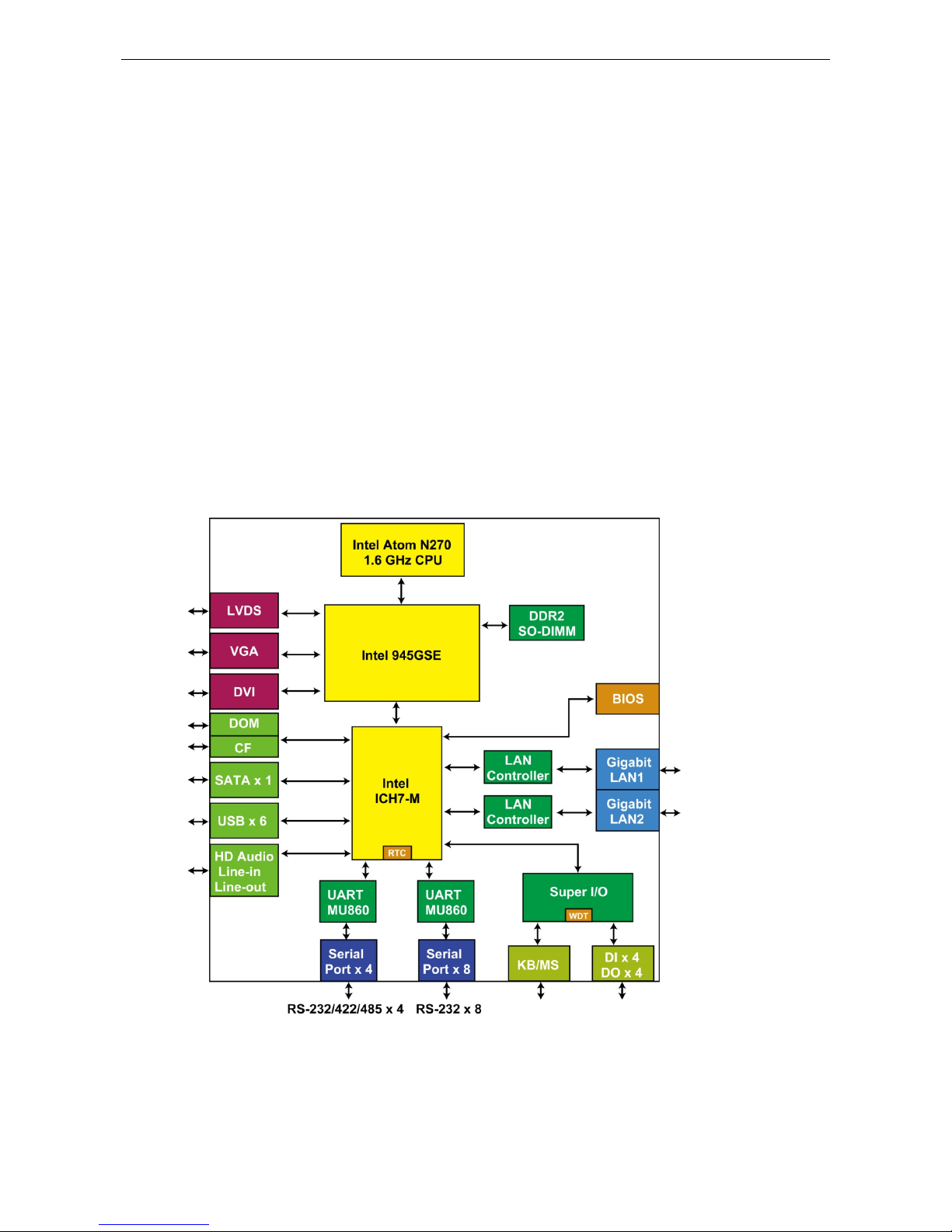
Computer
CPU:
Intel Atom N270 1.6 GHz processor
OS (pre
-installed): Linux, Windows CE 6.0 or Windows Embedded Standard 2009
System Chipset:
Intel 945GSE + ICH7-M
BIOS:
8 Mbit Flash BIOS, SPI type, ACPI function supported
FSB:
400/533 MHz
System Memory:
1 x 200-pin DDR2 SODIMM socket support DDR2 533 up to 2 GB, built-in 1 GB
USB:
USB 2.0 compliant hosts x 6, type A connector, supports system boot up
Storage
Built
-in: 2 GB onboard industrial DOM to store OS
Storage
Expansion: CompactFlash socket for CF card expansion, supporting CF Type-
I/II socket with DMA
mode
HDD Support:
1 SATA-II connector for HDD expansion
Other Peripherals
KB/MS:
1 PS/2 interface supporting standard PS/2 keyboard and mouse throug h Y -type cable
Audio:
HD audio, with line-in and line-out interface
Display
Graphics Controller: Intel Gen 2.5 Integrated Graphics Engine, 250 MHz core render clock and 200 MHz core
display clock at 1.05
-V core voltage
VGA Interface:
DB15 female connector
LVDS Interface: Onboard HIROSE DF13-40DP-1.25 V connector (V2401 only)
DVI Interface:
DVI-connector (chrontel CH7307 SDVO to DVI transmitter)
Ethernet Interface
LAN:
2 auto-sensing 10/100/1000 Mbps ports (RJ45)
Serial Interface
Serial Standards:
• V2401/2402: 4 RS
-232/422/485 ports*, softwa re sel ectable (DB9 male connector)
• V2401 only: 8 RS-232 ports (68-pin VHDC connector )
*COM1’s pin 9 signal can be set by jumper as N/C (default), +5 V, or +12 V
ESD Prot ection:
4 KV for all signals
Page 8

V2401/2402 HW User's Manual Introduction
1-4
Serial Communication Para me ters
Data Bits:
5, 6, 7, 8
Stop Bits:
1, 1.5, 2
Parity:
None, Even, Odd, Space, Mark
Flow Control:
RTS/CTS, XON/XOFF, ADDC® (automatic data direction control) for RS-485
Baudrate:
50 bps to 921.6 Kbps (non-standard baudrates supported; see user's manual for details)
Serial Signals
RS
-232: TxD, Rx D, DTR, DSR, RTS, CTS, DCD, GND
RS
-422: TxD+, TxD-, RxD+, RxD-, GND
RS
-485-4w: TxD+ , TxD-, RxD+, RxD-, GND
RS
-485-2w: Data+, Data-, GND
Digital Input
Input Channels:
4, source type
Input Voltage:
0 to 30 VDC at 25 Hz
Digital Input Levels for Dry Contacts:
• Logic level 0: Close to GND
• Logic level 1: Open
Digital Input Levels for Wet Contacts:
• Logic level 0: +3 V max.
• Logic level 1: +10 V to +30 V (Source to DI)
Isolation:
3 KV optical
Digital Output
Output Channels: 4, sink type
Output
Current: Max. 200 mA per channel
On
-state Voltage: 24 VDC nominal, open collector to 30 VDC
Connector Type:
10-pin screw terminal block (4 DI points, 4 DO points, DI Source, GND)
Isolation:
3 KV optical isolation
LEDs
System:
Power, Storage
LAN:
100M/Link x 2, 1000M/Link x 2 (on connector)
Switches and Buttons
Power Switch:
on/off (front panel)
Reset Button:
For warm reboot (rear panel)
Physical Characteristics
Housing:
Aluminum
Weight:
• V2401: 2.1 kg
• V2402: 2 kg
Dimensions:
Without
ears: 250 x 57 x 152 mm (9.84 x 2.24 x 5.98 in)
With ears: 275 x 63 x 152 mm (10.83 x 2.48 x 5.98 in)
Mounting:
DIN-Rail, wall, VESA
Environmental Limits
Operating Temperature:
•
Standard models: -10 to 60°C (14 to 140°F)
• Wide temp. models: -40 to 70°C (-40 to 158°F)
Storage Temperature:
-40 to 85°C (-40 to 185°F)
Ambient Relative Humidity:
5 to 95% (non-condensing)
Anti
-vibration: 5 g rms @ IEC-68-2-34, random wave, 5-500 Hz, 1 hr/axis
Anti
-shock: 50 g @ IEC-68-2-27, half sine wave, 11 ms
Power Requiremen t s
Input Voltage:
9 to 36 VDC (3-pin terminal block for V+, V-, SG)
Page 9
V2401/2402 HW User's Manual Introduction
1-5
Power Consumption:
26 W (without LVDS output)
2.9 A @ 9 VDC
1.08 A @ 24 VDC
720 mA @ 36 VDC
Standards and Cer tifications
Safety:
UL 508, UL 609 50-1, CSA C22.2 No. 6 0950-1-07, EN 60950-1, CCC (GB9254, G B17625.1)
EMC: EN 55022 Class A, EN 61000-3-2 Class D, EN 61000-3-3, EN 55024, FCC Part 15 Subpart B Class A
Wheeled Vehicles:
e-Mark (e 4)
Green Product:
RoHS, CRoHS, WEEE
Reliability
Automatic Reboot Trigger:
Built-in WDT (watchdog timer) supporting 1-255 level time interv a l sys te m
reset, software programmable
MTBF (mean time between failures):
V2401: 238,762 hrs
V2402: 228,172 hrs
Warranty
Warranty Period:
3 years
Details: See www.mox a .c om/war r a nty
Hardware Block Diagram
Page 10

2
2. Hardware Introduction
The V2401/2402 series embedded computers are compac t, w e ll-designed, and built rugged enough for
industrial applications. LED indicators help you monitor performance and identify trouble spots, multiple serial
ports allow you to connect different devices for wirele s s opera tio n, a nd the reliab le and s table hard ware
platform lets you devote your attention to developing your applications.
The following topics are covered in this chapter :
Appearance
Dimensions
LED Indicators
Reset Button
Real Time Clock
Page 11
V2401/2402 HW User's Manual Hardware Introduct ion
2-2
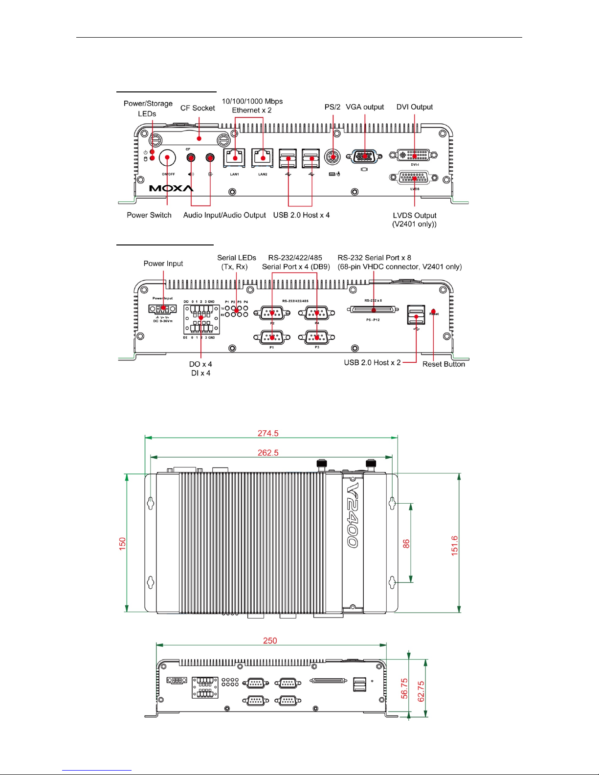
Appearance
V2401/2402 Front View
V2401/2402 Rear View
Dimensions
Page 12

V2401/2402 HW User's Manual Hardware Introduct ion
2-3
LED Indicators
LED Name LED Color LED Function
Power Green Power is on and functioning normally
Off
Power is off or a power erro r ex i s t s
Storage Yellow CF card is detected
Off CF card is not detected
LAN Green 100 Mbps Ethernet mode
Yellow 1000 Mbps (Gigabit) Ethernet mode
Off No activity or 10 Mbps Ethernet mode
Tx1 to Tx4
(P1-P4)
Green Serial ports P1-P4 transmitting data
Off Serial ports P1-P4 not transmitting d ata
Rx1 to Rx4
(P1-P4)
Yellow Serial ports P1-P4 receiving data
Off Serial ports P1-P4 not receiving data
Reset Button
Press the Reset Button on th e rear panel of the V2401/2402 to reboot the system automatically. The Ready
LED will blink on and off for the first 5 seconds, and then maintain a steady glow once the system has rebooted.
The V2401/2402 does not support a “Reset to Default” function.
Real Time Clock
The embedded computer’s real-time clock is powered by a lithium battery. We strongly recommend that yo u
NOT replace the lithium battery on your own. If the battery needs to be changed, please contact the Moxa RMA
service team.
ATTENTION
There is a risk of explosion if the wrong type of battery is used. To avoid this potential danger, always be sure
to use the correct type of battery. Contact the Moxa RMA service team if yo u nee
d to replace your battery.
C
aution
There is a r
isk of explosion if the battery is replaced by an incorrect type. D
ispose of used batteries according
to the instructions
on the battery.
Page 13

3
3. Hardware Connection Description
In this chapter, we show how to connect the embedded computers to the network and to vario us dev ic es.
The following topics are covered in this chapter :
Installing the V2401/2402
Wiring Requirements
Connecting the Power
Grounding the Unit
Connecting Data Transmission Cables
Connecting to the Network
Connecting to a Serial Device
Installing a Compac tF las h C ar d
Connecting a PS/2 Keyboard and Mouse
Connecting to the USB Device
DI/DO
Connecting to a VGA Moni t o r
Connecting to an LVD S Mo nit or
Connecting to a DVI-I Monitor
Connecting to a Speake r or a Headphone
Upgrading the Memory Module
Upgrade the DOM Module
Installing a SATA Hard Disk
Page 14

V2401/2402 HW User's Manual Hardware Connec tion Description
3-2
Installing the V2401/2402
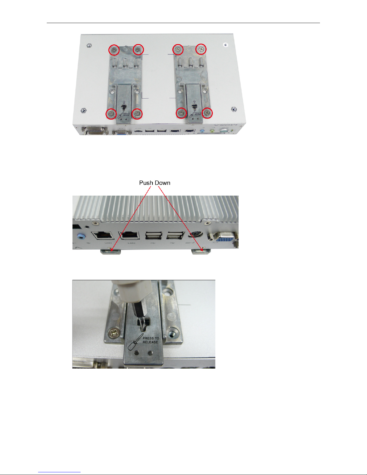
DIN-Rail Mounting
The V2401/2402 can be installed on a DIN-rail with the optional DIN-rail kit. This DIN-rail k it mus t be
purchased separately. It includes two DIN-rai l br ac kets and eight scr ew s .
To attach the DIN-rail kit, turn the V2401/2402 over to the bottom cover. Find the locations for the screws and
place the brackets on the cover. Please note that all eight screws must be firmly attached so that the computer
can be securely installed on the DIN-rail.
Page 15
V2401/2402 HW User's Manual Hardware Connec tion Description
3-3
When the brackets are firmly attached with the screws, it can be installed on a DIN-rail
To release the DIN-rail kit, simply use a screwdriver to push down the lower part. Please use at least two
persons to do this step as once the DIN-rail kit is pushed down, the computer will be de tached im med iate ly
from the DIN-rail.
To re-install the computer on the DIN-rail, use a screwdriver to press the buckle so that it can be released. Now,
it can be re-installed on the DIN-rail.
Page 16

V2401/2402 HW User's Manual Hardware Connec tion Description
3-4
Wall or Cabinet Mounting
The V2401/2402 comes with two metal brackets for attaching it to a wall or the inside of a cabinet.
Step 1: Use two screws for each bracket and attach the bracket to the rear of the V2401/2402.
Step 2: Use two screws per side to attach the V2401/2402 to a wall or cabinet.
VESA Mounting (not included in the Package)
The V2401/2402 has four screw holes on the bottom panel for attaching the computer to a 100 x 100 mm VESA
mounting kit. Use four screws to attach the computer to the VESA mounting k it.
Page 17

V2401/2402 HW User's Manual Hardware Connec tion Description
3-5
Wiring Requirements
This section describes how to connect seria l devices to the embedded computer.
You should read and follow these common safety precautions before proceeding with the ins talla tio n of any
electronic device:
• Use separate paths to route wiring for power and devices. If power wir ing and devic e wir ing p aths must
cross, make sure the wires are perpendicular at the intersectio n po int.
NOTE: Do not run signal or communication wiring together with power wiring in the same wire conduit. To
avoid interference, wires with different signal characteristics should be route d separately.
• Use the type of signal transmitted through a wire to determine which wir e s should be kept separ ate . The
rule of thumb is that wiring that shares similar electrical characteristics can be bundled together.
• Keep input wiring and output wiring separate.
• It is advisable to label the wiring to all devices in the system.
ATTENTION
Safety First!
Be sure to disconnect
the power cord before installing and/or wiring your V2401/2402.
Wiring Caution!
Calculate the maximum possible current in each power wir e and com mon wire . Observe all elec trical codes
dictating the maximum current allowable for e ac h wire si ze .
If the curre
nt goes above the maximum ratings, the wiring could overheat, causing serious damage to your
equipment.
Temperature Caution!
Be careful when handling
the unit. When the unit is plugged in, the
internal components generate heat, and
consequently the outer c
asing may feel hot to the touch.
Connecting the Power
The PC’s power sour ce should be p rovided by a UL listed class 2 or “Limited Power Source” (LPS), with external
adaptor output rated 9 to 36 VDC, 1.8 A @ 9 VDC, 422 mA @ 36 VDC. If the power is supplied properly, the
“Ready” LED will g lo w a solid green after a 25 to 30 second delay.
Grounding the Unit
Grounding and wire routing help limit the effec ts of noise due to electro m agnetic interference (EMI). Before
connecting any devices, run a ground wire from the ground screw to the gro und ing s urf ace.
ATTENTION
This product s
hould be mounted to a well-grounded mounting surface such as a metal panel.
SG: The Shielded Ground (sometimes called Protec ted
Ground) contact is the right most of the 3-pin power
terminal block connector when viewed fro m the angle
shown here. Connect the SG wire to an appropriate
grounded metal surface.
Page 18
V2401/2402 HW User's Manual Hardware Connec tion Description
3-6
Connecting Data Transmission Cables
This section describes how to connect the V2401/2402 embedded c omputers to the network and serial devices.
Connecting to the Network
Plug your network cable into the embedded computer’ s Ether ne t port. T he other end of the cable should be
plugged into your Ethernet network. When the cable is proper l y co nnecte d, the LEDs on the embedded
computer’s Ethernet port will glow to indicate a valid connection.
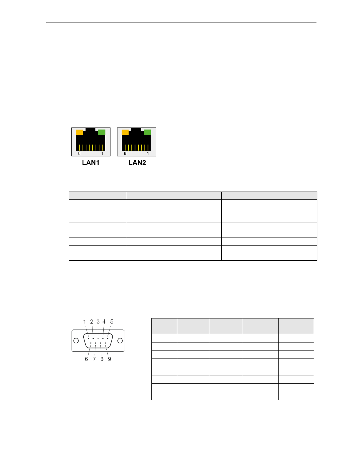
The 10/100/1000 Mbp s Ethernet LA N port uses 8-pin RJ45 conne c tor s . T he follo wing diagram shows the
pinouts for these ports.
The LED indicator
s on the
right top and right bottom corners glow a
solid green color when the cable is properly connected to a 100 Mbps
Ethernet network. The LED will flash on and off when Ethernet
packets are being transmitted or received.
The LED indicator
s on the
left top and left bottom corners glow a solid
yellow
color when the cable is properly connected to a 1000 Mbps
Ethernet network. The LED will flash on and off when Ethernet
packets are being transmitted or received.
Pin 10/100 Mbps 1000 Mbps
1 ETx+ TRD(0)+
2 ETx- TRD(0)3 ERx+ TRD(1)+
4 --- TRD(2)+
5 --- TRD(2)6 ERx- TRD(1)7 --- TRD(3)+
8 --- TRD(3)-
Connecting to a Serial Device
Use a serial cable to plug your serial device into the embedded computer’s serial port. Serial ports P1 to P4 have
male DB9 connectors and can be configured for RS-232, RS-422, or RS-485 communication by software. The
pin assignments are shown in the following table:
DB9 Male
Port
RS
-232/422/485 Pinouts
Pin RS
-232
RS
-422
RS
-485
(4
-wire)
RS
-485
(2
-wire)
1 DCD TxDA(
-)
TxDA(
-)
--- 2 RxD TxDB(+)
TxDB(+)
--- 3 TxD RxDB(+)
RxDB(+)
DataB(+)
4 DTR RxDA(
-)
RxDA(
-)
DataA(
-)
5 GND GND GND GND 6 DSR --- --- --- 7 RTS --- --- --- 8 CTS --- --- ---
The V2401 also includes an RS-232 connector on the front panel. It can connec t eight devic e s with a 68-pin
VHDC cable. This cable must be purchased separately. Simply connect one end of the connector to the V2401,
and connect the other end to eight serial devices.
Page 19

V2401/2402 HW User's Manual Hardware Connec tion Description
3-7
Installing a CompactFlash Card
The V2401/2402 embedded computers come with a CompactFlas h so cke t. To ins ert a Comp ac tFlash card,
follow these instructions:
1. Disconnect the V2401 /240 2 from its pow er sourc e .
2. The CompactFlash socke t is locate d on the lef t side of the front p ane l. U nscrew the Co mpac tFlash socket
cover.
3. There is a tenon/hook on the cover of the CF socket. Turn the CompactFlash card over and then insert the
CompactFlash card into the tenon/hook of the CF socket cover .
ATTENTION
Be careful of how you orient the CompactFlash card. You should tur n the CF card bottom side up, in orde r to
hook CF card into the CF socket cover.
4. Gently insert the Compac tFlash card into the CF socket, making sure that the card is oriented correctly.
Page 20

V2401/2402 HW User's Manual Hardware Connec tion Description
3-8
ATTENTION
The V2401/2402 embedded computer does not support the Compac tFla s h ho t swap and PnP (Plug and Play)
functions. It is necessary to remove power source firs t before ins e rting or removing the CompactFlash card.
Connecting a PS/2 Keyboard and Mouse
Your V2401/2402 embedded computers come with a PS/2 mini-DIN connector to connect to a PS/2 keyboard
and PS/2 mouse. This 6-pin mini-DIN connector has the pin assignme nts shown below.
PS/2 Connector Pin No. Signal Definition
1 PS/2 Keyboard Data
2 PS/2 Mouse Data
3 GND
4 VCC
5 PS/2 Keyboard Clock
6 PS/2 Mouse Clock
Use the Y-type cable to convert the mini-DIN connector into two 6-pin mini-DIN connectors to connect both a
PS/2 keyboard and PS/2 mouse at the same time. You may also use the USB ports to connect your USB-based
keyboard and mouse.
ATTENTION
Please note that without a Y
-type cable, the PS/2 connector on the V2401/2402 can only work with a PS/2
keyboard. A PS/2 mouse will not function when directly connected to the PS/2 connector on the V2401/2402
embedded comput ers.
Page 21

V2401/2402 HW User's Manual Hardware Connec tion Description
3-9
Connecting to the USB Device
The V2401/2402 c omes with 6 USB 2.0 hosts. Four are located on the front panel and the other two are on the
rear panel. The hosts can be used for an external flash disk or hard drive for storing large amounts of data. You
can also use these USB hosts to connect to a keyboard or a mouse.
DI/DO
The V2401/2402 comes with a 4-ch digital input and a 4-ch digital output through the terminal block. The pin
assignments and the wiring methods are shown below.
Page 22

V2401/2402 HW User's Manual Hardware Connec tion Description
3-10
Connecting to a VGA Monitor
The V2401/2402 comes with a D-Sub 15-pin female connector on the front panel to connect a VGA CRT monitor.
To ensure that the monitor image remains clear, be sure to tighten the monitor cable after connecting it to the
V2401/2402. The pin assignments of the VGA conne c tor are shown belo w .
DB15 Female Connector
Pin No. Signal Definition
1 Red
2 Green
3 Blue
4 NC
5 GND
6 GND
7 GND
8 GND
9 VCC
10 GND
11 NC
12 DDC2B Data
13 HSYNC
14 VSYNC
15
DDC2B Clock
Connecting to an LVDS Monitor
The V2401 also comes with a 26-pin LVDS connector on the front panel to connect a panel with an LVDS cable.
The pin assignments of the LVDS connector are shown below.
LVDS Female Connector
Pin No. Signal Definition
1 VDD_12V
2 GND
3 LVDS_CLK_N
4 LVDS_DAT_P3
5 GND
6 LVDS_DAT_N2
7 LVDS_DAT_P1
8 GND
9 LVDS_DAT_N0
10
VDD_12V
11 N/C
12 LVDS_CLK_P
13 GND
14 LVDS_DAT_N3
15 LVDS_DAT_P2
16 GND
17 LVDS_DAT_N1
18 LVDS_DAT_P0
19 VDD_5V
20
VDD_5V
21 VDD_3V3
22 VDD_3V3
23 GND
24 BKLT_EN
Page 23

V2401/2402 HW User's Manual Hardware Connec tion Description
3-11
Connecting to a DVI-I Monitor
The V2401/2402 computers come with a DVI-I connector that can connect to a DVI monitor. Use the cable to
connect one end to the DVI-I connector and the other end to the monitor. See the following tab l e for DVI-I
connector pin assignments.
DVI Connector Pin No. Signal Definition
1 T.M.D.S. D ata 2 2 T.M.D.S. D ata 2+
3 T.M.D.S. Data2/4 Shield
4 T.M.D.S. D ata 4 5 T.M.D.S. D ata 4 6 DDC Clock
7 DDC Data
8 Analog Vertical Sync
9 T.M.D.S. D ata 1 10 T.M.D.S. Data1+
11 T.M.D.S. Data1/3 Shield
12 T.M.D.S. Data313 T.M.D.S. Data3+
14 +5V Power
15 Ground (return for +5V, HSync, and
VSync)
16 Hot Plug Detect
17 T.M.D.S. Data018 T.M.D.S. Data0+
19
T.M.D.S. Data0/5 Shield
20 T.M.D.S. Data521 T.M.D.S. Data5+
22 T.M.D.S. Clock Shield
23 T.M.D.S. Clock+
24 T.M.D.S. ClockC1 Analog Red
C2 Analog Green
C3 Analog Blue
C4 Analog Horizontal Sync
C5 Analog Ground
(analog R, G, B return)
Connecting to a Sp eaker or a Headphone
The V2401/2402 comes with audio input and output interfaces for connecting a microphone and speaker or
headphones. See the following figure for details.
Page 24

V2401/2402 HW User's Manual Hardware Connec tion Description
3-12
Upgrading the Memory Module
The V2401/2402 embedded computers support one 200-pin DDR2 533 SODIMM module of up to 2GB. One
DDR2 SDRAM memory module is installed at the factory. To upgrade the DDR2 SDRAM memory module, follow
these instructions:
Disconnect the V2401/2402 from the power source.
Remove the eight screws on the front panel and two screws on the rear panel. Also, you need to remove the
screws on the display connectors, including VGA , DVI and LVDS. See the follo w ing f ig ure s for details .
When finished, pull up the back cover of the V2401/2402 computer .
Find the location of the memory module.
Page 25

V2401/2402 HW User's Manual Hardware Connec tion Description
3-13
Carefully remov e the module by clic king the clutches at both sides of the module, and then replace the new
module. Be sure to orient the module correctly.
When finished, replace the back cover of the computer.
Upgrade the DOM Module
The V2401/2402 has been pre-installed with a DOM to store the OS. To upgrade the DOM module, see the
following steps.
After taking off the back cover of the V2401/2402, find the loca tio n of the DO M module socke t.
Page 26
V2401/2402 HW User's Manual Hardware Connec tion Description
3-14
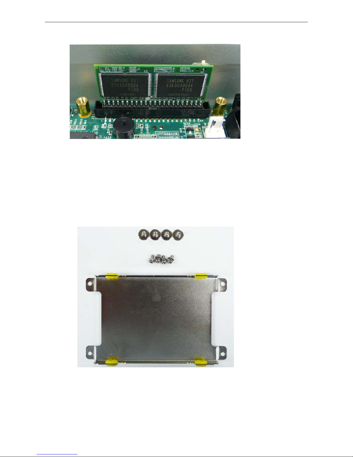
Remove the DOM module by pulling it up.
Insert the new DOM module; make sure it is firmly inserted.
Installing a SATA Hard Disk
The V2401/2402 embedded computers have one SATA connector for ins talling a SATA hard disk. To install a
2.5-inch SATA hard disk, follow these instruc tio ns .
1. Disconnect the V2401/2402 from its power so u rc e.
2. The V2401/2402 has an optional hard drive disk installation kit which must be purchased separate ly . I t
includes a hard drive disk bracket, four screws to attach the hard dr ive disk and ano the r four scr ews to
attach the bracket to the computer.
Page 27
V2401/2402 HW User's Manual Hardware Connec tion Description
3-15
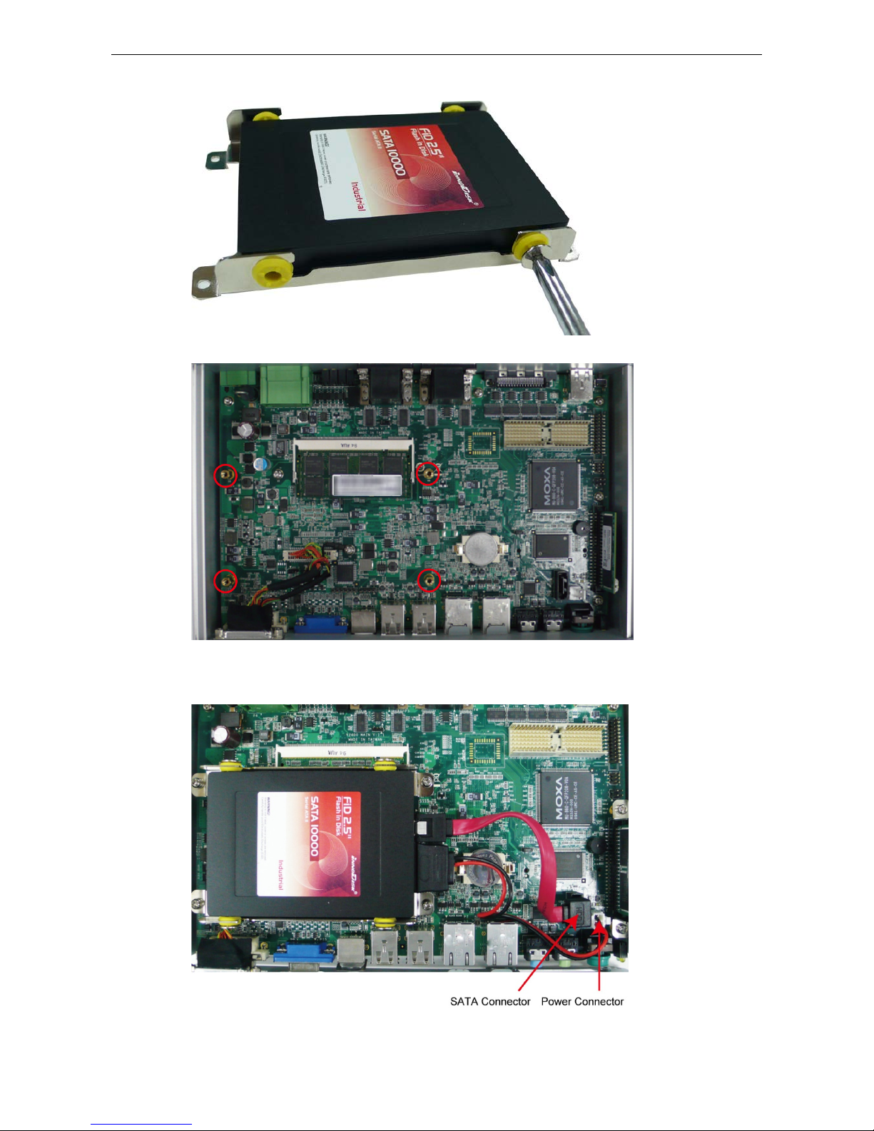
3. Place the hard drive disk on the bracket and use four scr ew to attach it.
4. When finished, place the br ack e t on the main board a nd fi nd the locati o n for attac hm e nt.
5. Make sure that four screws have been securely attached on the main board. Then use the SATA cable to
connect the hard drive disk to the SATA connector, and use the power cable to connec t to the power
connector.
6. When finished, replac e the b ack cover of the compute r .
Page 28

4
4. BIOS Setup
This chapter describes the BIOS settings of the V2401/2402 embedded computers. The BIOS is a set of
input/output control routines for peripherals. The BIOS is used to initialize basic peripherals and helps boot the
operating system before the operating system is loaded. The BIOS setup allows the user to modify the system
configurations of these basic input/output p e ripherals. All of the configurations will be stored in the battery
backed up CMOS RAM, which retainsthe system information after sys te m reboo ts or the pow er is remov ed.
The following topics are covered in this chapter :
Entering the BIOS Setup Utility
Modifying the BIOS Main Settings
Bas ic Co nfiguration
System Security
Advanced Setting s
Har d Disk Bo o t Prior ity
Advanced BIOS Features
CPU Features
Advanced Chipset Settings
Peripherals
OnChip IDE Device
Onboard Device
Super I/O Device
Power
ACPI Suspend Type
Soft-Off by PWR-BTTN
Hardware Monitor
CPU Warning T e mperature
War ning Beep
Load Defaults
Load System Default Settings
Load System Turbo Settings
Load CMOS from BIOS
S ave CMOS to BI OS
Exiting the BIOS Setup
Save & Exit Setup
Ex it Without Saving
Upgrading the BIOS
Page 29
V2401/2402 HW User's Manual BIOS Setup
4-2
Entering the BIOS Setup Utility
To enter the BIOS setup utility, press the “Del” key while the system is booting up. The main BIOS Setup screen
will appear.
A basic description of each function key is listed at the bottom of the screen. Refer to these descriptions to learn
how to scroll about the screen, how to select by pressing “Enter,” and how to use the other hot keys lis te d
below.
F1: General Help
F5: Previous Value
F6: Default Settings
F7: Turbo Setti ng s
F10: Save
ESC: Exit
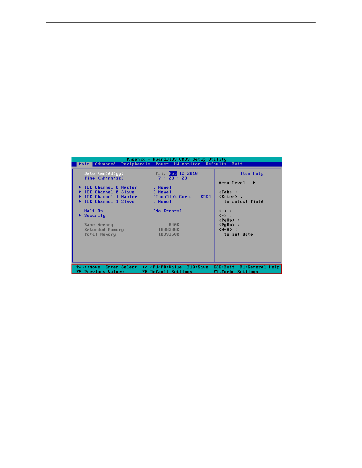
Modifying the BIOS Main Settings
Basic Configuration
After entering the BIOS Setup, or choosing the “Main” option, the BIOS main menu will be displayed. Use this
menu to check the basic system information such as memory and IDE hard drive. You can also use the menu
for configuring basic system parameters, such as date, time, hard drive, display, and syste m sec urity.
Page 30
V2401/2402 HW User's Manual BIOS Setup
4-3
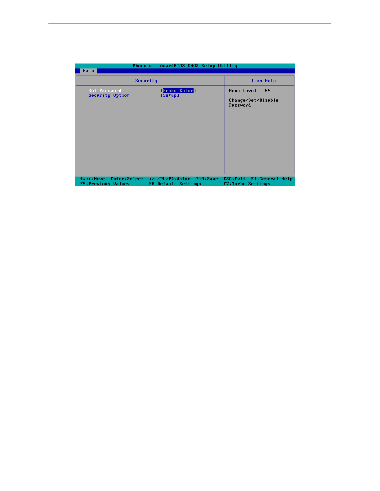
System Security
To set up system security, select the “Security” option under “Main” to bring up the fo llowing screen.
This menu includes two options: “Set Password” and “Security Option.”
When you select the Set Password option, a pop-up “Enter Password:” window will appear on the screen. The
password that you type will replace the password stored in the CMOS memory. You will be required to confirm
the new password. Just re-type the password and then press <Enter>. You may also press <Enter> to abort
the selection and not enter a password.
To clear an existing password, just press <Enter> when you are prompted to enter the password. A message
will show up confirming that the password will be disabled. Once the password is disabled, the system will boot
and you can enter the “BIOS Setup Menu” without entering a password.
Once a password has been set, you will be prompted to enter the password each time you enter Setup . This
prevents unauthorized persons from c hang i ng any part of your system configuration. In addition, when a
password setting is enabled, you can set up the BIOS to request a password each time the system is booted up.
The “Security Option” setting determines when a password prompt is required. If the “Security Option” is set
to “System,” the password must be entered both at boot up and when entering the BIOS Setup Menu. If the
password is set for “Setup,” the password prompt only occurs when you enter the “BIOS Setup Menu.”
Page 31
V2401/2402 HW User's Manual BIOS Setup
4-4
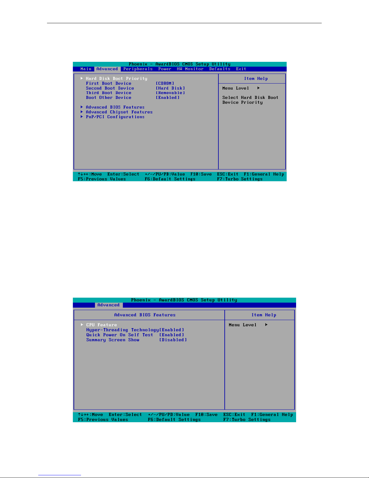
Advanced Settings
The “Advanced Features” screen will appear when choosing the “Advanced” item from the main menu.
Hard Disk Boot Priority
First/Second/Third Boot Device
This option allows users to select or change the device boot priori ty . You may set 3 level s of priority to
determine the boot up sequence for different bootable devices, such as a hard drive, CD-ROM, and removable
devices. Select the order in which devices will be searched in order to find a boot device. The available options
are “CDROM (default for first boot device),” “Removable” (default for third boot device), “Hard Disk” (default
for second boot device) and “Disabled.”
Advanced BIOS Features
When you select the “Advanced BIOS Features” option under the “Advanced” menu, the following configuration
menu will appear.
Page 32

V2401/2402 HW User's Manual BIOS Setup
4-5
CPU Features
C1E Function
This item allows you to configure the power-sav i ng mode when the C PU is in C1 status.
Options: Auto (default), Disabled
EIST Function
This item allows you to configure the power saving mode with the Enhanced Intel SpeedStep Technology. This
helps the system reduce the workload frequency and power consumption.
Options: Disabled (default), Enabled
Hyper-Threading Technology
This item allows you to enable or disable the hyper-threading function, which allows the system to handle more
than one thread at the same time.
Options: Enabled (default), Disable d
Quick Power On Self Test
This setting allows the system to skip certain tests while the system boots up. Enable this feature to speed up
the boot up process.
Options: Enabled (default), Disable d
Summary Screen Show
The summary screen displays system information, including CPU, memory, disk drive, and PCI devices. T he
default value is disabled. You may choose “Enabled” to disp lay this scr een when the sys tem is booting up .
Options: Disabled (default), Enable d
Advanced Chipset Settings
Page 33

V2401/2402 HW User's Manual BIOS Setup
4-6
On-chip Frame Buffer Size
This item determines the frame buffer size for the VGA function, and will sha r e the sys te m memory .
Options: 1 MB, 4 MB, 8 MB (default),
DVMT Mode
Sets the Dynamic Video Memory Technology oper ating mod e . Whe n set to “Fixed,” the graphics driver will
reserve a fixed portion of the system memory as graphics memory. When set to “DVMT,” the graphics driver
will dynamically allocate system memory as graphics memory, according to system and graphics requirements.
When set to “BOTH,” the graphics driver will allocate a fixed amount of memory as dedicated graphics memory,
as well as allow more system memory to be dynamically allocated betwe e n the grap hic s proce ssor and the
operating system.
Options: FIXED, DVMT (default), BOTH
DVMT/FIXED Memory Size
Sets the maximum amount of system memory that can be allocated as graphics memory.
Options: 64 MB, 128 MB (default).
Boot Display
This item allows you to choose which display interface w ill be show n when system is booting up. Due to the
display limitation, two displays at most can be shown when booting up. If you select the default option, VBIOS
Default", the displays that have been connected will be use d as the defaul t d ispla y s .
Options: VBIOS Default (default), VGA+DVI, VGA, DVI
LVDS Function
This item allows to enable or disable the LVDS functio n.
Options: Disabled (default), Enab le d
Panel Number
This item allows you to select the correct resolution ac cord i ng to your LVDS d ispla y .
ATTENTION
Note that you must select the correct resolution for your LVDS display based on your LVDS specifications, or it
will not be properly shown on your panel. When you encounter this prob l e m, take the follow ing s te ps:
1. Press the Inser t key after yo u hear the beep.
2. Restar t your comp ute r and press the Del key whil e the system is booting up.
3.
Reconfigure the VGA setting in the BIOS menu and select the correct resolution and data format for your
LVDS.
Page 34

V2401/2402 HW User's Manual BIOS Setup
4-7
Peripherals
OnChip IDE Device
On-Chip Channel 0 PCI IDE
This item allows you to enable or disable the Channel 0 onboard PCI dev ic e .
Options: Enabled (default), Disable d
IDE Channel 0 Master UDMA
This item allows you to configure UDMA mode for the device on IDE channel 0 Master.
Options: Disabled, Auto (default), UDMA33, UDMA66, UDMA100
IDE Channel 0 Slave UDMA
This item allows you to configure UDMA mode for the device on IDE channel 0 Slave..
Options: Disabled, Auto (default), UDMA33, UDMA66, UDMA100
Page 35

V2401/2402 HW User's Manual BIOS Setup
4-8
On-Chip Channel 1 PCI IDE
This item allows you to enable or disable the Channel 1 onboard PCI devic e .
Options: Enabled (default), Disable d
IDE Channel 1 Master UDMA
This item allows you to configure UDMA mode for the device on IDE channel 1 Master.
Options: Disabled, Auto (default), UDMA33, UDMA66, UDMA100
IDE Channel 1 Slave UDMA
This item allows you to configure UDMA mode for the device on IDE channel 1 Slave..
Options: Disabled, Auto (default), UDMA33, UDMA66, UDMA100
Onboard Device
Onboard Audio
This feature allows you to enable/disab le the aud io controller.
Options: Enabled (default), Disabled
Onboard LAN Boot ROM
Decide whether to invoke the boot ROM of the onboard LAN chip.
Options: Enabled, Disabled (default)
Page 36

V2401/2402 HW User's Manual BIOS Setup
4-9
Super I/O Device
Debug Port
This function allows you to enable/disable the deb ug port communication. The V2401/2402 computer will
automatically distribute the IRQ value for the debug port as the default value. If you wish to disable, select
Disabled. This port is only for engineers who are debugging programs.
Power on After Power Fail
This item allows you to configure the power on after power fail func tion.
Options: Off, On (default), Former-Sts
Power
The Power Setup Menu allows you to configure your system power-up/ power-down options.
Page 37

V2401/2402 HW User's Manual BIOS Setup
4-10
ACPI Suspend Type
This item allows you to set up the ACPI suspend type for power management functio n.
Option: S1 (POS), (default), S3 (STR)
Soft-Off by PWR-BTTN
This item determines the delay to stop the software when pushing the power b utto n.
Options: Instant-Off (def ault), Delay 4 Sec.
Hardware Monitor
This item helps monitor the status of the system, including CPU te mpe r a ture and the voltag e of the CPU,
SDRAM and battery.
CPU Warning Temperature
This item allows you to configure what temperature will trigger a high temperature warning.
Options: 80°C/176°F, 90°C/194°F (default), 100°C/212°F, Disabled
Warning Beep
This item allows you to enable/disable the warning beep.
Options: Disabled (default), Enable d
Page 38

V2401/2402 HW User's Manual BIOS Setup
4-11
Load Defaults
Load System Default Settings
Use this option to load system factory default settings instead of the current BIOS settings. This option is useful
for when the system is unstable. Users do not need to remember what settings were active before the system
fails.
Load System Turbo Settings
Use this option to load system optimized settings. If the system is not sta b le , plea se lo ad the system default
settings.
Load CMOS from BIOS
Use this option to load BIOS settings from flash ROM to CMOS.
Save CMOS to BIOS
Use this option to save the BIOS settings from the CMOS to flash ROM.
Exiting the BIOS Setup
To exit the BIOS setup utility, choose “Exit.” Pressing <ESC> will achieve the same result.
Page 39

V2401/2402 HW User's Manual BIOS Setup
4-12
Save & Exit Setup
Save all configuration changes to CMOS (memory ) and exit setup . A confir mation message will be displayed
before proceeding.
Exit Without Saving
Abandon all changes made during the current session and exit setup. A confirmation message will be displayed
before proceeding.
Upgrading the BIOS
This section describes how to upgrade the BIOS. However, please note that upgrading the BIOS involves high
risk of damage to your computer. We strongly recommend that you contact Moxa’s TS staff for assistance and
obtain all necessary tools and files before attempting to up gr ad e .
Step 1: Create a Bootable USB Disk.
We suggest you use the HP USB Disk Format Tool to create a bootable USB disk. You may download this tool
from the Internet. Search the Internet using the phrase “HP USB Disk Storage Form at Tool”, a nd then
download the tool from one of the listed websites.
You will also need to download the FreeDos system files kernel.sys and command.com from
http://www.freedos.org/kernel/.
1. Copy DOS system files kernel.sys and command.com to a specified directory (C:\FreeDOS in this
example).
2. Start the HP USB Disk Storage Format Tool and select the USB device that you want to use as a bootable
disk in the Device drop down box.
3. Select FAT in the File system drop down box.
4. Type the disk name in the Volume label field.
5. Check the option Create a DOS startup disk under format options.
6. Specify the directory of the system files (for example, C:\FreeDOS).
7. Click Start to forma t and create the USB disk.
Page 40

V2401/2402 HW User's Manual BIOS Setup
4-13
ATTENTION
We suggest you use a USB drive with under 2 GB in disk space, as larger USB drives may
not support the
FAT
file format and consequently fail to boot.
Step 2: Prepare the Upgrade Tool and BIOS Binary File.
You must use the BIOS upgrade installation file to upgrade the BIOS. You can send your request to Moxa's
technical support team at support@moxa.com
to get an updated version of the BIOS.
1. Get the BIOS upgrade installation file. The file name should have following format: 240010.s00.
2. Copy the f il e to the Bootable USB Disk.
3. Double click to extrac t the BIOS update installation file. The file includes a binary file in the for m
s210010.s00 and the upgrade utility named awdflash.exe.
Step 3: Set up the BIOS to Boot from the USB Disk.
1. Insert the USB disk.
2. Power on and press DEL to enter the BIOS Setup me nu.
3. Select Advanced Hard Disk Boot Priority and then press Enter.
4. From the Setup menu, use “↑” or “↓” to select the USB device.
5. Press “+” to move it up to the first priority, a nd pre ss “Esc ” to exit the setup menu.
6. Make sure the first boot device is Hard Disk. If it isn’t, press Enter to change it.
Page 41

V2401/2402 HW User's Manual BIOS Setup
4-14
7. Select Exit Save & Exit Setup and then press Enter.
8. Choose Y to save to the CMOS and then exit.
Step 4: Run awdflash.e xe to up grade the BIOS.
1. While in the BIOS Setup menu and before upgrading the BIOS, you may choose to save the old BIOS files
to a specific location. Type Y to do so, or N to begin the upgrade .
2. If the BIOS Setup is correct, it will restart and boot from the USB disk.
3. Run awdflash 240010.S00 from the command line to upgrad e the BIO S . Replace xxxxxxx.Sxx with the
BIOS binary file name discussed in Step 2.
4. Press F1 to reset the system after the bios upd ate is complete. The system should reboot at this time.
5. Please note that once the BIOS is suc c ess f ul ly upgr ade d , the def ault BIO S v alue s will be automatic all y
loaded. However, if you wish to re-configure the BIOS setting s , pr ess DEL while booting.
ATTENTION
Do
NOT switch off the power supply during the BIOS upgrade, as doing so may cause the system to crash.
Page 42

A
A. Regulatory Approval Statement
This device complies with part 15 of the FCC Rules. Operation is s ub jec t to the following
two conditions: (1) This device may not cause harmful inte rf e re nc e , and (2 ) this devi c e
must accept any interference received, including inte rference that may cause undesired
operation.
Class A: FCC Warning! This equipment has been tested and found to comply with the limits for a Class A digital
device, pursuant to part 15 of the FCC Rules. These limits are designed to provide reasonable protection
against harmful interference when the equip m e nt is operated in a commerc ia l e nvir o nment. This eq uipment
generates, uses, and can radiate radio frequency energy and, if not installed and used in accordance with the
instruction manual, may cause harmful interfere nc e to radio communic a tio ns . Operation of this equipment in
a residential area is likely to cause harmful interference in which case the user will be required to correct the
interference at his own expense.
European Community
Warning:
This is a class A product. In a domestic environment this produc t may cause radio interference in which case
the user may be required to take adequate measures.
 Loading...