

Moxa Technologies UC-8580-LX, UC-8580-T-CT-LX, UC-8580-T-LX Quick Installation Manual

P/N: 1802085800010
*1802085800010*
UC-8580 Series
Quick Installation Guide
Edition 1.0, July 2017
Technical Support Contact Information
www.moxa.com/support
Moxa Americas:
Toll
-free: 1-888-669-2872
Tel:
1-714-528-6777
Fax:
1-714-528-6778
Moxa China (Shanghai office):
Toll
-free: 800-820-5036
Tel:
+86-21-5258-9955
Fax:
+86-21-5258-5505
Moxa Europe:
Tel:
+49-89-3 70 03 99-0
Fax:
+49-89-3 70 03 99-99
Moxa Asia-Pacific:
Tel:
+886-2-8919-1230
Fax:
+886-2-8919-1231
Moxa India:
Tel:
+91-80-4172-9088
Fax:
+91-80-4132-1045
2017 Moxa Inc. All rights reserved.
- 2 -
Overview
The UC-8580 Series computer is a programmable communication-centric
gateway offering a rich variety of communication interfaces, such as
Ethernet, seri al , and digital inp uts/outputs. This EN 50155-compliant
computer is built for rail applications and comes with multiple wireless
WAN gateway interfaces making it an ideal choice for building wireless
communication infrastructure with 802.11b/g/n/ac and LTE data
collection and transmission.
Model Names and Package Checklist
The UC-8580 Series includes the following models:
Available Models
Operating Temperature
Conformal Coating
UC-8580-LX
-25 to 55°C (-13 to 131°F)
–
UC-8580-T-LX
-40 to 70°C (-40 to 158°F)
–
UC-8580-T-CT-LX
-40 to 70°C (-40 to 158°F)
The UC-8580 Series computer is shipped with the following items:
• UC-8580 Series computer
• CBL-4PINDB9F-100: 4-pin pin header to DB9 female console port
cable, 100 cm
• Quick insta l lation g uide (printed)
• Warranty card
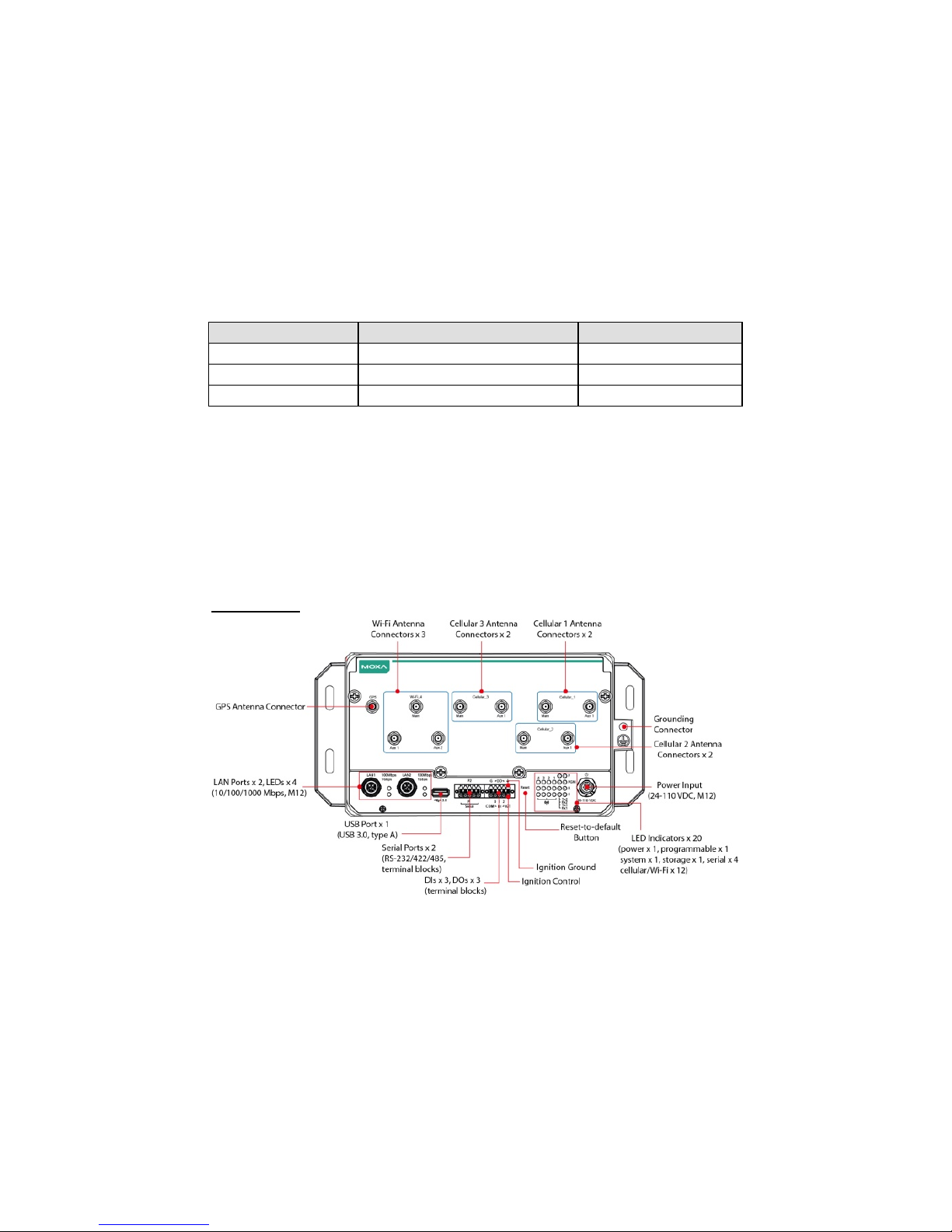
Appearance
Front View
- 3 -
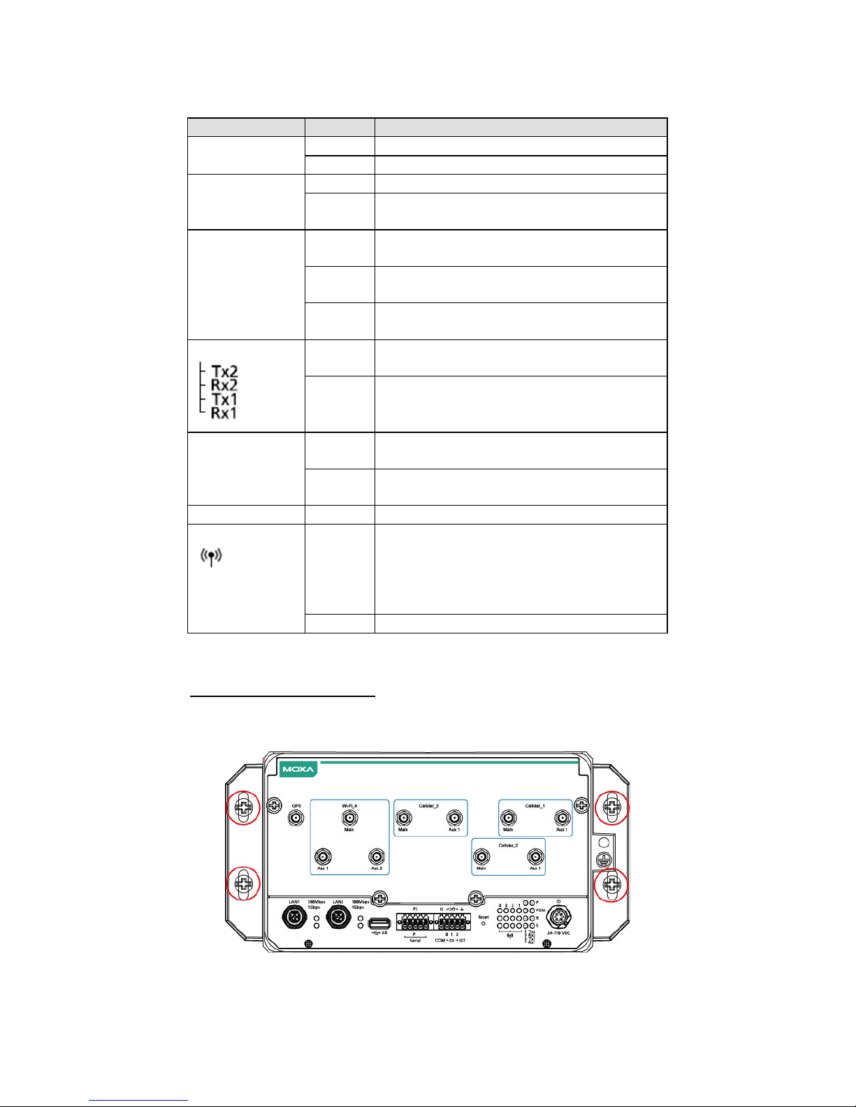
LED Indicato rs
Refer to the following table for the LED indicator definitions.
LED Name
Status
Function
P
Green
Power is on
Off
No power input or any other power error
R
Green
System is ready
Off
System is booting up, OS boot up failure, or
any other sys tem initialization error
Ethernet
(located next to
the Ethernet
ports)
Green
Steady On: 100 Mbps Ethernet link
Blinking: Data trans missio n is in progress
Yellow
Steady On: 1000 Mbps Ethernet link
Blinking: Data trans missio n is in progress
Off Data transmission speed at 10 Mbps or the
cable is not connected
Serial
Green
Tx: Data transmission is in progress
Rx: Receiving data
Off
No operation on the serial ports
S
Yellow
Blinking: The eMMC or mSATA module is
ready
Off
The eMMC or the mSATA module is not
accessible
PGM
Red
Programmable LED defined by user
Wireless
Green The number of glowing LEDs indicate the
wireless signal strength as follows:
3 Green: Excellent
2 Green: Good
1 Green: Poor
Off
No wireless signal
Installing the C omputer
Wall or Cabinet Mounting
Use two screws per sid e to mo u nt the UC-8580 computer on a wall o r in
a cabinet.
- 4 -
Wiring Requirements
Be sure to read and follow these common safety precauti ons before
proceeding with the installation of any electronic device:
• Use separate paths to route wiring for power and devices. If power
wiring and device wiring paths must cross, make sure the wires are
perpendicular at the intersection point.
NOTE
Do not run signal or communication wiring together with power
wiring in the same wire conduit. To avoid interference, wires with
different signal characteristics should be routed separately.
• Use the type of signal transmitted through a wire to determine which
wires should be kept separate. The rule of thumb is that wiring that
shares similar electrical characteristics can be bundled together.
• Keep input wiring and output wiring separate.
• It is advisable to label the wiring to all devices in the system.
ATTENTION
Safety First!
Be sure to disconnec t the power cord before installing and/or
wiring your
UC-8580 computer.
Wiring Caution!
Calculate the maximum possible current in each power wire and
common wire. Observ e all el ec t rical
codes dictating the
maximum current allowable for each wir e size. If the current go es
above the maximum ratings, the wiring could overheat, causing
serious damage to your equipment.
Temperature Caution!
Be careful when handling the unit. When the unit is plugged in,
the internal components generate heat, and consequently the
outer casing may feel hot to the touch.
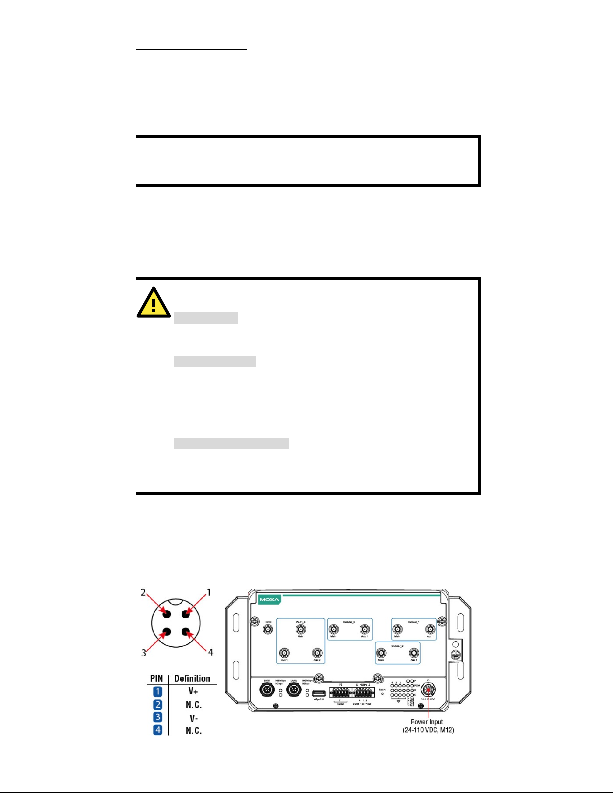
Connecting t h e Power
Connect the 24 to 110 VDC power line with M12 A-coded connector to the
UC-8580 computer. If the power is supplied properly, the “P” LED will
glow a solid green after a 25 to 30-second delay. The power i nput location
and pin definition are shown in the following figures:
 Loading...