

Page 1

UC-8540 Series Software User’s Manual
Edition 1.0, October 2018
www.moxa.com/product
© 2018 Moxa Inc. All rights reserved.
Page 2

UC-8540 Series Software User’s Manual
Moxa Americas
Toll
Tel:
Fax:
Moxa China (Shanghai office)
Toll
Tel:
Fax:
Moxa Europe
Tel:
Fax: +49-89-3 70 03 99-99
Moxa Asia
Tel:
Fax: +886-2-8919-1231
Moxa India
Tel:
Fax:
The software described in this manual is furnished under a license agreement and may be used only in accordance with
the terms of that agreement.
Copyright Notice
© 2018 Moxa Inc. All rights reserved.
Trademarks
The MOXA logo is a registered trademark of Moxa Inc.
All other trademarks or registered marks in this manual belong to their respective manufacturers.
Disclaimer
Information in this document is subject to change without notice and does not represent a commitment on the part of
Moxa.
Moxa provides this document as is, without warranty of any kind, either expressed or implied, including, but not limited
to, its particular purpose. Moxa reserves the right to make improvements and/or changes to this manual, or to the
products and/or the programs described in this manual, at any time.
Information provided in this manual is intended to be accurate and reliable. However, Moxa assumes no responsibility for
its use, or for any infringements on the rights of third parties that may result from its use.
This product might include unintentional technical or typographical errors. Changes are periodically made to the
information herein to correct such errors, and these changes are incorporated into new editions of the publication.
Technical Support Contact Information
www.moxa.com/support
-free: 1-888-669-2872
+1-714-528-6777
+1-714-528-6778
+49-89-3 70 03 99-0
-free: 800-820-5036
+86-21-5258-9955
+86-21-5258-5505
+886-2-8919-1230
-Pacific
+91-80-4172-9088
+91-80-4132-1045
Page 3

Table of Contents
1. Introduction ...................................................................................................................................... 1-1
2. Getting Started.................................................................................................................................. 2-1
Software Architecture .......................................................................................................................... 2-2
Software Packages .............................................................................................................................. 2-2
Connecting to the UC-8540 Computer ................................................................................................... 2-2
Using the Serial Console ............................................................................................................... 2-3
Using the SSH Console ................................................................................................................. 2-5
Sudo Mechanism ................................................................................................................................ 2-7
Booting Up the UC-8540 for the First Time ............................................................................................. 2-8
User Account Management ................................................................................................................... 2-8
Switching to the Root Account ...................................................................................................... 2-8
Creating and Deleting User Accounts ..................................................................................................... 2-9
Disabling the Default User Account ....................................................................................................... 2-9
Network Settings ................................................................................................................................ 2-9
Configuring Ethernet Interfaces ..................................................................................................... 2-9
System Administration ...................................................................................................................... 2-11
Querying the Firmware Version ................................................................................................... 2-11
Adjusting the Time .................................................................................................................... 2-11
Setting the Time Zone ............................................................................................................... 2-11
Determining Available Drive Space ...................................................................................................... 2-13
Enabling and Disabling Daemons ........................................................................................................ 2-13
Package Management........................................................................................................................ 2-14
Rebooting/Shutting Down the Computer .............................................................................................. 2-14
Updating the Firmware Using a USB Disk ............................................................................................. 2-15
3. Advanced Configuration of Peripherals ............................................................................................. 3-1
Serial Ports ........................................................................................................................................ 3-2
stty ........................................................................................................................................... 3-2
USB Port ............................................................................................................................................ 3-3
USB Automount .......................................................................................................................... 3-3
Restoring the Firmware to Factory Default Settings ................................................................................. 3-3
Using Cellular Modules ........................................................................................................................ 3-4
Cellular Signal Strength ............................................................................................................... 3-4
Cellular Management Utility .......................................................................................................... 3-4
Dial-Up Connections .................................................................................................................... 3-5
Disconnecting from a Dial-Up Network ........................................................................................... 3-6
Powering On/Off the Cellular Module .............................................................................................. 3-6
Configuring the Wireless LAN ............................................................................................................... 3-6
Wi-Fi Management Utility ............................................................................................................. 3-6
4. Programmer’s Guide ......................................................................................................................... 4-1
Introduction to the Linux Tool Chain...................................................................................................... 4-2
Native Compilation ...................................................................................................................... 4-2
Cross Compilation ....................................................................................................................... 4-2
Obtaining Help ............................................................................................................................ 4-4
Developing a Test Program—hello.c ...................................................................................................... 4-4
Compiling hello.c with Native Compilation ...................................................................................... 4-5
Compiling hello.c using Cross Compilation ...................................................................................... 4-5
Makefile Example ................................................................................................................................ 4-6
RTC (Real Time Clock) ......................................................................................................................... 4-6
WDT (Watch Dog Timer) ...................................................................................................................... 4-8
Cryptographic Hardware Accelerator ..................................................................................................... 4-8
LED Indicators .................................................................................................................................... 4-9
Power Ignition Function ..................................................................................................................... 4-10
5. Mobile Intelligent Routing Framework (MIRF) 2.0 ............................................................................ 5-1
Basic Configuration ............................................................................................................................. 5-3
Editing User Profiles ............................................................................................................................ 5-4
Using the Control Panel ....................................................................................................................... 5-5
Device Information ...................................................................................................................... 5-7
Editing the Hostname .................................................................................................................. 5-7
Editing the Device Name .............................................................................................................. 5-7
Checking the Software Version ...................................................................................................... 5-8
Checking the System Uptime ........................................................................................................ 5-8
Checking the System Memory Size ................................................................................................ 5-8
Maintenance ...................................................................................................................................... 5-9
Upgrading the Firmware ............................................................................................................... 5-9
Exporting the System Configuration File ....................................................................................... 5-10
Importing a System Configuration File ......................................................................................... 5-10
Rebooting the System ................................................................................................................ 5-10
Page 4

Exporting the System Log Files ................................................................................................... 5-11
Configuration Menu ........................................................................................................................... 5-11
Configuring MIRF 2.0 ................................................................................................................. 5-11
Configuring a Gateway ............................................................................................................... 5-12
Configuring Network Settings ...................................................................................................... 5-12
Configuring Ethernet Settings ..................................................................................................... 5-12
Configuring Wi-Fi Settings .......................................................................................................... 5-13
Configuring Cellular Settings ....................................................................................................... 5-19
Configuring Routing Client Settings.............................................................................................. 5-23
Configuring OpenVPN Client Settings ........................................................................................... 5-24
Configuring SSH Settings ........................................................................................................... 5-26
Configuring QoS Settings ........................................................................................................... 5-27
Configuring Load Balance Settings ............................................................................................... 5-28
Configuring SNMP Settings ......................................................................................................... 5-29
Configuring VRRP Settings .......................................................................................................... 5-30
Configuring Firewall Settings....................................................................................................... 5-33
Configuring System Settings ....................................................................................................... 5-36
Configuring Serial Settings ......................................................................................................... 5-37
Configuring the System Time ...................................................................................................... 5-38
Configuring Admin Settings ........................................................................................................ 5-39
Configuring GPS Settings ........................................................................................................... 5-40
Configuring Remote Control Settings ........................................................................................... 5-42
System Maintenance ......................................................................................................................... 5-43
Configuring Signal Tracker Settings ............................................................................................. 5-44
Managing User Accounts ............................................................................................................ 5-45
Creating a New Account ............................................................................................................. 5-45
Editing the Administrator Information .......................................................................................... 5-46
Updating User Account Information ............................................................................................. 5-47
Deleting a User Account ............................................................................................................. 5-48
Managing User Programs ............................................................................................................ 5-48
A. Using the General Debian Package .................................................................................................... A-1
NTP Client .......................................................................................................................................... A-2
Executing Scheduled Commands with cron............................................................................................. A-2
Updating System Time and RTC .................................................................................................... A-2
Log Processing using rsyslog ................................................................................................................ A-3
Rsyslog’s Configuration File .......................................................................................................... A-3
Using Selectors ........................................................................................................................... A-4
OpenSSL ........................................................................................................................................... A-4
Ciphers ...................................................................................................................................... A-5
Cryptographic Hash Functions ....................................................................................................... A-5
Public-Key Cryptography .............................................................................................................. A-5
SFTP ................................................................................................................................................. A-5
DNS .................................................................................................................................................. A-6
/etc/hosts .................................................................................................................................. A-6
/etc/resolv.conf ........................................................................................................................... A-7
/etc/nsswitch.conf ....................................................................................................................... A-7
iptables ............................................................................................................................................. A-7
Observing and Erasing Chain Rules ................................................................................................ A-9
Defining a Policy for Chain Rules ................................................................................................... A-9
Appending or Deleting Rules ....................................................................................................... A-10
NAT ................................................................................................................................................ A-10
NAT Example ............................................................................................................................ A-11
Enabling NAT at Bootup ............................................................................................................. A-11
rsync............................................................................................................................................... A-12
Using rsync for External Backups ................................................................................................. A-12
Automating rsync Backups ......................................................................................................... A-12
NFS (Network File System) ................................................................................................................ A-13
Setting Up the UC-8540 Computer as an NFS Client ...................................................................... A-13
SNMP .............................................................................................................................................. A-13
OpenVPN ......................................................................................................................................... A-15
Static-Key VPN .......................................................................................................................... A-15
Package Management........................................................................................................................ A-16
apt-get .................................................................................................................................... A-16
apt-cache ................................................................................................................................. A-16
Listing All Available Packages ...................................................................................................... A-16
Finding the Package Name and Software Description ..................................................................... A-16
Checking Package Information .................................................................................................... A-17
Checking Dependencies for Specific Packages ............................................................................... A-17
Checking the Cache Statistics ..................................................................................................... A-17
Updating System Packages ......................................................................................................... A-17
Installing or Upgrading Specific Packages ..................................................................................... A-17
Upgrading All Software Packages ................................................................................................. A-17
Page 5

Installing Multiple Packages ........................................................................................................ A-17
Installing Packages Without Upgrading ......................................................................................... A-17
Upgrading Specific Packages ....................................................................................................... A-18
Installing Specific Package Version .............................................................................................. A-18
Removing Packages ................................................................................................................... A-18
Completely Removing Packages .................................................................................................. A-18
Cleaning Up Disk Space.............................................................................................................. A-18
Downloading Only the Source Code of a Package ........................................................................... A-18
Downloading and Unpacking a Package ........................................................................................ A-18
Downloading, Unpacking, and Compiling a Package ....................................................................... A-18
Download a Package Without Installing the Package ...................................................................... A-19
Checking the Change Log of a Package ........................................................................................ A-19
Checking Broken Dependencies ................................................................................................... A-19
Searching and Building Dependencies .......................................................................................... A-19
Cleaning Apt-Get Cache ............................................................................................................. A-19
Removing Installed Packages ...................................................................................................... A-19
B. Firmware Upgrade ............................................................................................................................ B-1
Overview ........................................................................................................................................... B-2
A. Connecting to the UC-8540 Computer ........................................................................................ B-2
B. Download and Launch the TFTP Program .................................................................................... B-2
C. Downloading and Upgrading the Firmware Through the Serial Port ................................................ B-3
Page 6

1
1. Introduction
Thank you for purchasing Moxa’s UC-8540 Series Arm-based computer. This is the software operation and
programming manual for the Linux model of the UC-8540 computer and covers the use of Linux functions with
examples on how to program the UC-8540. In addition, detailed description of the various basic and advanced
functions of the Mobile Intelligent Routing Framework (MIRF) 2.0 tool are provided for use in rail applications.
Linux is an open source, scalable operating system that helps you build a wide range of innovative, small
footprint devices. Software written for desktop PCs can be easily ported to the embedded computer with a GNU
cross compiler and minimum source code modifications. A typical Linux-based device is designed for a specific
use, and is often not connected to other computers. In some cases, a number of such devices could be
connected to a centralized, front-end host. Examples include enterprise tools such as industrial controllers and
communications hubs.
Moxa's MIRF is an open-platform, multiple-WAN management tool that helps provide unbeatable wireless
service for train passengers as the train travels through different regions.
The wireless-enablement of the UC-8540 computer also makes it the most suitable choice for Industrial IoT
applications.
Page 7

2
2. Getting Started
In this chapter, we describe how to configure the basic settings in your UC-8540 computer.
The following topics are covered in this chapter:
Software Architecture
Software Packages
Connecting to the UC-8540 Computer
Using the Serial Console
Using the SSH Console
Sudo Mechanism
Booting Up the UC-8540 for the First Time
User Account Management
Switching to the Root Account
Creating and Deleting User Accounts
Disabling the Default User Account
Network Settings
Configuring Ethernet Interfaces
System Administration
Querying the Firmware Version
Adjusting the Time
Setting the Time Zone
Determining Available Drive Space
Enabling and Disabling Daemons
Package Management
Rebooting/Shutting Down the Computer
Updating the Firmware Using a USB Disk
Page 8
UC-8540 Series Software UM Getting Started
2-2
1
Linux kernel
W95 FAT32
32 MB
NOTE
Click on the following lin
https://wiki.debian.org/Ext4
https://ext4.wiki.kernel.org/index.php/Ext4_Howto
Software Architecture
The Linux operating system that is preinstalled on the UC-8540 computer follows standard Linux architecture,
making it easy to run any program that follows the POSIX standard. This computer uses the Debian ARM 8 so
that users can enjoy the full range of Debian software, and benefit from its strong community of developers and
shared documentation. With Debian ARM, the UC-8540 computer supports both native and cross compilation,
making programming on the computer easier and more straightforward.
The UC-8540 computer image is partitioned into Linux kernel, backup root file system, and root file system.
Refer to the following image partition table for details:
Partition System Content Partition Format Partition Size
2 Backup root file system EXT4 128 MB
3 Root file system EXT4 Rest of the capacity
The default file system format of the UC-8540 computer is EXT4, which is a journaling file system for Linux,
developed as the successor to EXT3. A journaling file system keeps track of the changes before committing
them to the main file system. In the event of a system crash or power failure, journaling file systems are
quicker at bringing back the computer online and less likely to get corrupted.
ks for more information on EXT4:
Software Packages
Most of the software packages come from the Debian community, whereas the unique features of the UC-8540
computer, such as the cellular and wireless connections, are supported by Moxa. Refer to Appendix A for
software packages installed by default and the Package Management section for information on managing the
software packages installed on your UC-8540 computer.
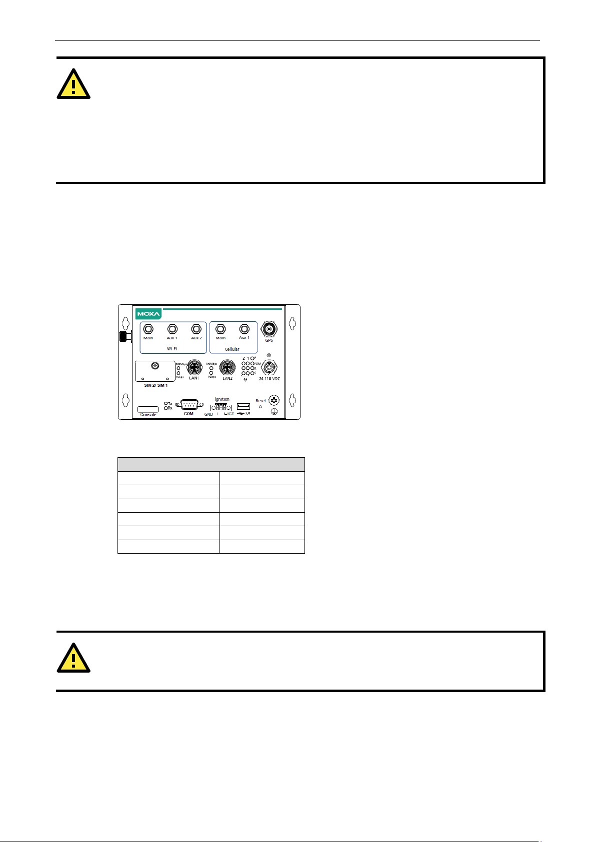
Connecting to the UC-8540 Computer
You will need access to a notebook computer or a PC to connect to the UC-8540 computer and log on to the
command line interface. There are two ways to connect to the UC-8540 computer: through a serial console
cable or through an Ethernet cable. Refer to the UC-8540 Series Hardware User’s Manual for instructions to set
up the physical connections for your computer.
The default login username and password are:
Username: moxa
Password: moxa
The username and password are the same for all serial console and SSH remote log in actions. The
account login is disabled until you manually create a password for the account. The user
group, which means that this user can use the
details on using the
sudo command are available in the Sudo Mechanism section.
root
moxa is in the sudo
sudo command to run system-level commands. Additional
Page 9
UC-8540 Series Software UM Getting Started
2-3
ATTENTION
For security reasons, we recommend that you disable the default user account
complete
If you want to change the settings manually via the SSH console or serial console, turn off MIRF 2.0. If not, the
settings may be restored to MIRF 2.0 settings.
Th
turn on:
turn off: mx-tp-ctl -e 0
Flow Control
None
WARNING
DO NOT apply these steps to the
to
connect to the
and create new user accounts as per your requirement.
e commands to change MIRF 2.0 state are as follows:
mx-tp-ctl -e 1
Using the Serial Console
This method is particularly useful when you are using the UC-8540 computer for the first time. The signal is
transmitted over a direct serial connection without using an IP address.
To connect to the UC-8540 computer using a serial console port, do the following:
1. Open the console port cover on the front panel and connect one end of the cable to it
after the initial set up is
2. Connect the other end of the serial console cable to your PC.
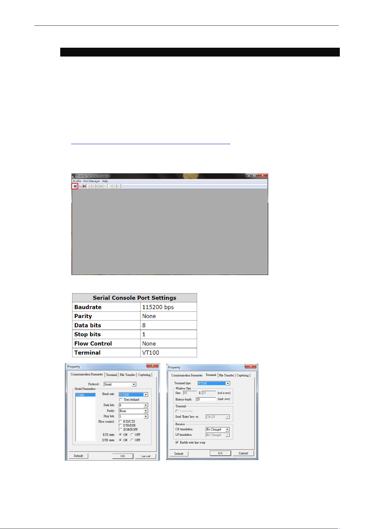
3. Configure your PC’s terminal software with the following settings:
The procedure to use the terminal software to connect to the UC-8540 computer in a Linux environment and in
a Windows environment is described in the following two sections:
Linux Users
Serial Console Port Settings
Baudrate 115200 bps
Parity None
Data bits 8
Stop bits 1
Terminal VT100
UC-8540 computer. These steps apply only to the Linux PC that you use
UC-8540 computer.
Page 10
UC-8540 Series Software UM Getting Started
2-4
user@PC1:~# yum -y install minicom
user@PC2:~# apt-get install minicom
user@PC1:~# minicom –s
NOTE
You need to know which device node is connected to the
user@PC1:~# minicom
+---------------------------------------------------------------+
+---------------------------------------+
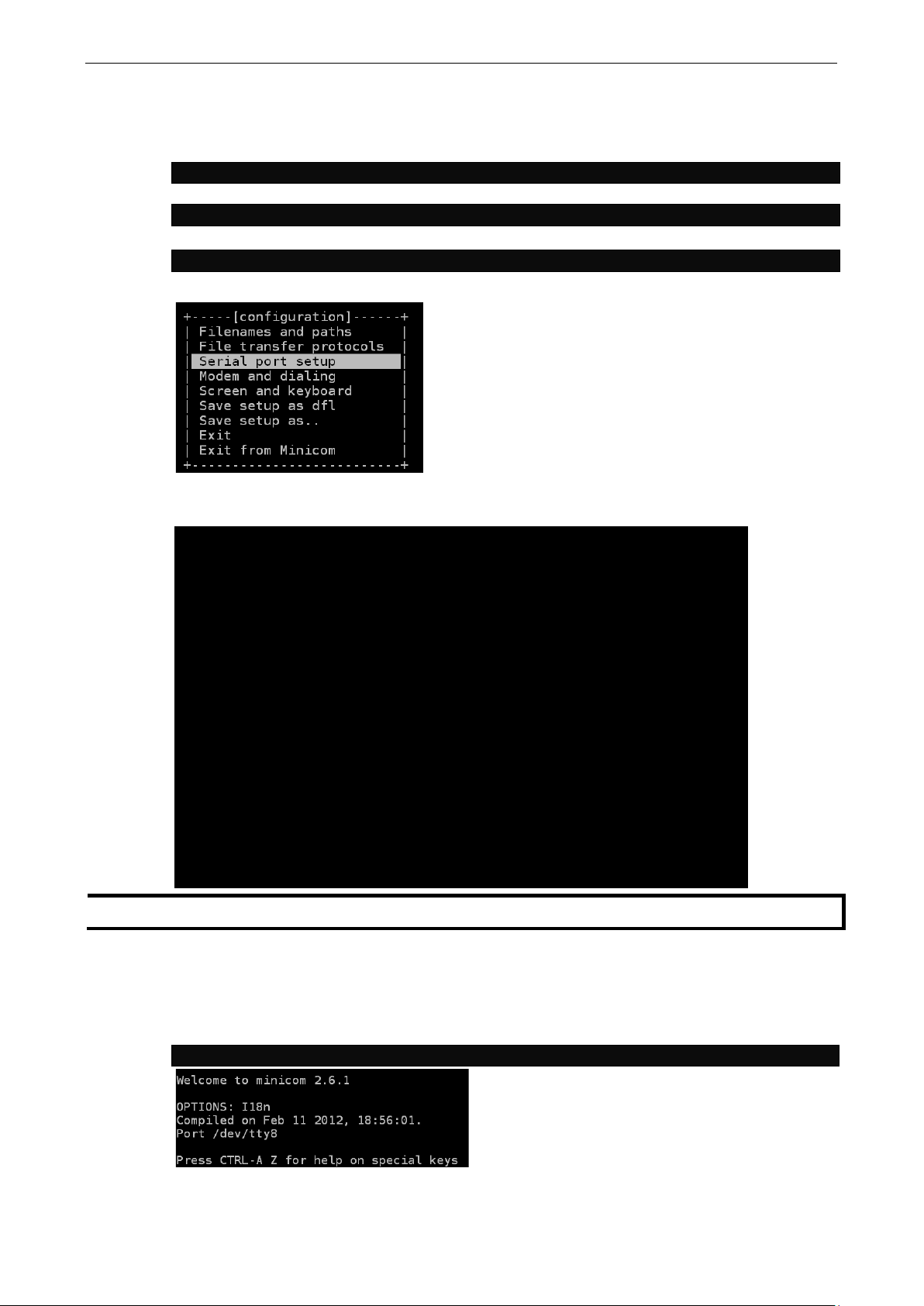
Take the following steps to connect to the UC-8540 computer from your Linux PC.
1. Install minicom from the package repository of your operating system.
For Centos and Fedora, run the following command:
For Ubuntu and Debian, run the following command:
2. Use the minicom –s command to enter the configuration menu and set up the serial port settings.
3. Select Serial port setup.
4. Select A to change the serial device setting.
| A – Serial Device : /dev/ttyM0
| B – Lockfile Location : /var/lock
| C – Callin Program :
| D – Callout Program :
| E – Bps/Par/Bits : 115200 8N1
| F – Hardware Flow Control : Yes
| G – Software Flow Control : No
|
| Change which setting?
+---------------------------------------------------------------+
| Screen and keyboard |
| Save setup as dfl |
| Save setup as.. |
| Exit |
| Exit from Minicom |
5. Select E to configure the port settings according to the Serial Console Port Settings table provided
above.
6. Select Save setup as dfl (from the main configuration menu) to use default values.
7. Select Exit from minicom (from the configuration menu) to leave the configuration menu.
8. Run the minicom tool after completing the abovementioned configuration settings.
UC-8540 computer to configure this setting.
Page 11
UC-8540 Series Software UM Getting Started
2-5
WARNING
DO NOT apply these steps to the
connect to the
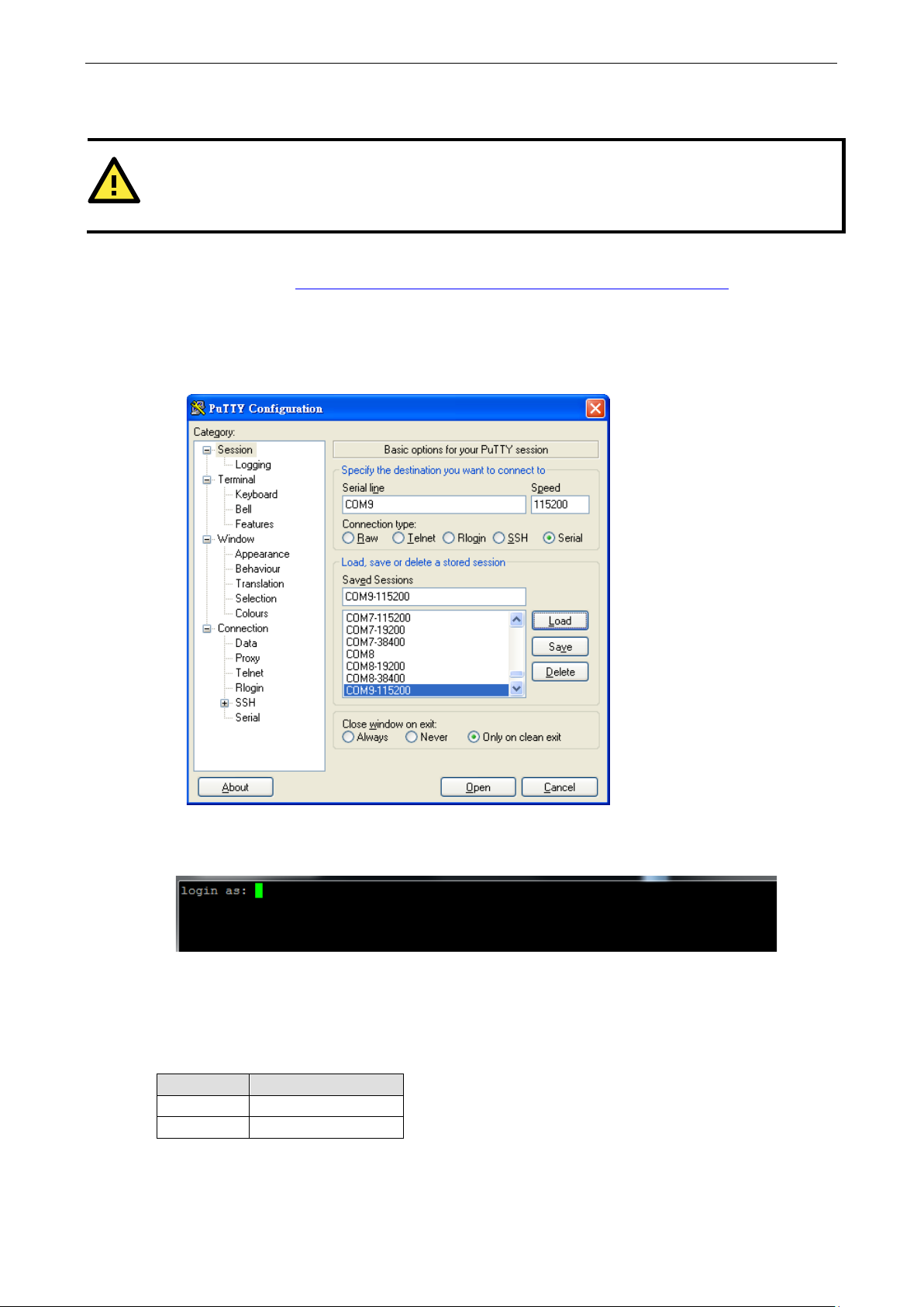
Windows Users
Take the following steps to connect to the UC-8540 computer from your Windows PC:
1. Download PuTTY (http://www.chiark.greenend.org.uk/~sgtatham/putty/download.html
and telnet client for Windows.
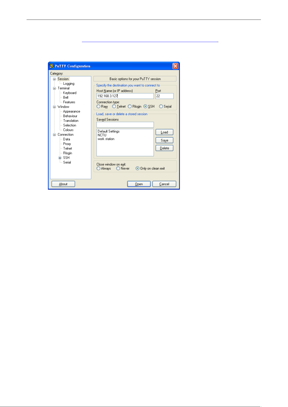
2. Run the PuTTY application (putty.exe) on the Windows PC.
3. Enter the details of the serial connection in the configuration window.
The figure below shows an example of the configuration that is required:
UC-8540 computer.
UC-8540 computer. These steps are for the Windows PC that you use to
), the free SSH
4. Click Open.
5. Type in the
UC-8540 computer.
Using the SSH Console
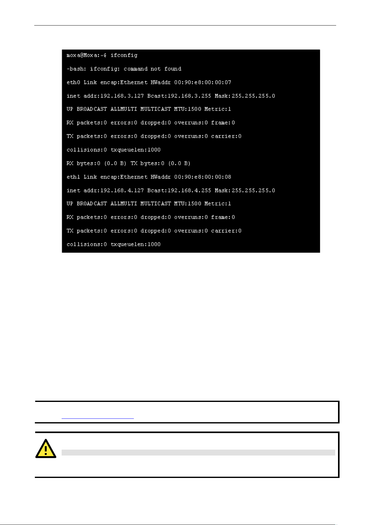
The UC-8540 computer supports SSH connections over an Ethernet network. Use the following default IP
addresses to connect to the UC-8540 computer:
Port Default IP
LAN 1 192.168.3.127
LAN 2 192.168.4.127
username and password in the console that opens up to establish a serial connection with the
Page 12
UC-8540 Series Software UM Getting Started
2-6
NOTE
Do NOT apply these steps to the
that
you us
user@PC1:~ ssh moxa@192.168.3.127
The authenticity of host ‘192.168.3.127 (192.168.4.127)’ can’t be established.
Are you sure you want to continue connection (yes/no)?
ATTENTION
Rekey SSHD regularl
In order to secure your system, we suggest doing a regular SSH
cd /etc/ssh
sudo ssh-keygen -t ecdsa –f /etc/ssh/ssh_host_ecdsa_key
When prompted for a passphrase, leave
Restart SSH as follows:
moxa@Moxa:~$ sudo /etc/init.d/ssh restart
For more information about S
https://wiki.debian.org/SSH
NOTE
Do NOT apply these steps to the
connect to the
Linux Users
e to connect to the UC-8540 computer.
Use the ssh command to access the UC-8540 computer’s LAN1 port from a Linux computer.
Type yes to complete the connection.
UC-8540 Computer. The instructions in this section are for the Linux PC
RSA key fingerprint is 8b:ee:ff:84:41:25:fc:cd:2a:f2:92:8f:cb:1f:6b:2f.
yes_
sudo rm –rf
ssh_host_dsa_key ssh_host_ecdsa_key ssh_host_rsa_key
ssh_host_dsa_key.pub ssh_host_ecdsa_key.pub ssh_host_rsa_key.pub
sudo ssh-keygen -t rsa -f /etc/ssh/ssh_host_rsa_key
sudo ssh-keygen -t dsa -f /etc/ssh/ssh_host_dsa_key
y
-rekey as shown in the following steps.
SH, refer to the following link:
Windows Users
UC-8540 computer.
UC-8540 computer. These steps are for the Windows PC that you use to
the passphrase empty and press Enter.
Page 13
UC-8540 Series Software UM Getting Started
2-7
Take the following steps from your Windows PC.
Click on the link, http://www.chiark.greenend.org.uk/~sgtatham/putty/download.html
(free software) to set up an SSH console for the UC-8540 computer in a Windows environment. The following
figure shows an example of the configuration that is required:
to download PuTTY
In the console that opens up, type in the
UC-8540 computer.
Sudo Mechanism
In the UC-8540-LX, the root account login is disabled to ensure a higher level of security. Sudo is a program
designed to let system administrators allow some users to execute some commands as root (or another user).
The basic philosophy is to give as few root privileges as possible to users to enable them to get their work done.
Using sudo is better (safer) than opening a session as root for a number of reasons, including:
• Nobody needs to know the root password (
can be granted to individual users temporarily, and then taken away without the need for a password
change.
• It is easy to run only the commands that require special privileges via
as an unprivileged user, which reduces the damage that mistakes can cause.
username and password to establish an SSH connection with the
sudo prompts for the current user's password). Extra privileges
sudo; the rest of the time, you work
Page 14
UC-8540 Series Software UM Getting Started
2-8
NOTE
Click the following link for more information on
sudo
https://wiki.debian.org/sudo
ATTENTION
You m
root account.
You must use
Note
The code below demonstrates that some system-level commands are not available to the user moxa.
Booting Up the UC-8540 for the First Time
We suggest using the serial console when you log in for the first time. Once you have connected the UC-8540
computer to a PC, power on the UC-8540. The computer will start the boot-up process immediately. The power
LED will light up first, followed by the ready LED. The serial console will display messages that indicate the
status of the boot-up process. When the computer boots-up for the first time, the root file system is resized and
initialized.
User Account Management
Switching to the Root Account
You can switch to the root user account using the sudo -i (or sudo su) command. For security reasons, do
not operate the “a
ll” command from the root account.
the
command:
ight get a permission denied message when you use pipe or redirect behavior with a non-
‘sudo su –c’ to run the command instead of using >, <, >>, <<, etc.
: The single quotes around the full command are required.
Page 15
UC-8540 Series Software UM Getting Started
2-9
moxa@Moxa:~# sudo useradd -m -G sudo -s /bin/bash test1
moxa@Moxa:~# sudo passwd test1
passwd: password updated successfully
moxa@Moxa:# sudo userdel test1
ATTENTION
You should first create a user account before you disable the default account.
root@Moxa:# passwd –l moxa
root@Moxa:# passwd –u moxa
moxa@Moxa:~$ cd /etc/network/
moxa@Moxa:/etc/network/~$
Creating and Deleting User Accounts
You can use the commands useradd and userdel to create and delete user accounts. Refer to the main page
of these commands to set relevant access privileges for the account. The following example shows how you can
create a user,
/home/test1.
To change the password of test1, use the passwd command and enter the new password twice to confirm the
change as shown below:
Enter new UNIX password:
Retype new UNIX password:
To delete the test1 user, use the userdel command as follows:
test1 in the sudo group. The default login shell for the user is bash and the home directory is
Disabling the Default User Account
Use the passwd command to lock the default user account so the user, moxa cannot log in.
To unlock the user account moxa, use the following command:
Network Settings
Configuring Ethernet Interfaces
After the first login, you can configure the UC-8540 computer’s network settings to better fit your application.
A serial console makes it more convenient for you to manipulate the network interface settings, which can help
you to avoid reconnections, when compared to an SSH login.
Modifying Network Settings via the Serial Console
In this section, we use the serial console to configure the UC-8540 computer’s network settings. Follow the
instructions given in the Connecting to the UC-8540 Computer section to access the console utility of the target
UC-8540 computer via the serial console port, and then type
directory path.
Moxa:~# cd /etc/network to change the
Type Moxa:~# sudo vi interfaces to edit the network configuration file with the vi editor. You can
configure the UC-8540 computer’s Ethernet ports to use either
static or dynamic (DHCP) IP addresses.
Page 16
UC-8540 Series Software UM Getting Started
2-10
ATTENTION
After changing
Example:
ifdown eth0 (turn off eth0)
ifup eth0 (turn on eth0).
iface eth0 inet static
broadcast 192.168.3.255
iface eth0 inet dhcp
# embedded ethernet LAN1
iface eth0 inet dhcp
# interfaces(5) file used by ifup(8) and ifdown(8)
Setting a Static IP Address
To set a static IP address for the UC-8540 computer, use the iface command to modify the address,
network, netmask, and broadcast parameters of the Ethernet interface.
auto eth0 eth1 lo
iface lo inet loopback
# embedded ethernet LAN1
iface eth0 inet static
address 192.168.3.127
network 192.168.3.0
netmask 255.255.255.0
broadcast 192.168.3.255
# embedded ethernet LAN2
iface eth1 inet static
address 192.168.4.127
network 192.168.4.0
netmask 255.255.255.0
broadcast 192.168.4.255~
the IP configuration, restart the Ethernet interface.
Setting a Dynamic IP Address
To configure one or both LAN ports to request an IP address dynamically, use the dhcp option in place of the
static option in the iface command as follows:
Default Setting for LAN1 Dynamic Setting using DHCP
address 192.168.3.127
network: 192.168.3.0
netmask 255.255.255.0
Page 17

UC-8540 Series Software UM Getting Started
2-11
moxa@Moxa:~$ kversion
UC-8540-LX version 1.1
moxa@Moxa:~$ kversion -a
UC-8540-LX version 1.1 Build 18090615
moxa@Moxa:~$ sudo date 071123192014
Mon Jul 11 23:19:00 UTC 2014
moxa@Moxa:~$ sudo hwclock –w
Fri 11 Jul 2014 11:19:38 PM UTC -1.006862 seconds
NOTE
Click the following links for more information on date and time:
https://www.debian.org/doc/manuals/system
https://wiki.debian.org/DateTime
System Administration
Querying the Firmware Version
To check the UC-8540 computer’s firmware version, type:
Add the –a option to the command to view the build number:
Adjusting the Time
The UC-8540 computer has two time settings. One is the system time, and the other is the RTC (Real-Time
Clock) time maintained by the UC-8540 Series hardware. Use the
system time or set a new system time. Use the
RTC time.
#hwclock command to query the current RTC time or set a new
#date command to query the current
Use the date MMDDhhmmYYYY command to set the system time:
MM = Month
DD = Date
hhmm = hour and minute
Use the following command to set the RTC time using the system time:
moxa@Moxa:~$ sudo hwclock
Setting the Time Zone
There are two ways to configure the Moxa embedded computer’s time zone. One is using the TZ variable. The
other is using /etc/localtime file.
-administrator/ch-sysadmin-time.html
Using the TZ Variable
The format of the TZ environment variable format looks like this:
TZ=<Value>HH[:MM[:SS]][daylight[HH[:MM[:SS]]][,start date[/starttime], enddate[/endtime]]]
Here are some possible TZ settings for the North American Eastern time zone:
1. TZ=EST5EDT
2. TZ=EST0EDT
3. TZ=EST0
In the first case, the reference time is GMT and the stored time values are correct worldwide. A simple change
of the TZ variable can print the local time correctly in any time zone.
Page 18

UC-8540 Series Software UM Getting Started
2-12
moxa@Moxa:~$ TZ= EST5EDT
moxa@Moxa:~$ export TZ
+9
JST
Japan
-7
MST
Mountain Standard Time
In the second case, the reference time is Eastern Standard Time and the only conversion performed is for
Daylight Saving Time. Therefore, there is no need to adjust the hardware clock for Daylight Saving Time twice
per year.
In the third case, the reference time is always the time reported. You can use this option if the hardware clock
on your machine automatically adjusts the Daylight Saving Time or you would like to manually adjust the
hardware time twice a year.
You must include the TZ setting in the
restart the computer.
The following table lists other possible values for the TZ environment variable:
Hours From Greenwich Mean Time (GMT) Value Description
0 GMT Greenwich Mean Time
+1 ECT European Central Time
+2 EET European Eastern Time
+2 ART
+3 EAT Saudi Arabia
+3.5 MET Iran
+4 NET
+5 PLT West Asia
+5.5 IST India
+6 BST Central Asia
+7 VST Bangkok
+8 CTT China
/etc/rc.local file. The timezone setting will be activated when you
+9.5 ACT Central Australia
+10 AET Eastern Australia
+11 SST Central Pacific
+12 NST New Zealand
-11 MIT Samoa
-10 HST Hawaii
-9 AST Alaska
-8 PST Pacific Standard Time
-7 PNT Arizona
-6 CST Central Standard Time
-5 EST Eastern Standard Time
-5 IET Indiana East
-4 PRT Atlantic Standard Time
-3.5 CNT Newfoundland
-3 AGT Eastern South America
-3 BET Eastern South America
-1 CAT Azores
Using the /etc/localtime File
The local timezone information is stored in the /etc/localtime file and is used by the GNU Library for C
(glibc) if no value has been set for the TZ environment variable. This file is either a copy of the
/usr/share/zoneinfo/ file or a symbolic link to it. You should find a suitable timezone information file and
write over the original local time file in the UC-8540 computer.
Page 19

UC-8540 Series Software UM Getting Started
2-13
moxa@Moxa:~$ sudo systemctl enable snmpd
moxa@Moxa:~$ sudo systemctl disable snmpd
### BEGIN INIT INFO
YOUR SCRIPT
moxa@Moxa:~$ sudo /etc/init.d/snmpd start
moxa@Moxa:~$ sudo /etc/init.d/snmpd stop
Determining Available Drive Space
To determine the amount of available drive space, use the df command with the –h tag. The system will return
the amount of drive space broken down by file system. Here is an example:
moxa@Moxa:~$ df -h
Filesystem Size Used Avail Use% Mounted on
/dev/root 3.3G 600M 2.6G 19% /
devtmpfs 505M 0 505M 0% /dev
tmpfs 505M 0 505M 0% /dev/shm
tmpfs 505M 6.8M 499M 2% /run
tmpfs 5.0M 0 5.0M 0% /run/lock
tmpfs 505M 0 505M 0% /sys/fs/cgroup
Enabling and Disabling Daemons
By default, only the following daemons are enabled in the UC-8540 computer:
sshd Secure shell server daemon
You can use the
example shows how to add the SNMP daemon to the current run level.
The SNMP daemon will not get activated in the current boot session, but will be running in the background from
the next boot session.
To disable the SNMP daemon, use the following command:
You can also write your own script to start and stop a daemon during the system “init” stage:
systemctl command to manage which services will run in the background. The following
# Provides: scriptname
# Required-Start: $remote_fs $syslog
# Required-Stop: $remote_fs $syslog
# Default-Start: 2 3 4 5
# Default-Stop: 0 1 6
# Short-Description: Start daemon at boot time
# Description: Enable service provided by daemon.
### END INIT INFO
Linux daemons can be started or stopped in a current boot session by using the scripts in the /etc/init.d file.
To start the SNMP daemon, use:
To stop the SNMP daemon, use:
In comparison to systemctl, scripts in /etc/init.d/ will only start or stop the services in the current boot
session. Once you reboot the UC-8540 computer, it will go back to the default settings managed by
systemctl.
Page 20

UC-8540 Series Software UM Getting Started
2-14
moxa@Moxa:~$ cat /etc/apt/sources.list
deb-src http://ftp.debian.org/debian jessie-backports main contrib non-free
IMPORTANT
Do NOT use the reset switch on the front
down a running Debian
GNU/Linux system. Do NOT turn off the UC-8540 when Debian GNU/Linux OS is running on the computer.
moxa@Moxa:~$ sudo reboot
Package Management
Most of the software Debian packages are maintained by the Debian community in the official Debian apt
repository. The features that are exclusively supported by the UC-8540 Series are maintained by Moxa. You
must add the Moxa repository to the /etc/apt/sources.list file to keep your system up-to-date with the
newest UC-8540 Series packages.
deb http://debian.moxa.com/debian jessie main
deb http://ftp.us.debian.org/debian/ jessie main contrib non-free
deb-src http://ftp.us.debian.org/debian/ jessie main contrib non-free
deb http://ftp.us.debian.org/debian/ jessie-updates main contrib non-free
deb-src http://ftp.us.debian.org/debian/ jessie-updates main contrib non-free
deb http://security.debian.org/ jessie/updates main contrib non-free
deb-src http://security.debian.org/ jessie/updates main contrib non-free
deb http://ftp.debian.org/debian jessie-backports main contrib non-free
The following packages are maintained in Moxa’s official repository.
Package Name Version Architecture Description
libssl1.0.0:armhf 1.0.1k-3+deb8u1+moxa armhf Secure Sockets Layer toolkit shared
libraries
openssl 1.0.1k-3+deb8u1+moxa armhf Secure Socket Layer (SSL) binary
moxa-cellular-utils 1.0.0 armhf Cellular-related utility on the Moxa
computer. (libqmi: v1.12.6)
UC-8540-diag 1.0.0 armhf Self-diagnostic utility on a UC-8540
Series embedded computer
UC-8540-push-btn 1.0.0 armhf Push-button utility on a UC-8540
Series embedded computer
UC-8540-setinterface 1.0.0 armhf Adjust UART mode utility on a UC-8540
Series embedded computer
moxa-snmpd 1.0.0 armhf SNMP (Simple Network Management
Protocol)
UC-8540-system 1.0.0 armhf System files on a UC-8540 Series
embedded computer
moxa-wifi-utils 1.0.0 armhf Wi-Fi related utility on the Moxa
computer.
Rebooting/Shutting Down the Computer
Debian GNU/Linux should be shut down in a controlled manner; otherwise, files might get lost and/or disk
damage might occur. If you run a desktop environment, a log out option is usually available from the
application menu. The log out option provides the proper means of shutting down (or rebooting) the system.
To reboot the UC-8540 computer, use the following command:
panel of the UC-8540 computer to shut
Page 21
UC-8540 Series Software UM Getting Started
2-15
moxa@Moxa:~$ sudo shutdown -h "now"
To shut down the UC-8540 computer, use the following command:
Updating the Firmware Using a USB Disk
The firmware of the UC-8540 computer can be updated through an external USB disk. Prepare a USB disk with
the firmware image and plug it into USB port of the UC-8540 computer. Power on the computer and take the
following steps:
Windows Users:
1. Download PComm Lite from the following site to set up a telnet client for windows.
http://www.moxa.com/product/download_pcommlite_info.htm
2. Run the PComm Terminal Emulator on your windows computer.
3. Click the Open icon located on the upper-left corner of the window.
4. Configure the following properties and connect the UC-8540 computer to the same COM port.
Page 22

UC-8540 Series Software UM Getting Started
2-16
----------------------------------------------------------------------------
Command>>
Command>>
----------------------------------------------------------------------------
Command>>
----------------------------------------------------------------------------
Command>>
----------------------------------------------------------------------------
Firmware File Name (firmware.img): FWR_UC-8540-LX_V1.0_Build_17021003_bata.img
----------------------------------------------------------------------------
LAN1 MAC: 00:90:e8:00:ee:0d LAN2 MAC: 00:90:e8:00:ee:0e
Linux Users:
1. After powering on the UC-8540 computer, press DEL to enter the Bootloader configuration settings.
Model: UC-8540
Boot Loader Version 1.0.0S02 Serial Number: BOSTON000004
LAN1 MAC: 00:90:e8:00:ee:0d LAN2 MAC: 00:90:e8:00:ee:0e
----------------------------------------------------------------------------
(0) Fastboot mode (1) Firmware Update by USB Disk
(2) Firmware Update by Tftp
---------------------------------------------------------------------------
----------------------------------------------------------------------------
Model: UC-8540
Boot Loader Version 1.0.0S02 Serial Number: BOSTON000004
LAN1 MAC: 00:90:e8:00:ee:0d LAN2 MAC: 00:90:e8:00:ee:0e
----------------------------------------------------------------------------
(0) Fastboot mode (1) Firmware Update by USB Disk
(2) Firmware Update by Tftp
---------------------------------------------------------------------------
2. Enter 1 and type in the firmware filename.
The system will start the firmware upgrade process.
Model: UC-8540
Boot Loader Version 1.0.0S02 Serial Number: BOSTON000004
LAN1 MAC: 00:90:e8:00:ee:0d LAN2 MAC: 00:90:e8:00:ee:0e
----------------------------------------------------------------------------
(0) Fastboot mode (1) Firmware Update by USB Disk
(2) Firmware Update by Tftp
---------------------------------------------------------------------------
Command>>1
Model: UC-8540
Boot Loader Version 1.0.0S02 Serial Number: BOSTON000004
Page 23

UC-8540 Series Software UM Getting Started
2-17
----------------------------------------------------------------------------
Firmware File Name (firmware.img): FWR_UC-8540-LX_V1.0_Build_17021003_bata.img
----------------------------------------------------------------------------
Firmware File Name (firmware.img): FWR_UC-8540-LX_V1.0_Build_17021003_bata.img
----------------------------------------------------------------------------
Firmware File Name (firmware.img): FWR_UC-8540-LX_V1.0_Build_17021003_bata.img
switch to partitions #0, OK
MMC write: dev # 0, block # 1179648, count 49152 ... 49152 blocks written: OK
reading fwr_UC-8540-lx_v1.0_build_17021003_bata.img
(0) Fastboot mode (1) Firmware Update by USB Disk
(2) Firmware Update by Tftp
---------------------------------------------------------------------------
Command>>1
Model: UC-8540
Boot Loader Version 1.0.0S02 Serial Number: BOSTON000004
LAN1 MAC: 00:90:e8:00:ee:0d LAN2 MAC: 00:90:e8:00:ee:0e
----------------------------------------------------------------------------
(0) Fastboot mode (1) Firmware Update by USB Disk
(2) Firmware Update by Tftp
---------------------------------------------------------------------------
Command>>1
Model: UC-8540
Boot Loader Version 1.0.0S02 Serial Number: BOSTON000004
LAN1 MAC: 00:90:e8:00:ee:0d LAN2 MAC: 00:90:e8:00:ee:0e
----------------------------------------------------------------------------
(0) Fastboot mode (1) Firmware Update by USB Disk
(2) Firmware Update by Tftp
---------------------------------------------------------------------------
Command>>1
mmc0(part 0) is current device
reading fwr_UC-8540-lx_v1.0_build_17021003_bata.img
201326592 bytes read in 104939 ms (1.8 MiB/s)
MMC write: dev # 0, block # 0, count 393216 ... 393216 blocks written: OK
switch to partitions #0, OK
mmc0(part 0) is current device
reading fwr_UC-8540-lx_v1.0_build_17021003_bata.img
201326592 bytes read in 105312 ms (1.8 MiB/s)
MMC write: dev # 0, block # 393216, count 393216 ... 393216 blocks written: OK
switch to partitions #0, OK
mmc0(part 0) is current device
reading fwr_UC-8540-lx_v1.0_build_17021003_bata.img
201326592 bytes read in 105762 ms (1.8 MiB/s)
MMC write: dev # 0, block # 786432, count 393216 ... 393216 blocks written: OK
switch to partitions #0, OK
mmc0(part 0) is current device
reading fwr_UC-8540-lx_v1.0_build_17021003_bata.img
25165824 bytes read in 14392 ms (1.7 MiB/s)
switch to partitions #0, OK
mmc0(part 0) is current device
Page 24

UC-8540 Series Software UM Getting Started
2-18
201326592 bytes read in 104939 ms (1.8 MiB/s)
MMC write: dev # 0, block # 1179648, count 49152 ... 49152 blocks written: OK
Command>>
moxa@Moxa:~$ kversion -a
UC-8540-LX version 1.0 Build 17021003
MMC write: dev # 0, block # 0, count 393216 ... 393216 blocks written: OK
switch to partitions #0, OK
mmc0(part 0) is current device
reading fwr_UC-8540-lx_v1.0_build_17021003_bata.img
201326592 bytes read in 105312 ms (1.8 MiB/s)
MMC write: dev # 0, block # 393216, count 393216 ... 393216 blocks written: OK
switch to partitions #0, OK
mmc0(part 0) is current device
reading fwr_UC-8540-lx_v1.0_build_17021003_bata.img
201326592 bytes read in 105762 ms (1.8 MiB/s)
MMC write: dev # 0, block # 786432, count 393216 ... 393216 blocks written: OK
switch to partitions #0, OK
mmc0(part 0) is current device
reading fwr_UC-8540-lx_v1.0_build_17021003_bata.img
25165824 bytes read in 14392 ms (1.7 MiB/s)
3. After the firmware upgrade process is complete, unplug the power and reboot the system.
----------------------------------------------------------------------------
Model: UC-8540
Boot Loader Version 1.0.0S02 Serial Number: BOSTON000004
LAN1 MAC: 00:90:e8:00:ee:0d LAN2 MAC: 00:90:e8:00:ee:0e
----------------------------------------------------------------------------
(0) Fastboot mode (1) Firmware Update by USB Disk
(2) Firmware Update by Tftp
---------------------------------------------------------------------------
4. After rebooting the machine, you can use the following command to check if the firmware is up-to-date.
Page 25

3
3. Advanced Configuration of Peripherals
In this chapter, we include more information on the UC-8540 computer’s peripherals, such as the serial
interface, storage, and cellular module.
The following topics are covered in this chapter:
Serial Ports
stty
USB Port
USB Automount
Restoring the Firmware to Factory Default Settings
Using Cellular Modules
Cellular Signal Strength
Cellular Management Utility
Dial-Up Connections
Disconnecting from a Dial-Up Network
Powering On/Off the Cellular Module
Configuring the Wireless LAN
Wi-Fi Management Utility
Page 26

UC-8540 Series Software UM Advanced Configuration of Peripherals
3-2
moxa@Moxa:~# sudo setinterface /dev/ttyM0 1
UART Port#0 is in RS-485 2-wire interface
moxa@Moxa:~$ sudo stty -a -F /dev/ttyS0
echoctl echoke
Serial Ports
The serial ports support RS-232, RS-422, and RS-485 2-wire operation modes with flexible baudrate settings.
stty
The default operation mode is set to RS-232. Use the
mode as follows:
Usage: setinterface device-node [interface-no]
Device-node: /dev/ttyMn; n = 0,1,2,...
Interface-no: Refer to the following table
Interface
Number
None Display current setting
0 RS-232
1 RS-485 2-wire
2 RS-422
3 RS-485 4-wire
For example, to set /dev/ttyM0 to RS-485 2-wire (RS485-2W) mode and view the current setting, use the
following commands:
Operation Mode
setinterface command to change the operation
Now setting is RS-485 2-wire interface
moxa@Moxa:~# sudo setinterface /dev/ttyM0
The stty command is used to manipulate the serial terminal settings. You can view and modify the serial
terminal settings with this command as described below:
Displaying All Serial Terminal Settings
The following text shows how to display all settings:
speed 9600 baud; rows 0; columns 0; line = 0;
intr = ^C; quit = ^\; erase = ^?; kill = ^U; eof = ^D; eol = <undef>;
eol2 = <undef>; swtch = <undef>; start = ^Q; stop = ^S; susp = ^Z; rprnt = ^R;
werase = ^W; lnext = ^V; flush = ^O; min = 1; time = 0;
-parenb -parodd cs8 hupcl -cstopb cread clocal -crtscts
-ignbrk -brkint -ignpar -parmrk -inpck -istrip -inlcr -igncr icrnl ixon -ixoff
-iuclc -ixany -imaxbel -iutf8
opost -olcuc -ocrnl onlcr -onocr -onlret -ofill -ofdel nl0 cr0 tab0 bs0 vt0 ff0
isig icanon iexten echo echoe echok -echonl -noflsh -xcase -tostop -echoprt
Page 27
UC-8540 Series Software UM Advanced Configuration of Peripherals
3-3
moxa@Moxa:~$ sudo stty 115200 -F /dev/ttyS0
moxa@Moxa:~$ sudo stty -a -F /dev/ttyS0
echoctl echoke
NOTE
Refer to the following link for additional details on the stty
http://www.gnu.org/software/coreutils/manual/coreutils.html#stty
ATTENTION
Remember to type the
to prevent loss of
data.
E
auto un
un
Configuring the Serial Terminal Settings
The following example changes the baudrate to 115200.
After you run this command, the baudrate will be changed to 115200.
speed 115200 baud; rows 0; columns 0; line = 0;
intr = ^C; quit = ^\; erase = ^?; kill = ^U; eof = ^D; eol = <undef>;
eol2 = <undef>; swtch = <undef>; start = ^Q; stop = ^S; susp = ^Z; rprnt = ^R;
werase = ^W; lnext = ^V; flush = ^O; min = 1; time = 0;
-parenb -parodd cs8 hupcl -cstopb cread clocal -crtscts
-ignbrk -brkint -ignpar -parmrk -inpck -istrip -inlcr -igncr icrnl ixon -ixoff
-iuclc -ixany -imaxbel -iutf8
opost -olcuc -ocrnl onlcr -onocr -onlret -ofill -ofdel nl0 cr0 tab0 bs0 vt0 ff0
isig icanon iexten echo echoe echok -echonl -noflsh -xcase -tostop -echoprt
USB Port
The UC-8540 computer has a USB port that you can use to expand the storage capacity of the computer.
USB Automount
The UC-8540 computer supports the hot plug function for connecting USB mass storage devices. However, by
default, the automount utility (udev) only supports automounting of one partition. Use the
view details about all partitions.
xit the /media/usb* directory before you disconnect the storage device. If you stay in this directory, the
-mount process for the device will fail. If that happens, you can type #umount /media/usb* to
mount the device manually.
command:
-invocation
mount command to
#sync command before you disconnect the USB mass storage device
Restoring the Firmware to Factory Default
Settings
To load the system‘s factory default settings, press the reset button for at least 5 seconds. While holding the
button for the first 5 seconds, the ready LED will blink once each second. After holding the button continuously
for more than 5 seconds, the ready LED will switch off, indicating that the factory defaults have been loaded.
You can also use the OS’s setdef command to restore the computer to factory defaults:
moxa@Moxa:~$ sudo setdef
Page 28
UC-8540 Series Software UM Advanced Configuration of Peripherals
3-4
ATTENTION
Reset
Please back up your files before resetting the system to factory defaults. All the data stored in the
computer
when the Reset
modules
Shows module numbers supported
slot
interface [interface id]
start [OPTIONS]
-to-default will erase all the data stored on the boot storage
‘s boot storage will be erased after resetting to factory defaults. Do not turn off the power supply
-to-default process is in progress.
Using Cellular Modules
The UC-8540 computer has a mini PCIe socket for installing a cellular module. Contact your sales
representative for more information about available modules.
Cellular Signal Strength
The following table shows how cellular signal strength is indicated by the signal indicators.
Signal Indicator RSSI (dbm) Condition
3 LEDs on (green) >=-70 Excellent
2 LEDs on (green) -100 to -71 Fair
1 LED on (green) -110 to -101 Poor
No LED on Else No signal
UC-8540
Cellular Management Utility
Moxa provides a cellular management utility to access UC-8540's cellular modules. It's a script program with a
series of command sets to identify, query, configure, dial up or power on/off cellular modules.
Cellular Management Utility (cell_mgmt) Command List
Using cell_mgmt:
cell_mgmt [-i <module id>] [-s <slot id>] <OPTIONS>
OPTIONS
-i <module id>
Module identifier, start from 0 and default to 0
example: wwan0
-s <slot id>
Slot identifier, start from 1 and default value depends
on module interface
example: module 0 may in slot 2
A complete list of the commands with their descriptions is given below:
Command Description
Shows module slot id
Switching and checking module interface(s)
Start network
OPTIONS:
APN - Access point name
PIN - PIN code
Phone - Phone number (especially for AT based modules)
Username
Page 29

UC-8540 Series Software UM Advanced Configuration of Peripherals
3-5
stop
restart
power_on
power_off
power_cycle
switch_sim <1|2>
gps_on
gps_off
attach_status
status
signal
at <'AT_COMMAND'>
sim_status
unlock_pin <PIN>
pin_retries
pin_protection <enable|disable>
<current PIN>
set_flight_mode <0|1>
get_profiles
set_profile <id> [APN [PDP Type]]
set_apn <APN>
Set APN to configuration file
check_carrier
switch_carrier
<Verizon|ATT|Sprint|Generic>
m_info
module_info
module_ids
iccid
imsi
location_info
operator
vzwauto
version
moxa@Moxa:~$ sudo cell_mgmt start APN=internet PIN=0000
Command Description
Password
Stop network
Restart network
Power ON.
Power OFF
Power cycle the module slot
Switch SIM slot
GPS ON
GPS OFF
Query network registration status.
Query network connection status
Get signal strength
Input AT Command.
Must use SINGLE QUOTATION to enclose AT Command
Query sim card status
Unlock PIN code and save to configuration file
Get PIN code retry remain times
Set PIN protection in the UIM
Dial-Up Connections
You can manually set the APN in the /etc/moxa-cellular-utils/moxa-cellular-utils.conf file. Consult your
service provider for the correct APN name and insert it into the configuration file. To dial up with the default
configuration, use the following command in the following example:
Set module into flight mode (1) or online mode (0)
Get profile list
format:
<id>,<APN>,<PDP Type>
Update PDP profile
Check current carrier
Switching between US carrier frequency bands
Module/SIM information
Module information
Get device IDs (ex: IMEI and/or ESN)
Get SIM card ID
Get IMSI (International Mobile Subscriber Identity)
Get cell location information
Telecommunication operator
Verizon Private Network auto dialup
Cellular management version
Page 30

UC-8540 Series Software UM Advanced Configuration of Peripherals
3-6
$ sudo cell_mgmt -s 1 switch_sim 2
$ sudo cell_mgmt -s 1 start APN=internet PIN=0000
$ sudo cell_mgmt -i 0 module_info
moxa@Moxa:~$ sudo cell_mgmt stop
moxa@Moxa:~# sudo cell_mgmt power_off
moxa@Moxa:~# sudo cell_mgmt power_on
NOTE
Additional information about qmi utilities can be found at the following link:
http://www.freedesktop.org/wiki/Software/libqmi/
wifi_mgmt [-i <interface id>] [-s <slot id>] [OPTIONS]
Switch SIM Card for Dial-Up Connections
The cell_mgmt tool can be used to choose specific cellular module and switch specific SIM card to Dial-up
connections.
Example 1, switch slot 1 cellular module from SIM slot 1 to SIM slot 2 for Dial-up connection
Example 2, read module info of wwan0
Disconnecting from a Dial-Up Network
Be sure to disconnect the connection if you no longer need the service using the following command:
Powering On/Off the Cellular Module
The cell_mgmt tool can be used to re-initialize the module without rebooting the UC-8540. Issue the following
command to power off the module:
Issue the following command to re-initialize and power on the cellular module:
Configuring the Wireless LAN
Wi-Fi Management Utility
Moxa provides Wi-Fi management utility to access UC-8540's Wi-Fi modules. It's a script program with a series
of command sets to identify, query, configure, connect or power on/off Wi-Fi modules.
Wi-Fi Management Utility (wifi_mgmt) Command List
Using wifi_mgmt:
OPTIONS
-i <interface id>
Interface identifier.
example: wlan0
-s <slot id>
Slot identifier, start from 1 and default value depends
on module interface.
example: wlan0 may in slot 3
Page 31

UC-8540 Series Software UM Advanced Configuration of Peripherals
3-7
Insert an AP information to the managed AP list and then connect to the
Stop the wifi_mgmt command then start it again
Command Description
start Type=[type] SSID=[ssid]
Password=[password]
start [network id Connect to AP by the managed AP list network id
start Connect to the last time AP that was used
scan Scan all the access points information
signal Show the AP's signal
list Show the managed AP list
insert Type=[type] SSID=[ssid]
Password=[password]
delete [network id] Choose an AP network id to delete which is in the managed AP list
select [network id] Select an AP network id to connect which is in the managed AP list
stop Stop network
status Query network connection status
interfaces Show interface numbers
interface [num] Switch to another wlan[num] interface
interface Get the current setting interface
reconnect Reconnect to the access point
restart
version Wi-Fi management tool version
AP
[type] open/wep/wpa/wpa2
[ssid] access point's SSID
[password] access point's password
Insert a new AP information to the managed AP list
[type] open/wep/wpa/wpa2
[ssid] access point's SSID
[password] access point's password
[num] interface number
Page 32

4
4. Programmer’s Guide
In this chapter, we briefly introduce the tool-chain and teach you how to program the UC-8540 computer. The
programming example package can be downloaded from Moxa’s website.
The following topics are covered in this chapter:
Introduction to the Linux Tool Chain
Native Compilation
Cross Compilation
Obtaining Help
Developing a Test Program—hello.c
Compiling hello.c with Native Compilation
Compiling hello.c using Cross Compilation
Makefile Example
RTC (Real Time Clock)
WDT (Watch Dog Timer)
Cryptographic Hardware Accelerator
LED Indicators
Power Ignition Function
Page 33

UC-8540 Series Software UM Programmer’s Guide
4-2
moxa@Moxa:~$ sudo apt-get update
moxa@Moxa:~$ sudo apt-get install gcc build-essential flex bison automake
Introduction to the Linux Tool Chain
Linux Tool-Chain contains the necessary libraries and compilers for developing your programs. The UC-8540
computer supports both native compilation and cross compilation of code. Native compiling is more
straightforward since all the coding and compilation can be done directly on the UC-8540 computer, but since
you will be constrained by the UC-8540 computer’s ARM CPU resources, the compilation speed is slower. On the
other hand, cross compiling can be done on any Linux machine with the correct tool-chain, and the compilation
speed is much faster.
Native Compilation
Follow these steps to update the package menu.
1. Make sure network connection is available.
2. Use apt-get update to update the Debian package list.
3. Install the native compiler and necessary packages
Cross Compilation
To ensure that an application will be able to run correctly when installed on the UC-8540 computer, you must
ensure that it is compiled and linked to the same libraries that will be present on the UC-8540 computer.
The host tool chain that comes with the UC-8540 computer contains a suite of cross compilers and other tools,
as well as the libraries and headers that are necessary to compile applications for the UC-8540 computer. The
host environment must be running Linux to install the UC-8540 computer GNU tool chain. We have confirmed
that the following Linux distributions can be used to install the tool chain:
Redhat 7.3/8.0/9.0, Fedora core 1 to 20, and Debian 4/5/6/7 32-bit/64-bit platforms.
The tool chain will need about 300 MB of hard disk space on your PC. To install the tool-chain, download the
tool-chain file from Moxa’s website.
Page 34

UC-8540 Series Software UM Programmer’s Guide
4-3
user@Linux:~$ sudo ./arm-linux-gnueabihf_4.9_Build_amd64_16053113.sh
PA
NOTE
The toolchain will be
that the original /usr/local/
/ path will be overwritten. If you
have installed an old arm
the original folder before installing the new
one.
After you unzip the package, run the install script and follow the instructions.
Welcome to MOXA ARM Linux platform toolchain installer.
This toolchain built with arm-linux-gnueabihf compiler v4.7.3 and glibc v2.15.
Any problem please contact support@moxa.com
Press the number:
1.Install Linux cross compiler tool.
2.Uninstall Linux cross compiler tool.
3.Exit or CTRL+C
1
…
…
usr/local/arm-linux-gnueabihf-4.9/lib/x86_64-linux-gnu/
usr/local/arm-linux-gnueabihf-4.9/lib/x86_64-linux-gnu/libexpat.so.1
usr/local/arm-linux-gnueabihf-4.9/lib/x86_64-linux-gnu/libexpat.so.1.6.0
usr/local/arm-linux-gnueabihf-4.9/lib/ld-linux-armhf.so.3
----------------------------------------------
arm-linux-gnueabihf install complete
Please export these environment variables before using toolchain:
TH=$PATH:/usr/local/arm-linux-gnueabihf-4.9/usr/bin
Wait for a few minutes while the tool chain is installed automatically on your Linux PC. Once the host
environment has been installed, add the directory
/usr/local/arm-linux-gnueabihf_4.9_Build_amd64_16053113//bin to your path and the
directory
your manual path. You can do this temporarily for the current login session by issuing the following commands:
/usr/local/arm-linux-gnueabihf_4.9_Build_amd64_16053113-20130415//man to
#export PATH=“/usr/local/arm-linux-gnueabihf_4.9_Build_amd64_16053113//bin:$PATH”
#export
MANPATH=“/usr/local/arm-linux-gnueabihf_4.9_Build_amd64_16053113//man:$MANPATH”
Alternatively, you can add the same commands to $HOME/.bash_profile to cause it to take effect for all login
sessions initiated by this user.
installed at /usr/local/arm-linux-gnueabihf_4.9_Build_amd64_16053113/. This means
arm-linux-gnueabihf_4.9_Build_amd64_16053113
-linux toolchain, you will need to rename
Page 35

UC-8540 Series Software UM Programmer’s Guide
4-4
user@Linux:~$ man
ranlib-4.9.1.gz
#include <stdio.h>
}
objdump
Displays information about object files
Cross Compiling Applications and Libraries
To compile a simple C application, use the cross compiler instead of the regular compiler:
#arm-linux-gnueabihf-gcc –o example –Wall –g –O2 example.c
#arm-linux-gnueabihf-strip –s example
#arm-linux-gnueabihf-gcc -ggdb –o example-debug example.c
Obtaining Help
You can use the Linux man utility to get help on many of the utilities provided by the tool chain located at
/usr/local/arm-linux-gnueabihf-4.9/usr/share/man/man1/. For example, to get help on the
arm-linux-gnueabihf-gcc compiler, issue the command:
/usr/local/arm-linux-gnueabihf-4.9/usr/share/man/man1/arm-linux-gnueabihf-gcc-
ar-4.9.1.gz
/usr/local/arm-linux-gnueabihf-4.9/usr/share/man/man1/arm-linux-gnueabihf-gcc-
nm-4.9.1.gz
/usr/local/arm-linux-gnueabihf-4.9/usr/share/man/man1/arm-linux-gnueabihf-gcc-
Developing a Test Program—hello.c
In this section, we use the standard “Hello World” example to illustrate how to develop a program for the
UC-8540 computer.
int main()
{
printf("Hello World\n");
return 0;
The following compiler tools are provided in the UC-8540.
ar Manage archives (static libraries)
as Assembler
c++, g++ C++ compiler
cpp C preprocessor
gcc C compiler
gdb Debugger
ld Linker
nm Lists symbols from object files
objcopy Copies and translates object files
ranlib Generates indexes to archives (static libraries)
readelf Displays information about ELF files
size Lists object file section sizes
strings Prints strings of printable characters from files (usually object files)
strip Removes symbols and sections from object files (usually debugging information)
Page 36

UC-8540 Series Software UM Programmer’s Guide
4-5
moxa@Moxa:~$ ./hello-release
Hello World
[root@localhost hello]# make
arm-linux-gnueabihf-strip -s hello-release
Compiling hello.c with Native Compilation
Use the following commands for native compilation.
apt-get install build-essential
sudo gcc –o hello-release hello.c
sudo strip –s hello-release
After compiling the program, issue the following command to run the program.
Compiling hello.c using Cross Compilation
Follow these steps for cross compilation.
1. Connect the UC-8540 computer to a Linux PC.
2. Install the tool chain (GNU Cross Compiler & glibc).
3. Set the cross compiler and glibc environment variables.
4. Code and compile the program.
5. Download the program to the UC-8540 computer via SFTP, NFS, SCP, or RSYNC.
6. Debug the program
If bugs are found, return to Step 4.
If no bugs are found, continue with Step 7
7. Back up the user directory (distribute the program to additional UC-8540 computer units if needed).
The CD provided with the UC-8540 Series contains several example programs. Here we use
example to show you how to compile and run your applications. Type the following commands from your PC to
copy the files used for this example from the CD to your computer’s hard drive:
hello.c as an
# cd /tmp/
# mkdir example
# cp –r /mnt/cdrom/example/* /tmp/example
To compile the program, go to the hello subdirectory and issue the following commands:
#cd example/hello
#make
You should receive the following response:
arm-linux-gnueabihf-gcc -o hello-release hello.c
hello-release—an ARM platform execution file created specifically to run on the UC-8540 Series computer.
Uploading and Running the hello.c Program
The program can be uploaded via SFTP, NFS, SCP, or RSYNC.
Use the following command to upload hello-release to the UC-8540 computer via SFTP.
From the PC, type:
sftp moxa@192.168.3.127
Page 37

UC-8540 Series Software UM Programmer’s Guide
4-6
sftp> put hello-release
hello-release
moxa@Moxa:~$ ./hello-release
Hello World
NOTE
Contact Moxa technical support staff if you
CC = arm-linux-gnueabihf-gcc
rm -f $(OBJS) hello core *.gdb
CC = gcc
CPP = g++
Use the “put” command to initiate the file transfer:
Uploading hello-release to /home/moxa/hello-release
From the UC-8540 computer, type:
# chmod +x hello-release
# ./hello-release
The phrase “Hello World” is printed on the screen.
need help to use the example code.
Makefile Example
The following Makefile is copied from the “Hello World” example in the package provided with the UC-8540
computer. For cross compilation, use the following:
CPP = arm-linux-gnueabihf-g++
SOURCES = hello.c
OBJS = $(SOURCES:.c=.o)
all: hello
hello: $(OBJS)
$(CC) -o $@ $^ $(LDFLAGS) $(LIBS)
clean:
For native compilation, make the following changes:
RTC (Real Time Clock)
The device node is located at /dev/rtc0. The UC-8540 Series supports Linux standard simple RTC control. You
must
include <linux/rtc.h
>
in your program to use the following functions.
Page 38

UC-8540 Series Software UM Programmer’s Guide
4-7
Function RTC_RD_TIME
Description Reads time information from the RTC; returns the value of argument 3.
Usage struct rtc_time rtc_tm;
ioctl(fd, RTC_RD_TIME, &rtc_tm);
Function RTC_SET_TIME
Description Sets the RTC time. Argument 3 will be passed to the RTC.
Usage struct rtc_time rtc_tm;
ioctl(fd, RTC_SET_TIME, &rtc_tm);
Function RTC_ALM_SET
Description Sets the alarm time.
Usage struct rtc_time rtc_tm;
ioctl(fd, RTC_ALM_SET, &rtc_tm);
Function RTC_ALM_READ
Description Reads the alarm time.
Usage struct rtc_time rtc_tm;
ioctl(fd, RTC_ALM_READ, &rtc_tm);
Function RTC_IRQP_SET
Description Sets the IRQ rate
Usage unsigned long tmp = 2;
int ioctl(fd, RTC_IRQP_SET, tmp);
value : {2, 4, 8, 16, 32,64}Hz
Function RTC_IRQP_READ
Description Reads the IRQ rate.
Usage unsigned long tmp;
int ioctl(fd, RTC_IRQP_READ, &tmp);
Function RTC_ALM_SET
Description Sets the alarm time.
Usage struct rtc_time rtc_tm;
ioctl(fd, RTC_ALM_SET, &rtc_tm);
Function RTC_PIE_ON
Description Periodic int. enable on
Usage int ioctl(fd, RTC_PIE_ON, 0);
Function RTC_PIE_OFF
Description Periodic int. enable off.
Usage int ioctl(fd, RTC_PIE_OFF, 0);
Function RTC_UIE_ON
Description Update int. enable on.
Usage int ioctl(fd, RTC_UIE_ON, 0);
Function RTC_UIE_OFF
Description Update int. enable off
Usage int ioctl(fd, RTC_UIE_OFF, 0);
Function RTC_AIE_ON
Description Periodic int. enable on
Usage int ioctl (fd, RTC_AIE_ON, 0);
Function RTC_AIE_OFF
Description Alarm int. enable off
Usage int ioctl (fd, RTC_AIE_OFF, 0);
Refer to the examples in the example package to see how to use these functions.
Page 39

UC-8540 Series Software UM Programmer’s Guide
4-8
ioctl(fd, WDIOC_GETSUPPORT, &ident);
NOTE
Click the following link for more information about cryptodev:
http://cryptodev
WDT (Watch Dog Timer)
You can either enable or disable the WDT based on your application. When the WDT is enabled, but the
application does not acknowledge it, the system will reboot. You can set the
to a maximum of 1 day. The default ack time is 60 seconds and the
You cannot disable the watchdog once it has been started. For this reason, if the watchdog daemon crashes,
the system will reboot after the timeout period has passed.
Function WDIOC_KEEPALIVE
Description Writes to the watchdog device to keep the watchdog alive.
Usage int ioctl(fd, WDIOC_KEEPALIVE, 0)
Function WDIOC_SETTIMEOUT
Description Modifies the watchdog timeout
Min: 1second. Max: 1day; Default: 60seconds
Usage int timeout = 60;
ioctl(fd, WDIOC_SETTIMEOUT, &timeout);
Function WDIOC_GETTIMEOUT
Description Queries the current timeout
Usage int timeout;
ioctl(fd, WDIOC_GETTIMEOUT, &timeout);
Function WDIOC_GETSTATUS
Description Asks for the current status
Usage int flags;
ioctl(fd, WDIOC_GETSTATUS, &flags);
Function WDIOC_GETBOOTSTATUS
Description Asks for the status at the last reboot
Usage int flags;
ioctl(fd, WDIOC_GETBOOTSTATUS, &flags);
Function WDIOC_GETSUPPORT
Description Asks what the device can do
Usage struct watchdog_info ident;
nowayout parameter is enabled by default.
ack time from a minimum of 1 sec
Cryptographic Hardware Accelerator
The purpose of cryptographic hardware accelerator is to load off the intensive encryption/decryption and
compression/decompression tasks from CPU. You can use the cryptographic hardware accelerator when your
application needs to do cryptographic calculations. To use it, you need to make sure that the cryptodev driver
is loaded.
-linux.org/documentation.html
Page 40

UC-8540 Series Software UM Programmer’s Guide
4-9
# mx_led_control -h
r
Switch all programmable leds on/off/blink
# mx_led_control -p 1 -i 1 off
# mx_led_control -s 2 -i 3 on
LED Indicators
You can configure and view the status of the UC-8540’s LEDs using Moxa’s LED control utility. An example code
is provided to enable you to use the utility in your applications.
The command
LED.
Each Signal LED can be identified by its group and index number as shown below:
Use the mx_led_control –h command to view instructions and help regarding the command.
Usage:
/sbin/mx_led_control <-s #sgn_group |-p #prog_group > <-i #led_index |-
#data >
OPTIONS:
-s <#led_group>
Control signal led
-p <#led_group>
Control programmable led
-i <#led_index> [on|off|blink]
Switch #led_index led on/off/blink
-r <#data>
Switch #led_group leds on/off/blink by raw data
data 0 --> led off
data 1 --> led on
data b --> led blink
--all-signal <on|off|blink>
Switch all signal leds on/off/blink
--all-programmable <on|off|blink>
Some examples are given below:
Example 1: Turning off the Programmable LED.
mx_led_control enables you to control UC-8540’s 6 Signal LEDs and 1 Programmable (PGM)
Example 2: Turning on the Signal LED in group 2 with index number 3.
Page 41

UC-8540 Series Software UM Programmer’s Guide
4-10
# mx_led_control -s 2 -r 0100
NOTE
The s
wireless signal strength. If
you need to customize the
customization services.
# mx_igt -h
mx_igt -d, disable power ignition function
# mx_igt -e
Ignition function is ENABLE
# mx_igt -l
Delay time of power off : 3 (sec)
Example 3: Turning on/off the signal LEDs in group 2 as given below using user input.
Index 1 --> off
Index 2 --> on
Index 3 --> off
Index 4 --> off
ignal LEDs are controlled by UC-8540’s firmware and are used to indicate the
signal LEDs for other purposes, please contact a Moxa sales representative for
Power Ignition Function
The Power Ignition function controls the computer’s power behavior. This function detects the ignition signal
status and allows users to control the on/off delay time setting through Moxa’s Power Ignition Software Utility.
The default setting of power ignition function is disabled. You could use Moxa power ignition utility to enable the
function.
You can use command mx_igt –h for help instructions
Moxa power ignition utility
Usage:
/sbin/mx_igt [Options]
Options:
-l , list power ignition configuration
-s [on|off] , setting power on/off function
-t <time> , setting delay time(seconds) of power on/off
-e , enable power ignition
-d , disable power ignition
Example:
mx_igt -l, power ignition configuration state
mx_igt -s on -t 10, set 10 seconds delay time for power on
To enable the power ignition function, use the following command:
To list the configurations of current power ignition setting, use the following command:
Power ignition configuration:
---------------------------------------------
Status : Disable (val=0x00)
Signal : OFF (val=0x00)
Delay time of power on : 3 (sec)
Page 42

UC-8540 Series Software UM Programmer’s Guide
4-11
# mx_igt -s on -t 10
# mx_igt -l
Delay time of power off : 3 (sec)
# mx_igt -d
Ignition function is DISABLE
# systemctl unmask mx_igt
# reboot
# mx_igt -e
Ignition function is ENABLE
For example, to set 10 seconds delay time for power on
You will see the delay time of power on is set to 10 seconds:
Power ignition configuration:
---------------------------------------------
Status : Disable (val=0x00)
Signal : OFF (val=0x00)
Delay time of power on : 10 (sec)
To disable the power ignition function, use the following command:
To utilize the power ignition function, you need to use the following command to activate service first
After reboot, use the following command to enable ignition function.
Page 43

5
5. Mobile Intelligent Routing Framework
(MIRF) 2.0
In this chapter, we briefly introduce the MIRF 2.0 tool and show you how to use it on the UC-8540 computer. Moxa's
Mobile Intelligent Routing Framework (MIRF) is an open-platform, multiple-WAN management tool that helps provide
unbeatable wireless service for train passengers as the train travels through different regions. As a train enters a new
region, it must contend with different wireless interfaces such as Wi-Fi, UMTS, HSPA, WiMax, and LTE. MIRF's full-stack
software framework simplifies the coding of multiple-WAN routing applications for wireless computers, speeding up
application development processes and significantly shortening custom development times.
The following topics are covered in this chapter:
Basic Configuration
Editing User Profiles
Using the Control Panel
Device Information
Editing the Hostname
Editing the Device Name
Checking the Software Version
Checking the System Uptime
Checking the System Memory Size
Maintenance
Upgrading the Firmware
Exporting the System Configuration File
Importing a System Configuration File
Rebooting the System
Exporting the System Log Files
Configuration Menu
Configuring MIRF 2.0
Configuring a Gateway
Configuring Network Settings
Configuring Ethernet Settings
Configuring Wi-Fi Settings
Configuring Cellular Settings
Configuring Routing Client Settings
Configuring OpenVPN Client Settings
Configuring SSH Settings
Configuring QoS Settings
Configuring Load Balance Settings
Configuring SNMP Settings
Configuring VRRP Settings
Configuring Firewall Settings
Page 44

UC-8540 Series Software UM MIRF 2.0
5-2
Configuring System Settings
Configuring Serial Settings
Configuring the System Time
Configuring Admin Settings
Configuring GPS Settings
Configuring Remote Control Settings
System Maintenance
Configuring Signal Tracker Settings
Managing User Accounts
Creating a New Account
Editing the Administrator Information
Updating User Account Information
Deleting a User Account
Managing User Programs
Page 45

UC-8540 Series Software UM MIRF 2.0
5-3
Basic Configuration
1. Connect your PC/Notebook and UC-8540’s LAN2 to the same network.
2. Open a browser and connect to https://192.168.4.127.
3. Click Get Started to continue and type the default username and password:
Username: admin@moxa.com
Password: admin1234
For the root account, use the following information:
Username: root@moxa.com
Password: root1234
Page 46

UC-8540 Series Software UM MIRF 2.0
5-4
4. Click Sign In to continue. The MIRF 2.0 dashboard and configuration page is displayed.
Dashboard
Component
System Indicates how the system storage capacity is used
CPU Indicates the current CPU usage
Memory Indicates the current system memory usage
Editing User Profiles
After you have successfully connected to the UC-8540, you can start configuring the MIRF 2.0 functions. You
might want to update your user profile first. Click on the ADMIN box on the upper-right corner of the main
page and select Profile.
Click on EDIT to edit the profile.
Description
Page 47

UC-8540 Series Software UM MIRF 2.0
5-5
Type the account profile and information in the fields. When finished, click SAVE to complete.
To add new users, click the add icon on the top right corner of the screen.
Using the Control Panel
MIRF 2.0 provides a control panel that you can use to view, enable, or disable specific system settings. Click the
Control Panel icon on the main page to access the panel.
Page 48

UC-8540 Series Software UM MIRF 2.0
5-6
WARNING
Turning off the
You can view the current status of the settings or enable/disable the settings directly from the Control Panel
page.
Web Access from WAN setting will disconnect MIRF 2.0 from the Server.
Page 49

UC-8540 Series Software UM MIRF 2.0
5-7
Device Information
This function allows users to update system hostname and device name, and view the system status, such as
software version, system uptime, and system memory size.
Editing the Hostname
On the Device Information page, click the edit icon to edit the hostname.
Provide the hostname in the field. When finished, click SAVE.
Editing the Device Name
In Device Information, click the edit icon, and edit the device name
Page 50

UC-8540 Series Software UM MIRF 2.0
5-8
Provide the device name in the field. When finished, click SAVE.
Checking the Software Version
You can check the software version from the control panel.
Checking the System Uptime
You can check the system uptime from the control panel.
Checking the System Memory Size
You can check the system memory size from the control panel.
Page 51

UC-8540 Series Software UM MIRF 2.0
5-9
ATTENTION
A system upgrade with incorrect firmware can cause system damage or failure. Contact Moxa technical support
before upgrading
Maintenance
This function allows users to update various system settings.
Upgrading the Firmware
In Maintenance, click the icon to upgrade the system with the firmware provided by Moxa.
Select the firmware file in .frm format from your computer, or drop the file into the upgrade page. Wait for a
few minutes for the system to upgrade.
your system.
Page 52

UC-8540 Series Software UM MIRF 2.0
5-10
Exporting the System Configuration File
In Maintenance, click the icon to export the system configuration file.
A system configuration file in tar.gz format will be downloaded to your computer.
Importing a System Configuration File
In Maintenance, click the icon to import the system configuration file. This function can help recover your
system to the previous status.
You can select the specific items you want to recover, or select All to recover the whole system.
Rebooting the System
In Maintenance, click the icon to reboot the system.
Click Yes to reboot the system.
Page 53

UC-8540 Series Software UM MIRF 2.0
5-11
The following screen will appear; wait for the system to reboot.
Exporting the System Log Files
In Maintenance, click the icon to export the system.
A system log file in tar.gz format will be downloaded to your system.
Configuration Menu
You can use the configuration menu for various MIRF 2.0 settings.
Configuring MIRF 2.0
This section helps you configure your MIRF 2.0. Click the menu bar icon to continue.
Page 54

UC-8540 Series Software UM MIRF 2.0
5-12
Configuring a Gateway
Click Gateway to configure settings such as Network, Firewall, and System.
Configuring Network Settings
This function includes various settings, including LAN, Wi-Fi, Cellular, DCHP Server, DNS, OpenVPN Client, and
SSH.
Configuring Ethernet Settings
Click LAN to view the current LAN settings on the main page. Edit to configure the settings
Check Enable if you want DHCP Server to be activated
Page 55

UC-8540 Series Software UM MIRF 2.0
5-13
Configure the DHCP server for ETH1. Provide the necessary information, such as Start IP, End IP, Lease
time, Primary DNS, Secondary DNS, and Domain name.
Configure all settings. When finished, click SAVE.
Configuring Wi-Fi Settings
UC-8540 is able to support both Wi-Fi AP and Client modes.
To configure a Wi-Fi Client mode, do the following:
1. Select Wifi Client operation mode and click Add a Wi-Fi Network
Page 56

UC-8540 Series Software UM MIRF 2.0
5-14
2. Click SCAN
3. Select a Wi-Fi AP from the AP List
4. Configure Security mode and Password and then Click Save
Page 57

UC-8540 Series Software UM MIRF 2.0
5-15
5. Check Enable if you want this function to be activated and then Click Save
Page 58

UC-8540 Series Software UM MIRF 2.0
5-16
6. Click WAN and select WLAN0 tab to configure the IP settings. You may choose to set your IP using DHCP
or Static. If you select Static, enter all the necessary information in the text fields. When finished, click
SAVE.
Page 59

UC-8540 Series Software UM MIRF 2.0
5-17
7. Click Network Overview and click WLAN0 tab to check wireless client status.
Page 60

UC-8540 Series Software UM MIRF 2.0
5-18
To configure Wi-Fi AP mode, do the following:
1. Select Access Point operation mode and configure SSID and Password. The default Security mode is
WPA/WPA2 Personal
2. If you need to configure advanced options of Wi-Fi Access point, Click Show ADVANCE.
3. Click SAVE.
Page 61

UC-8540 Series Software UM MIRF 2.0
5-19
Configuring Cellular Settings
Click Cellular Status to view the current cellular settings, including basic information, IP information and data
usage.
To configure the cellular settings, Click Cellular Settings
1. Configure Cellular Module settings.
a. Click Edit
Page 62

UC-8540 Series Software UM MIRF 2.0
5-20
NOTE
UC8540 supports
providers for redundancy. To use dual sim for redundancy, you need to
b. select Enable Cellular Module to enable the WWAN0
c. Click Default Cellular profile to configure cellular settings
dual sim slots for one cellular module allows you to use the same or different cellular
create second Cellular profile.
Page 63

UC-8540 Series Software UM MIRF 2.0
5-21
d. By Default, you just need to choose Static APN, Configure APN, select SIM slot and configure Pin code.
When finished, click SAVE.
e. If every configuration is fine, Cellular module should connect to internet without problem. Click Cellular
Status to check Cellular connection status.
Page 64

UC-8540 Series Software UM MIRF 2.0
5-22
2. Configure Keep-Alive
Sometimes cellular connection may be terminated abnormally. Enable Keep-Alive function to set the UC-8540
to check the cellular the connection by performing remote host Ping. If the connection check fails after 3 retries,
the UC-8540 starts the connection recovery process.
a. To Enable Keep-Alive, click edit
b. Configure Enable Keep-Alive. Provide the target host and ping interval. You can also choose to
Reboot system after disconnected from Internet for 20 min. When finished, click SAVE.
3. Configure Switch Carrier
If you use a North American telecommunication provider, you may select a provider from the drop-down list.
When finished, click Save.
Page 65

UC-8540 Series Software UM MIRF 2.0
5-23
Configuring Routing Client Settings
Click Routing to view the current Routing settings.
Select specific interface and click arrow to set routing priority, click SAVE
Page 66

UC-8540 Series Software UM MIRF 2.0
5-24
Configuring OpenVPN Client Settings
Click OpenVPN Client to view the current OpenVPN settings.
Page 67

UC-8540 Series Software UM MIRF 2.0
5-25
To configure the settings, click the edit icon.
Select Settings.
You can download an OpenVPN setting sample file by clicking on the download icon.
Select Enable, and then select the file from your computer, and then upload to the MIRF 2.0. When the file
upload is complete (as indicated by the status bar), click SAVE.
Check the Connection status icon. If the icon is green, the OpenVPN client is connected. If the icon remains
gray, the client is not connected.
Page 68

UC-8540 Series Software UM MIRF 2.0
5-26
Configuring SSH Settings
Click SSH to view the current SSH settings.
To configure the settings, click the edit icon.
Select Settings to continue.
Select Enable and provide password. When finished, click SAVE.
Page 69

UC-8540 Series Software UM MIRF 2.0
5-27
Configuring QoS Settings
Click QoS to view the current QoS settings.
To add a new rule for QoS List, click the icon.
Select Enable, and then provide the necessary information. When finished, click SAVE.
Page 70

UC-8540 Series Software UM MIRF 2.0
5-28
Configuring Load Balance Settings
Click Load Balance to view the current Load Balance settings.
Select specific interface and click arrow to set load balance priority. Scroll the Toggle bar to set the weight of
specific interface, click SAVE
Page 71

UC-8540 Series Software UM MIRF 2.0
5-29
Configuring SNMP Settings
Click SNMP to view the current SNMP settings.
Page 72

UC-8540 Series Software UM MIRF 2.0
5-30
To configure the settings, click the edit icon.
Select Settings to continue.
Select Enable SNMP Agent. Edit Trusted Host IP and Agent Port, click SAVE.
Configuring VRRP Settings
The Virtual Router Redundancy Protocol (VRRP) enables a group of routers to form a single virtual router with
a virtual IP address. The LAN clients can then be configured with the virtual router’s virtual IP address as their
default gateway. The virtual router is the combination of a group of routers, also known as a VRRP group
Click VRRP to view the current VRRP settings.
Page 73

UC-8540 Series Software UM MIRF 2.0
5-31
To configure the settings, click the ADD icon.
Check Enable Entry to create VRRP entry and configure Virtual IP & Priority.
Determines priority in a VRRP group. The priority value range is 1 to 245, with 245 the highest priority and
default priority is 100. If several settings have the same priority, the router with higher IP address will have the
higher priority. The usable range is “1 to 254”.
Page 74

UC-8540 Series Software UM MIRF 2.0
5-32
Set authority for current entry and input password if necessary
Set Advertisement Interval for from 1 to 255 seconds, with default 1 second.
Check to enable Preemption Mode
Select Enable after adding all VRRP entries.
Page 75

UC-8540 Series Software UM MIRF 2.0
5-33
Configuring Firewall Settings
To configure firewall settings, select Firewall from the main menu.
Select Port Forward to view the current firewall settings.
To add a new rule for port forward, click the icon.
Select Enable, and then provide the necessary information. When finished, click SAVE.
Page 76

UC-8540 Series Software UM MIRF 2.0
5-34
Select Firewall to view the current firewall settings.
To add a new rule for Firewall, click the icon.
Select Enable, and then provide the necessary information. When finished, click SAVE.
Page 77

UC-8540 Series Software UM MIRF 2.0
5-35
Select WiFi Mac Filter to view the current MAC Filter settings.
To add a new rule for MAC Filter, click the edit icon.
Edit MAC Address and related description, click SAVE.
Page 78

UC-8540 Series Software UM MIRF 2.0
5-36
Configuring System Settings
Select System from the menu.
System settings include various options, such as Serial, Time, Admin, GPS, CS Remote Control,
Maintenance and Signal Tracker.
Page 79

UC-8540 Series Software UM MIRF 2.0
5-37
Configuring Serial Settings
Select Serial to view the current serial settings.
To configure the serial settings, click the edit icon.
Select Settings.
Configure the serial port interface by selecting from the drop-down list. When finished, click SAVE.
Page 80

UC-8540 Series Software UM MIRF 2.0
5-38
Configuring the System Time
Select Time to view the current system time.
To configure the system time, click the edit icon.
Page 81

UC-8540 Series Software UM MIRF 2.0
5-39
Select Settings.
Select if you want to use Synchronization Mode, and offer the Time Server name and Time Interval value.
When finished, click SAVE.
Configuring Admin Settings
Select Admin to view the current HTTP/HTTPS services settings and corresponding port number.
To configure the Admin settings, click the edit icon.
Page 82

UC-8540 Series Software UM MIRF 2.0
5-40
Select Settings.
Use the Toggle bars to enable/disable HTTPS and HTTP services for the current ThingsPro Gateway. You can
assign a port to each of these two services. When finished, click SAVE.
Configuring GPS Settings
Select GPS to view the current GPS settings.
To configure the GPS settings, click the edit icon.
Page 83

UC-8540 Series Software UM MIRF 2.0
5-41
Select Settings.
Select Enable to automatically receive GPS data. Specify the allocated interface for the major GPS module and
set the data refresh interval. Click SAVE.
If you don’t enable the GPS function, you can manually enter the Latitude and Longitude values in the fields.
When finished, click SAVE.
Page 84

UC-8540 Series Software UM MIRF 2.0
5-42
Configuring Remote Control Settings
Select CS Remote Control to view the current settings. This allows you to remotely connect to ThingsPro
Server. You can get this information during the Enablement Utility registration process.
To configure, click the edit icon.
Select Settings.
Page 85

UC-8540 Series Software UM MIRF 2.0
5-43
Select Enable, and provide the values for Host, Port, and PSK.
You can click TEST CONNECTION, or SAVE to finish.
System Maintenance
This section is the same as the procedure in Maintenance in the main menu section. Refer to Maintenance
section.
Page 86

UC-8540 Series Software UM MIRF 2.0
5-44
Configuring Signal Tracker Settings
Select Signal Tracker to view the current GPS location from map.
To configure, click the edit icon.
Check Enable to active Signal Tracker function.
Set Interval in minutes from 1 to 60 minutes, with default 1 minute.
Set Max records from 100 to 10000, with default 100.
Click SUBMIT while you complete the configuration.
Page 87

UC-8540 Series Software UM MIRF 2.0
5-45
Managing User Accounts
This section describes how to add new account, and manage the existing account. Select User Account from
the menu.
Creating a New Account
To create a new account, select the icon.
Provide the necessary information for the new account. When finished, click SAVE.
Page 88

UC-8540 Series Software UM MIRF 2.0
5-46
Editing the Administrator Information
To edit the administrator information, click Edit.
Edit the information in the specific fields. When finished, click SAVE.
Page 89

UC-8540 Series Software UM MIRF 2.0
5-47
Updating User Account Information
To update an existing user, check the user, and then select the edit icon.
For access rights of the root, admin, and user, refer to the following table.
Configuration API Token
root read/write write
admin read/write N/A
user read N/A
Page 90

UC-8540 Series Software UM MIRF 2.0
5-48
Edit the information in the specific fields. When finished, click SAVE.
Deleting a User Account
To delete an account, select the account, and then click the delete icon.
Managing User Programs
MIRF 2.0 allows developers to develop their own programs or applications and upload them to MIRF 2.0 . Select
the User Programs tab from the main menu.
Page 91

UC-8540 Series Software UM MIRF 2.0
5-49
NOTE
The UC
programming languages to develop your program.
To add a program, click the add icon.
Select Enable, provide the name of the program, and select the file from a specific location (refer to the
following example to create the file you want to upload). You can also specify when the program should run. For
example, whenever the system starts up or at a periodic interval. When finished, click SAVE.
Example
Scenario: Synchronize system time with network time server every minute.
Follow the steps below to create the script file and upload it to MIRF 2.0:
1. Connect to the UC-8540 computer through the console port or via an Ethernet cable. Log in to the
computer.
2. Create a working directory on the MIRF 2.0.
moxa@Moxa:~$ mkdir myproject
3. Enter this working directory and create a shell script file in this folder. The name of this file must be "exec".
The content of this example shell script is:
#! /bin/sh
ntpdate $1
4. When you finish developing the program, set the "exec" file to have execution permissions.
5. Use the tar command to compress all files created in this folder.
-8540 computer generally supports C, C++, Python, shell script, and JavaScript. You may use these
moxa@Moxa:~/myproject$ chmod +x exec
moxa@Moxa:~/myproject$ tar cvzf myproject.tar.gz .
Enter a name for the program, then click Select to upload the compressed file. The shell script needs an
argument to specify the network time server. MIRF 2.0 will terminate the user program after the “timeout”
value expires. If the timeout value is set to 0, then MIRF 2.0 will leave the user program running
permanently.
Page 92

UC-8540 Series Software UM MIRF 2.0
5-50
6. After clicking the SAVE button, the program will be available under the User Programs section of the main
menu.
.
Page 93

A. Using the General Debian Package
Computer as an NFS
In this chapter, we explain how to use the general Debian Package on the UC-8540 computer.
The following topics are covered in this appendix:
A
NTP Client
Executing Scheduled Commands with cron
Updating System Time and RTC
Log Processing using rsyslog
Rsyslog’s Configuration File
Using Selectors
OpenSSL
Ciphers
Cryptographic Hash Functions
Public-Key Cryptography
The Apache Web Server
Editing the ServerName in the Apache
Configuration File
SFTP
DNS
/etc/hosts
/etc/resolv.conf
/etc/nsswitch.conf
iptables
Observing and Erasing Chain Rules
Defining a Policy for Chain Rules
Appending or Deleting Rules
NAT
NAT Example
Enabling NAT at Bootup
rsync
Using rsync for External Backups
Automating rsync Backups
NFS (Network File System)
Setting Up the UC-8540
Client
SNMP
OpenVPN
Static-Key VPN
Package Management
apt-get
apt-cache
Listing All Available Packages
Finding the Package Name and Software
Description
Checking Package Information
Checking Dependencies for Specific Packages
Checking the Cache Statistics
Updating System Packages
Installing or Upgrading Specific Packages
Upgrading All Software Packages
Installing Multiple Packages
Installing Packages Without Upgrading
Upgrading Specific Packages
Installing Specific Package Version
Removing Packages
Completely Removing Packages
Cleaning Up Disk Space
Downloading Only the Source Code of a
Package
Downloading and Unpacking a Package
Downloading, Unpacking, and Compiling a
Package
Download a Package Without Installing the
Package
Checking the Change Log of a Package
Checking Broken Dependencies
Searching and Building Dependencies
Cleaning Apt-Get Cache
Removing Installed Packages
Page 94

UC-8540 Series Software UM Using the General Debian Package
A-2
192.168.4.127 – PuTTY
moxa@Moxa:~$ sudo ntpdate 10.128.8.1
2017-03-08 13:14:14.497444+0800
NOTE
Before using the NTP client utility, check your IP and DNS settings to make sure that an Internet connection is
available.
under “Network Setting” in Chapter 2.
#minute hour date month dow user command
* 8 * * * root /path/to/your/program
exit 0
moxa@Moxa:~# chmod 755 fixtime.sh
*/10 * * * * root /home/fixtime.sh
NTP Client
The UC-8540 computer has a built-in NTP (Network Time Protocol) client that is used to initialize a time request
to a remote NTP server. Use
ntpdate 192.168.1.97
hwclock –w
Visit http://www.ntp.org
8 Mar 13:13:01 ntpdate[1758]: step time server 10.128.8.1 offset 3.792556 sec
moxa@Moxa:~$ hwclock -w
moxa@Moxa:~$ hwclock
For details on configuring the Ethernet interface, refer to “Configuring Ethernet Interface” section
#ntpdate <IP address of the server> to update the system time.
for more information about NTP and NTP server addresses.
Executing Scheduled Commands with cron
The cron daemon reads /etc/crontab to retrieve scripts and other commands to be run at regularly
scheduled times. The cron daemon wakes up every minute and checks each command listed in the crontab file
to see if it should be run at that time.
Modify the file /etc/crontab to schedule an application. Crontab entries follow the format below:
mm h dom mon dow user command
minute hour date month week user Command
0-59 0-23 1-31 1-12 0-6 (0 is Sunday)
For example, issue the following command if you want to launch a program at 8:00 every day:
Every column in a crontab entry must be marked with a character. The asterisk indicates “every possible unit,”
so that setting an asterisk in the day-of-week column will configure cron to run the command on every day of
the week. If you wish to run a command “every X minutes” or “every X hours”, then use the format */X.
Updating System Time and RTC
Take the following steps to use cron to update the system time and RTC:
1. Write a shell script named fixtime.sh and save it to the /home directory.
#!/bin/sh
ntpdate time.stdtime.gov.tw
hwclock –w
2. Reset the access permissions for fixtime.sh
3. Modify the /etc/crontab file to run fixtime.sh every 10 minutes (i.e.: */10) by adding this line:
Page 95

UC-8540 Series Software UM Using the General Debian Package
A-3
NOTE
Click the following link for more information on cron.
http://www.debian
cron
comes from task scheduling services, cron and atd
-administration.org/articles/56
Log Processing using rsyslog
Rsyslog is an enhanced, multi-threaded log reporting utility with a focus on security and reliability. It offers
support for on-demand disk buffering, log reports and alarms delivered over TCP, SSL, TLS, and RELP, writing
to databases, and email alerting. Rsyslog replaces syslogd.
Rsyslog is installed but disabled by default.
Start rsyslog manually systemctl start rsyslog
Stop rsyslog manually systemctl stop rsyslog
Enable rsyslog systemctl enable rsyslog
Disable rsyslog systemctl disable rsyslog
Rsyslog’s Configuration File
The syntax of the /etc/rsyslog.conf file is detailed in the rsyslog.conf(5) manual page. The overall principle
is to write “selector” and “action” pairs. The selector defines all relevant messages, and the action describes
how to deal with them.
Each message is associated with an application, called a facility in rsyslog documentation:
auth and authpriv for authentication
daemon affects a daemon without any special classification (DNS, NTP, etc.)
ftp concerns the FTP server
kern message coming from the kernel
lpr comes from the printing subsystem
mail comes from the e-mail subsystem
news Usenet subsystem message (especially from an NNTP — Network News Transfer
Protocol — server that manages newsgroups)
syslog messages from the syslogd server, itself
user user messages (generic)
uucp messages from the UUCP server (Unix to Unix Copy Program, an old protocol notably
used to distribute e-mail messages)
local0 to local7 reserved for local use
Each message is also associated with a priority level. Here is the list in decreasing order:
emerg Help! There's an emergency, the system is probably unusable.
alert hurry up, any delay can be dangerous, action must be taken immediately
crit conditions are critical
err error
warn warning (potential error)
notice conditions are normal, but the message is important
info informative message
debug debugging message
Page 96

UC-8540 Series Software UM Using the General Debian Package
A-4
NOTE
Click the following link for more information on rsyslog.
https://wiki.debian.org/Rsyslog
http://www.rsyslog.com/doc/
moxa@Moxa:~$ dpkg -l | grep openssl
Sockets Layer toolkit - cryptographic utility
root@Moxa:/home/moxa# openssl speed -evp aes-128-cbc
D_REENTRANT
Wformat
aes-128-cbc 19386.52k 23768.41k 25431.26k 24742.04k 25806.16k
Using Selectors
The selector is a semicolon-separated list of subsystem.priority pairs (example: auth.notice;mail.info). An
asterisk represents all subsystems or all priorities (examples: *.alert or mail.*). Several subsystems can be
grouped, by separating them with a comma (example: auth,mail.info). The priority indicated also covers
messages of equal or higher priority; thus auth.alert indicates the auth subsystem messages of alert or
emergency priority. Prefixed with an exclamation point (!), it indicates the opposite, in other words the strictly
lower priorities; auth.!notice, thus, indicates messages issued from auth, with info or debug priority. Prefixed
with an equal sign (=), it corresponds to precisely and only the priority indicated (e.g., auth.=notice only
concerns messages from auth with notice priority).
Each element in the list on the selector overrides previous elements. It is thus possible to restrict a set or to
exclude certain elements from it. For example, kern.info;kern.!err means messages from the kernel with
priority between info and warn. The none priority indicates the empty set (no priorities), and serves to exclude
a subsystem from a set of messages. Thus, *.crit;kern.none indicates all the messages of priority equal to or
higher than critical, not originating from the kernel.
OpenSSL
The UC-8540 computer supports hardware accelerator with openssl. Check the version of openssl; it should
indicate that it was modified by Moxa.
ii openssl 1.0.2j-1~bpo8+1+moxa armhf Secure
Before enabling the hardware accelerator:
Doing aes-128-cbc for 3s on 16 size blocks: 3647090 aes-128-cbc's in 3.01s
Doing aes-128-cbc for 3s on 64 size blocks: 1117858 aes-128-cbc's in 3.01s
Doing aes-128-cbc for 3s on 256 size blocks: 299016 aes-128-cbc's in 3.01s
Doing aes-128-cbc for 3s on 1024 size blocks: 69587 aes-128-cbc's in 2.88s
Doing aes-128-cbc for 3s on 8192 size blocks: 9482 aes-128-cbc's in 3.01s
OpenSSL 1.0.1t 3 May 2016
built on: Fri Jan 27 00:26:25 2017
options:bn(64,32) rc4(ptr,char) des(idx,cisc,16,long) aes(partial) blowfish(ptr)
compiler: gcc -I. -I.. -I../include -fPIC -DOPENSSL_PIC -DOPENSSL_THREADS -
-DDSO_DLFCN -DHAVE_DLFCN_H -DL_ENDIAN -DTERMIO -g -O2 -fstack-protector-strong -
-Werror=format-security -D_FORTIFY_SOURCE=2 -Wl,-z,relro -Wa,--noexecstack -Wall
-DOPENSSL_BN_ASM_MONT -DOPENSSL_BN_ASM_GF2m -DSHA1_ASM -DSHA256_ASM -DSHA512_ASM
-DAES_ASM -DGHASH_ASM
The 'numbers' are in 1000s of bytes per second processed.
type 16 bytes 64 bytes 256 bytes 1024 bytes 8192 bytes
Page 97

UC-8540 Series Software UM Using the General Debian Package
A-5
moxa@Moxa:~$ sudo openssl speed -evp aes-128-cbc
aes-128-cbc 8945.78k 64847.13k 191657.60k 1376153.60k 6517964.80k
NOTE
Make sure the version of openssl was built by Moxa, or the hardw
other versions.
moxa@Moxa:~$ sudo adduser sftp
Creating home directory `/home/sftp' ...
After enabling the hardware accelerator:
[sudo] password for moxa:
Doing aes-128-cbc for 3s on 16 size blocks: 100640 aes-128-cbc's in 0.18s
Doing aes-128-cbc for 3s on 64 size blocks: 111456 aes-128-cbc's in 0.11s
Doing aes-128-cbc for 3s on 256 size blocks: 119786 aes-128-cbc's in 0.16s
Doing aes-128-cbc for 3s on 1024 size blocks: 107512 aes-128-cbc's in 0.08s
Doing aes-128-cbc for 3s on 8192 size blocks: 47739 aes-128-cbc's in 0.06s
OpenSSL 1.0.2j 26 Sep 2016
built on: reproducible build, date unspecified
options:bn(64,32) rc4(ptr,char) des(idx,cisc,16,long) aes(partial) blowfish(ptr)
compiler: gcc -I. -I.. -I../include -fPIC -DOPENSSL_PIC -DOPENSSL_THREADS
-D_REENTRANT -DDSO_DLFCN -DHAVE_DLFCN_H -DHAVE_CRYPTODEV -DUSE_CRYPTDEV_DIGESTS
-DL_ENDIAN -g -O2 -fstack-protector-strong -Wformat -Werror=format-security
-D_FORTIFY_SOURCE=2 -Wl,-z,relro -Wa,--noexecstack -Wall -DOPENSSL_BN_ASM_MONT
-DOPENSSL_BN_ASM_GF2m -DSHA1_ASM -DSHA256_ASM -DSHA512_ASM -DAES_ASM -DBSAES_ASM
-DGHASH_ASM
The 'numbers' are in 1000s of bytes per second processed.
type 16 bytes 64 bytes 256 bytes 1024 bytes 8192 bytes
OpenSSL supports a number of different cryptographic algorithms, described in the following subsections.
Ciphers
Ciphers support the following cryptographic methods:
AES, Blowfish, Camellia, SEED, CAST-128, DES, IDEA, RC2, RC4, RC5, Triple DES, GOST 28147-89
Cryptographic Hash Functions
MD5, MD4, MD2, SHA-1, SHA-2, RIPEMD-160, MDC-2, GOST R 34.11-94
Public-Key Cryptography
RSA, DSA, Diffie–Hellman key exchange, Elliptic curve, GOST R 34.10-2001
SFTP
are accelerator function will not work with
The default SFTP daemon will start when the system boots up. The login and password used are the same as
the system login and password (moxa/moxa). You can also configure the SFTP account using the following
steps.
1. Create a user & group for SFTP access, without a shell.
[sudo] password for moxa:
Adding user `sftp' ...
Adding new group `sftp' (1003) ...
Adding new user `sftp' (1001) with group `sftp' ...
Page 98

UC-8540 Series Software UM Using the General Debian Package
A-6
Copying files from `/etc/skel' ...
Is the information correct? [Y/n]
moxa@Moxa:~$ sudo usermod -s /bin/false sftp
moxa@Moxa:~$ sudo mkdir /home/sftp/upload/
moxa@Moxa:~$ sudo chown sftp:sftp /home/sftp/upload/
Subsystem sftp internal-sftp
#Subsystem sftp /usr/lib/openssh/sftp-server
Match User sftp
ForceCommand internal-sftp
moxa@Moxa:~$ sudo systemctl restart ssh
NOTE
Click the following l
https://wiki.debian.org/SSH
Enter new UNIX password:
Retype new UNIX password:
passwd: password updated successfully
Changing the user information for sftp
Enter the new value, or press ENTER for the default
Full Name []:
Room Number []:
Work Phone []:
Home Phone []:
Other []:
To block the user account “sftp” from being used for normal Linux logins, and only available for sftp
programs, we need to assign a special shell for the account. In the example shown below, we assign the
shell “/bin/false” to the user account “sftp” and change account’s folder and owner.
moxa@Moxa:~$ sudo chown root:root /home/sftp
DNS
2. Execute the file "/etc/ssh/sshd_config" to append SSHD-related configuration.
Add the following commands at the end of the config file:
ChrootDirectory /home/%u
3. Restart SSHD Daemon:
4. At this point, the account and its default path should be configured.
ink for more information on SSH:
The UC-8540 computer supports DNS client (but not DNS server). To set up DNS client, you need to edit three
configuration files:
/etc/hosts, /etc/resolv.conf, and /etc/nsswitch.conf.
/etc/hosts
This is the first file that the Linux system reads to resolve the host name and IP address.
Page 99

UC-8540 Series Software UM Using the General Debian Package
A-7
10.120.53.100 – PuTTY
moxa@Moxa:~$ cat /etc/resolv.conf
nameserver 168.95.1.1
ATTENTION
All the
in this section are temporary, and will be reset to the settings configured
by the RESTful API o
/etc/resolv.conf
This is the most important file that you need to edit when using DNS for the other programs. For example,
before using
address to the file. Ask your network administrator which DNS server address you should use. The DNS server’s
IP address is specified with the
file if the DNS server’s IP address is 168.95.1.1:
#ntpdate time.nist.gov to update the system time, you will need to add the DNS server
nameserver command. For example, add the following line to /etc/resolv.conf
nameserver 168.95.1.1
#nameserver 192.168.3.1
/etc/nsswitch.conf
This file defines the sequence to resolve the IP address by using /etc/hosts file or /etc/resolv.conf.
iptables
iptables settings configured
The tool
packet filter rule tables. Several different tables are defined, with each table containing built-in chains and
user-defined chains.
Each chain is a list of rules that apply to a certain type of packet. Each rule specifies what to do with a matching
packet. A rule (such as a jump to a user-defined chain in the same table) is called a target.
The UC-8540 computer supports three types of
Filter Table—includes three chains:
NAT Table—includes three chains:
iptables is an administrative tool for setting up, maintaining, and inspecting the Linux kernel’s IP
INPUT chain
OUTPUT chain
FORWARD chain
PREROUTING chain—transfers the destination IP address (DNAT)
nce the computer has been restarted.
iptables: Filter tables, NAT tables, and Mangle tables:
POSTROUTING chain—works after the routing process and before the Ethernet device process to
transfer the source IP address (SNAT)
OUTPUT chain—produces local packets
sub-tables
Source NAT (SNAT)—changes the first source packet IP address
Destination NAT (DNAT)—changes the first destination packet IP address
MASQUERADE—a special form for SNAT. If one host can connect to internet, then other computers that
connect to this host can connect to the Internet when it the computer does not have an actual IP
address.
Page 100

UC-8540 Series Software UM Using the General Debian Package
A-8
FORWARD
ip6t_eui64.ko
ip6t_ipv6header.ko
nf_conntrack_ipv6.ko
xfrm4_mode_tunnel.ko
NOTE
The iptables
iptables
rules.
If the rules are not correct, remote hosts that connect via a LAN or PPP might be denied access. We recommend
using the serial console to set up the
Click on the following links for more information on
http://www.linuxguruz.com/iptables/
http://www.netfilter.org/documentation/HOWTO//packet
https://wiki.debian.org/DebianFirewall
https://wiki.debian.org/iptables
REDIRECT—a special form of DNAT that re-sends packets to a local host independent of the destination
IP address.
Mangle Table—includes two chains, and it has three extensions—TTL, MARK, TOS.
PREROUTING chain—pre-processes packets before the routing process.
OUTPUT chain—processes packets after the routing process.
The following figure shows the
Table Chain Rule
NAT
(Network translation
translation)
Filter (Default)
(Packet filtering)
Mangle
(Packet header
modification)
The UC-8540 computer supports the following sub-modules. Be sure to use the module that matches your
application. The most common modules are already built in to the kernel:
ip6t_rt.ko ip6t_LOG.ko xfrm6_mode_beet.ko ah4.ko
ip6table_security.ko ip6t_ah.ko sit.ko xfrm4_mode_beet.ko
ip6table_filter.ko ip6_tables.ko ipv6.ko xfrm4_mode_transport.ko
ip6t_frag.ko ip6table_raw.ko xfrm6_mode_tunnel.ko esp4.ko
ip6t_hbh.ko nf_defrag_ipv6.ko xfrm6_mode_transport.ko ipcomp.ko
ip6t_REJECT.ko ip6t_mh.ko xfrm_ipcomp.ko tcp_diag.ko
inet_lro.ko xfrm4_tunnel.ko inet_diag.ko
iptables hierarchy.
PREROUTING Types of rule
POSTROUTING
OUTPUT
INPUT
OUTPUT
FORWARD
PREROUTING
INPUT
OUTPUT
POSTROUTING
• Policy
• Self-defined
Targets of rule
• ACCEPT
• DROP
• REJECT
• LOG
• SNAT
• DNAT
• MASQUERADE
The basic syntax to enable and load an iptables module is as follows:
Use
lsmod to check if the ip_tables module has already been loaded in the UC-8540 computer. Use
modprobe to insert and enable the module.
Use the following command to load the modules (
iptable_filter, iptable_mangle, iptable_nat):
#modprobe iptable_filter
Use iptables, iptables-restore, and iptables-save commands to maintain the database.
tool plays the role of packet filtering or NAT. Take care when setting up the
iptables.
iptables:
-filtering-HOWTO.html
Since the iptables command is very complex, we have divided our discussion of the various rules into the
following three categories to illustrate the
Policy for Chain Rules, and Appending or Deleting Rules.
iptables syntax: Observing and Erasing Chain Rules, Defining a
 Loading...