

Moxa Technologies UC-8410, UC-8418, UC-8416 Hardware User Manual

UC-8410/8416/8418
Hardware User’s Manual
Second Edition, September 2009
www.moxa.com/product
© 2009 Moxa Inc. All rights reserved.
Reproduction without permi ssion is pr ohibited.

UC-8410/8416/8418 Hardware User’s Manual
The hardware described in this manual is furnished under a license agreement and may be used only in
accordance with the terms of that agreement.
Copyright Notice
Copyright © 2009 Moxa Inc.
All rights reserved.
Reproduction without permi ssion is pr ohibited.
Trademarks
MOXA is a registered trademark of Moxa Inc.
All other trademarks or registered marks in this manual belong to their respective manufacturers.
Disclaimer
Information in this document is subject to change without notice and does not represent a commitment on the
part of Moxa.
Moxa provides this document “as is,” without warranty of any kind, either expressed or implied, including, but
not limited to, its particular purpose. Moxa reserves the right to make improvements and/or changes to this
manual, or to the products and/or the programs described in this manual, at any time.
Information provided in this manual is intended to be accurate and reliable. However, Moxa assumes no
responsibility for its use, or for any infringements on the rights of third parties that may result from its use.
This product might include unintentional technical or typographical errors. Changes are periodically made to the
information herein to correct such errors, and these changes are incorporated into new editions of the
publication.
Technical Support Contact Information
www.moxa.com/support
Moxa Americas:
Toll-free: 1-888-669-2872
Tel: +1-714-528-6777
Fax: +1-714-528-6778
Moxa China (Shanghai office)
:
Toll-free: 800-820-5036
Tel: +86-21-5258-9955
Fax: +86-10-6872-3958
Moxa Europe
:
Tel: +49-89-3 70 03 99-0
Fax: +49-89-3 70 03 99-99
Moxa Asia-Pacific
:
Tel: +886-2-8919-1230
Fax: +886-2-8919-1231

Table of Contents
Chapter 1 Introduction..................................................................................................1-1
Overview.................................................................................................................................. 1-2
Package Checklist.................................................................................................................... 1-2
Product Features ...................................................................................................................... 1-2
Product Hardware Specifications............................................................................................. 1-3
Chapter 2 Appearance and Dimensions......................................................................2-1
Appearance..............................................................................................................................2-2
Dimensions..............................................................................................................................2-5
Hardware Block Diagrams....................................................................................................... 2-8
LED Indicators......................................................................................................................... 2-9
Reset Button........................................................................................................................... 2-10
Real Time Clock .................................................................................................................... 2-10
Chapter 3 Mounting Options ........................................................................................3-1
Wall or Cabinet Mounting........................................................................................................ 3-2
DIN-Rail Mounting.................................................................................................................. 3-3
Chapter 4 Hardware Connection Description .............................................................4-1
Wiring Requirements............................................................................................................... 4-2
Connecting the Power.............................................................................................................. 4-2
Grounding the UC-8410/8416/8418 ........................................................................................ 4-3
Connecting to the Network......................................................................................................4-3
Connecting to a Serial Device.................................................................................................. 4-4
Connecting to a CAN Device................................................................................................... 4-4
Connecting to the Console Port ............................................................................................... 4-5
CompactFlash .......................................................................................................................... 4-6
USB.......................................................................................................................................... 4-7
DI/DO......................................................................................................................................4-7
Digital Input Wiring .....................................................................................................4-7
Digital Output Wiring................................................................................................... 4-8
Appendix A Regulatory Approval Statements .............................................................. A-1

1
1
Chapter 1 Introduction
Thank you for purchasing the Moxa UC-8410/8416/8418 RISC-based ready-to-run embedded
computer.
The UC-8410/8416/8418 feature 8 RS-232/422/485 serial ports, 3 10/100 Mbps Ethernet ports,
digital input and digital output channels, switching ports, and CompactFlash and USB ports for
adding additional memory. All of these features make the UC-8410/8416/8418 ideal for your
embedded applications.
This manual introduces the hardware of the UC-8410/8416/8418 embedded computers. After a
brief introduction of the hardware features, we focus on installing and configuring the hardware.
The following topics are covered in this chapter:
Overview
Package Checklist
Product Features
Product Hardware Specifications

UC-8410/8416/8418 Hardware User’s Manual Introduction
Overview
The UC-8410/8416/8418 features 8 RS-232/422/485 serial ports, 3 10/100 Mbps Ethernet ports, 4
digital input channels and 4 digital output channels (12 digital input channels and 12 digital output
channels for the UC-8418), 8 10/100 Mbps swi t ch po rt s (U C -8 41 6 o nly), a CompactFlash slot for
flash disk expansion, and 2 USB ports for adding additional memory (such as a USB flash drive).
The UC-8410/8416/8418 uses an Intel XScale IXP435 533 MHz RISC CPU. Unlike the X86 CPU,
which uses a CISC design, the IXP-425’s RISC design architecture and modern semiconductor
technology provide the UC-8410/8416/8418 with a powerful computing engine and
communication functions, but without generating a lot of heat. The built-in 16 MB NOR Flash
ROM and 256 MB SDRAM give you enough memory to run your application software directly on
the UC-8410/8416/8418. Since the dual LAN ports are built into the IXP435 CPU, the
UC-8410/8416/8418 is good solution for network security applications.
Package Checklist
All models of the UC-8410/8416/8418 series are shipped with the following items:
y 1 UC-8410/8416/8418 series embedded computer
y Wall-mounting kit
y DIN-Rail mounting kit
y Quick Installation Guide
y Document & Software CD
y Cross-over Ethernet cable
y CBL-RJ45M9-150: 150 cm, 8-pin RJ45 to DB9 male serial port cable
y CBL-4PINDB9F-100: 4-pin pin header to DB9 female console port cable, 100 cm
y Universal power adaptor (includes terminal block to power jack converter
y Product Warranty Statement
NOTE: Please notify your sales representative if any of the above items are missing or damaged.
Product Features
y Intel XScale IXP435 533 MHz processor
y On-board 256 MB DDR2 SDRAM (max. 512 MB), 16 MB Flash ROM (max. 32 MB)
y 16 MB NOR Flash onboard to store OS, 32 MB NAND Flash onboar d f o r data storage
y 8 RS-232/422/485 serial ports
y 4 digital input and 4 digital output channels (12 digital input and 12 digital output channels for
UC-8418)
y Three 10/100 Mbps Ethernet ports
y 2 USB 2.0 hosts for mass storage devices
y 8 10/100 Mbps switch ports (UC-8416 only)
y 2 CANbus ports (UC-8418 only)
y CompactFlash socket for storage expansion
y Ready-to-run Linux platform
y DIN-Rail or wall mounting installation
y Robust, fanless design
1-2

UC-8410/8416/8418 Hardware User’s Manual Introduction
Product Hardware Specifications
Computer
CPU: Intel XScale IXP435 533 MHz
OS (pre-installed): Linux
DRAM: Onboard 256 MB DDR2 SDRAM, support DDR2 up to 512 MB
Flash: Onboard 16 MB NOR Flash to store OS, suport up to 32 MB
Onboard 32 MB NAND flash to store data
Storage Expansion: Full function CompactFlash x 1
USB: USB 2.0 full speed x 2 (OHCI)
Ethernet Interface
LAN: 10/100 Mbps x 3, RJ45 connectors
Switch Ports: 8 10/100 Mbps unmanaged ports (UC-8416 only)
Magnetic Isolation
Protection:
1.5 KV built-in
Serial Interface
Number of Ports: 8
Serial Standards: RS-232/422/485, software-selectable
Connectors: 8-pin RJ45
Serial Line Protection: 15 KV ESD for all signals
Console/Debugging Port: RS-23 2 (Tx D, RxD, GND), 4-pin header output
Serial Communication Parameters
Data Bits: 5, 6, 7, 8
Stop Bits: 1, 1.5, 2
Parity: None, Even, Odd, Space, Mark
Flow Control: RTS/CTS, XON/XOFF, ADDC™ (automatic data direction control) for
RS-485
Baudrate: 50 bps to 921.6 Kbps (supports non-standard baudrates; see user’s
manual for details)
Serial Signals
RS-232: Tx D, RxD , DT R, DSR, RTS, CTS, DCD, GND
RS-422: Tx D+, TxD-, RxD+, RxD-, GND
RS-485-4w: TxD+, TxD-, RxD+, RxD-, GND
RS-485-2w: Data+, Data-, GND
Digital Input
Input channels: 4 points (12 points for UC-8418), source type
Input Range: 0 to 30 VDC
Digital Input Levels: Dry Contacts:
Logic level 0: Close to GND
Logic level 1: Open
Wet Contacts:
Logic level 0: +3V max
Logic level 1: +10 V to +30 V (COM to DI)
Connector Type: 10-pin screw terminal block (4 points, COM, GND)
Isolation: 3 KV optical isolation
Digital Output
Output Channels: 4 points (12 points for UC-8418) sink type, keep output status after
system hot reset
On-state Voltage: 24 VDC nominal, open collector to 30 V
Output Current Rating: Max. 200 mA per channel
1-3

UC-8410/8416/8418 Hardware User’s Manual Introduction
1-4
Connector Type: 10-pin screw terminal block (4 points, GND)
Isolation: 3 KV optical isolation
LEDs
System: Power x 1, Ready x 1, Storage x 1, Battery for SRAM x 1
LAN: 10M/100M x 2
Serial: TxD, RxD (8 of each)
Physical Characteristics
Housing: SECC sheet metal (1 mm)
Weight: UC-8410: 850 g
UC-8416: 930 g
UC-8418: 1 kg
Dimensions: UC-8410: 200 x 36.5 x 120 mm (7.87 x 1.44 x 4. 72 in )
UC-8416/8418: 200 x 56.5 x 120 m m (7.87 x 2.20 x 4.72 in)
Mounting: DIN-Rail, wall
Environmental Limits
Operating Temperature:
Standard Models: -10 to 60°C (14 to 140°F)
Wide Temp. Models: -40 to 75°C (-40 to 167°F)
Operating Humidity: 5 to 95% RH
Storage Temperature:
Standard Models: -20 to 80°C (-4 to 176°F)
Wide Temp. Models: -40 to 85°C (-40 to 185°F)
Anti-vibration: 2 g rms @ IEC-68-2-34, random wave, 5-500 Hz, 1 h r per axi s
Anti-shock: 20 g @ IEC-68-2-27, half sine wave, 11 ms
Power Requirements
Input Voltage: 12 to 48 VDC (3-pin terminal block)
Power Consumption: 15 W
y 300 mA @ 48 VDC
(310 mA @ 48 VDC for UC-8416 and UC-8418)
y 620 mA @ 24 VDC
y 1280 mA @ 12 VDC
(1350 mA @ 12 V for UC-8416 and UC-8418)
Regulatory Approvals
EMC: CE (EN55022 Class B, EN55024-4-2, EN55024-4-3, EN55024-4-4),
FCC (Part 15 Subpart B, Class B)
Safety: UL/cUL (UL60950-1), CCC (GB9254, GB 17625.1), LVD (EN60950)
Reliability
Alert Tools: Built-in buzzer and RTC (real-time clock)
Automatic Reboot
Trigger:
Built-in WDT (watchdog timer)
Warranty
Warranty Period: 5 years
Details: See
www.moxa.com/warranty
* Please note that the Hardware Specifications apply to the embedded computer unit itself, but not
to accessories.

2
2
Chapter 2 Appearance and Dimensions
The following topics are covered in this chapter:
Appearance
Dimensions
Hardware Block Diagrams
LED Indicators
Reset Button
Real Time Clock
UC-8410/8416/8418 Hardware User’s Manual Appearance and Dimensions
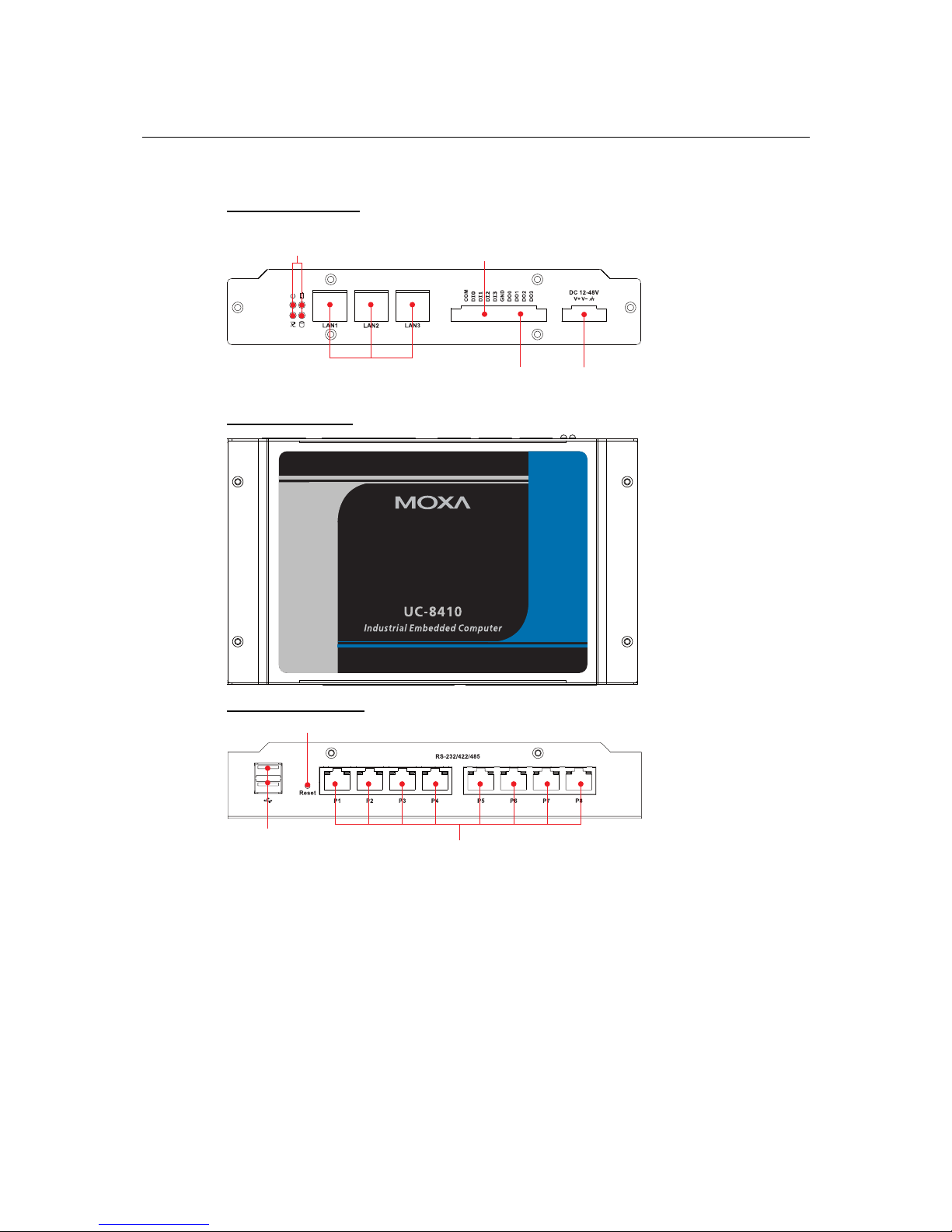
Appearance
UC-8410 Rear View
10/100 Mbps
Ethernet x 3
DI Channel x 4
DO Channel x 4 Power Input
12 to 48 VDC
LED Indicators
(Power, SRAM Battery,
Ready, Storage)
UC-8410 Top View
UC-8410 Front View
Reset Button
Serial Port x 8, RJ45
(RS-232/422/485)
USB 2.0 Host x 8
2-2
 Loading...