

Moxa Technologies UC-8112-ME-T-LX, UC-8112-ME-T-LX-US-LTE, UC-8112-ME-T-LX1, UC-8112-ME-T-US-LTE-LX1, UC-8112-ME-T Hardware User Manual
Page 1

UC-8112-ME-T Series Hardware
User’s Manual
Edition 2.1, February 2018
www.moxa.com/product
© 2018 Moxa Inc. All rights reserved.
Page 2

UC-8112-ME-T Series Hardware
Moxa Americas
Toll
Tel:
Fax:
Moxa China (Shanghai office)
Toll
Tel:
Fax:
Moxa Europe
Tel:
Fax: +49-89-3 70 03 99-99
Moxa Asia
Tel:
Fax: +886-2-8919-1231
Moxa India
Tel:
Fax:
User’s Manual
The software described in this manual is furnished under a license agreement and may be used only in accordance with
the terms of that agreement.
Copyright Notice
© 2018 Moxa Inc. All rights reserved.
Trademarks
The MOXA logo is a registered trademark of Moxa Inc.
All other trademarks or registered marks in this manual belong to their res pec tive manufacturers.
Disclaimer
Information in this document is subject to c hange witho ut no ti c e and doe s not represent a commitment on the part of
Moxa.
Moxa provides this document as is, without warranty of any kind, either expressed or implied, including, but not limited
to, its particular purpose. Moxa reserves the rig ht to make impro vem e nts and/o r changes to this manual, or to the
products and/or the programs described in this manual , at any time .
Information provided in this manual is intended to be accurate and reliable. However, Moxa assumes no responsibility for
its use, or for any infringements on the rights of third parties tha t may res ult fr om its use.
This product might include unintentional te c hnic al o r typographical errors. Changes are periodically made to the
information herein to correct such errors, and these changes are incorporated into new editions of the public atio n.
Technical Support Contact Information
www.moxa.com/support
-free: 1-888-669-2872
+1-714-528-6777
+1-714-528-6778
+49-89-3 70 03 99-0
-free: 800-820-5036
+86-21-5258-9955
+86-21-5258-5505
+886-2-8919-1230
-Pacific
+91-80-4172-9088
+91-80-4132-1045
Page 3

Table of Contents
1. Introduction ...................................................................................................................................... 1-1
Overview ........................................................................................................................................... 1-2
Model Descriptions .............................................................................................................................. 1-2
Package Checklist ............................................................................................................................... 1-2
Product Features ................................................................................................................................ 1-2
Hardware Specifications ...................................................................................................................... 1-3
Hardware Block Diagram ..................................................................................................................... 1-4
2. Hardware Introduction...................................................................................................................... 2-1
Appearance ........................................................................................................................................ 2-2
LED Indicators .................................................................................................................................... 2-3
Default Programmable Button Operations .............................................................................................. 2-3
Diagnosing Device and Subsystem Failures ..................................................................................... 2-4
Reset to Factory Default ...................................................................................................................... 2-4
Real-Time Clock ................................................................................................................................. 2-4
Placement Options .............................................................................................................................. 2-5
DIN-Rail Mounting ....................................................................................................................... 2-5
Wall Mounting (Optional) .............................................................................................................. 2-6
3. Hardware Connec tio n De scription ..................................................................................................... 3-1
Wiring Requirements ........................................................................................................................... 3-2
Connecting the Power .................................................................................................................. 3-2
Grounding the Unit ...................................................................................................................... 3-2
Connecting to the Console Port ............................................................................................................. 3-3
Connecting to the Network ................................................................................................................... 3-3
Connecting to a Serial Device ............................................................................................................... 3-4
Inserting the SD and SIM Card ............................................................................................................. 3-4
USB Port ............................................................................................................................................ 3-4
Installing the Cellular Module ............................................................................................................... 3-5
A. Regulator y Approv al S ta teme nts ....................................................................................................... A-1
Page 4

1
1. Introduction
The UC-8112-ME-T series computing platform is designe d for embed ded da ta acquisition applications. The
computer comes with two RS- 232/422/485 seri a l ports and dual 10/100 Mbps Ethernet LAN ports, as well as
a Mini PCIe socket to support cellular modules. These versatile communication capabilities let users efficiently
adapt the UC-8112-ME-T to a varie t y of c omplex communications solutio ns .
The following topics are covered in this chapter:
Overview
Model Descriptions
Package Checklist
Product Features
Hardware Specifications
Hardware Block Diagram
Page 5

UC-8112-ME-T Series Hardware Introduction
1-2
Overview
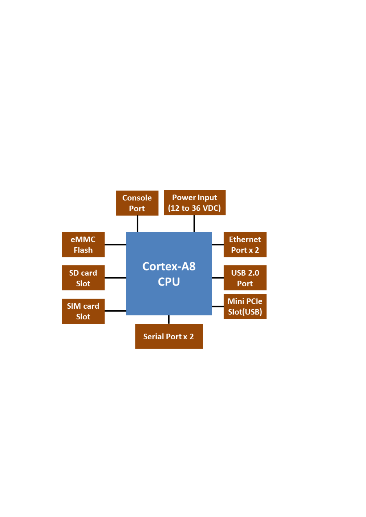
The UC-8112-ME-T is built around an ARMv7 Cortex-A8 RISC processor that has been optimized for use in
energy monitoring systems, but is widely applicable to a variety of industrial solutions. With flexible interfacing
options, this compact embedded computer is a reliable and secure gateway for data acquisition and data
processing at field sites as well as a useful communication platform for many other large-scale deployments.
Model Descriptions
The UC-8112-ME-T series includes the following models:
• UC-8112-ME-T-LX: RISC-based platform with 1 GHz CPU, 512 MB RAM, Mini PCIe socket for cellular
connectivity, 2 Ethernet ports, 2 serial ports, 4 GB eMMC flash, USB port, SD-card socket, and Debian ARM
• UC-8112-ME-T-LX1: RISC-based platform with 1 GHz CPU, 1 GB RAM, Mini PCIe socket for cellular
connectivity, 2 Ethernet ports, 2 serial ports, 4 GB eMMC flash, USB port, SD-card socket, and Debian ARM
• UC-8112-ME-T-LX-US-LTE: RISC-based platform with 1 GHz CPU, 512 MB RAM, 4 GB eMMC flash, Mini
PCIe socket for cellular connectivity (w ith c e llular module for North America built in), 2 Ethernet ports, 2
serial ports, USB port, and Debian ARM
• UC-8112-ME-T-US-LTE-LX1: RISC-based platform with 1 GHz CPU, 1 GB RAM, 4 GB eMMC flash, Mini
PCIe socket for cellular connectivity (w ith c e llular module for North America built in), 2 Ethernet ports, 2
serial ports, USB port, and Debian ARM
Package Checklist
Before installing the UC-8112-ME-T, verify tha t the packa g e contains the fo llo wing items:
• UC-8112-ME-T embedded computer
• Power ja ck
• Quick installation guide (printed)
• Warranty card
NOTE: Notify your sales representative if any of the above items are missing or damaged.
Product Features
• ARMv7 Cortex-A8 1000 MHz processor
• Dual auto-sensing 10/100 Mbps Ethernet por ts
• SD socket for storage expansion and OS installation
• Programmable LEDs and a programmable button for easy installation and maintenance
• Mini PCIe socket for cellular module
• -40°C to 70°C wide temperature range with LTE enabled
Page 6

UC-8112-ME-T Series Hardware Introduction
1-3
Computer
CPU:
USB:
DRAM:
Storage
Storage Expansio n:
• SDHC/SDXC socket for storing OS and storage
•
Ethernet Interface
LAN:
Magnetic Isolation Protection:
Serial Interface
Serial Standards:
Console Port:
Serial Communication Para me ters
Data Bits:
Stop Bits:
Parity:
Flow Control:
Baudrate:
Serial Signals
RS
RS
RS
RS
LEDs
System:
LAN:
Programmable:
Switches and Buttons
Push Button:
Physical Characteristics
Housing:
Weight:
•
•
Dimensions:
Mounting:
Environmental Limits
Operating Temperature:
Wide Temp. Models:
Wide Temp. models (with LTE accessory):
Storage Tem perature:
Ambient Relative Humidity:
Anti
500 Hz, 1 hr per axis (without any USB devices
attached)
Anti
Hardware Specifications
ARMv7 Cortex-A8 1000 MHz
USB 2.0 host x 1 (type A connector)
512 MB DDR3 S DRAM
expansion
4 GB eMMC flash with OS pre-installed
2 auto-sensing 10/ 100 Mbps ports (RJ 45)
1.5 kV built-in
2 RS-232/422/485 ports, software-selectable (5-pin terminal block connector)
RS-232 (TxD, RxD, GND), 4-pin pin header output (115200, n, 8, 1)
5, 6, 7, 8
1, 1.5, 2
None, Even, Odd, Space, Mark
XON/XOFF, ADDC® (automatic data direction co ntro l) fo r RS -485
Max. 921600 bps
-232: TxD, RxD, RTS, CTS, GND
-422: TxD+, TxD-, RxD+, RxD-, GND
-485-4w: TxD+, TxD-, RxD+, RxD-, GND
-485-2w: Data+, Data-, GND
Power x 1, USB x 1, S D x 1, and signal strength x 3
10M/100M on connector
Diagnosis x 3
Initially configured to return a diagnos tic report, and to reset the devic e to factor y def aul ts
Metal
UC-8112-ME-T-LX: 530 g (1.18 lb)
UC-8112-ME-T-LX-US: 590 g (1.31 lb)
141 x 119.9 x 36 mm (5.56 x 4.72 x 1. 4 2 in)
DIN rai l, wall mount (optional)
-40 to 85°C (-40 to 185°F)
-40 to 70°C (-40 to 158°F)
-40 to 85°C (-40 to 185°F)
5 to 95% (non-condensing)
-Vibration: 2 Grms @ IEC 60068-2-64, random wave, 5-
-Shock: 20 g @ IEC 60068-2-27, half sine wave, 30 ms
Page 7
UC-8112-ME-T Series Hardware Introduction
1-4
Power Requirements
Input Voltage:
Input Curre nt:
Power Consumption:
Standards and Cer t ifications
Safety:
EMC: EN 55032/24
Green Product:
Reliability
Alert Tools:
Automat ic Reboot Trigger:
Warranty
Warranty Period: 5 years
Details:
12 to 36 VDC (3-pin terminal block, V+, V-, SG)
500 mA @ 12 VDC
6 W (without cellular module and external USB device attached )
UL 60950-1
RoHS, C RoHS, W EEE
External RTC (real-time cloc k )
External WDT (watchdog timer)
See www.moxa.com/warranty
Hardware Block Diagram
Page 8

2
2. Hardware Introduction
The UC-8112-ME-T embedded computers are compact and rugged making them suitable for industrial
applications. The LED indicators help in monitoring performance and troubleshooting issues. The multiple ports
provided on the computer can be used to connect to a variety of devices . The UC-8112-ME-T comes with a
reliable and stable hardware platform that lets you devote the bulk of your time to application development. In
this chapter, we provide basic informa tio n abo ut the embe dde d computer’s hardware and its various
components.
The following topics are covered in this chapter:
Appearance
LED Indicators
Default Programmable Button Operations
Diagnosing Device and Subsystem Failures
Reset to Factory Default
Real-Time Clo ck
Placement Options
DIN-Rail Mounting
Wall Mounting (Optional)
Page 9
UC-8112-ME-T Series Hardware Hardware Introduc tion
2-2
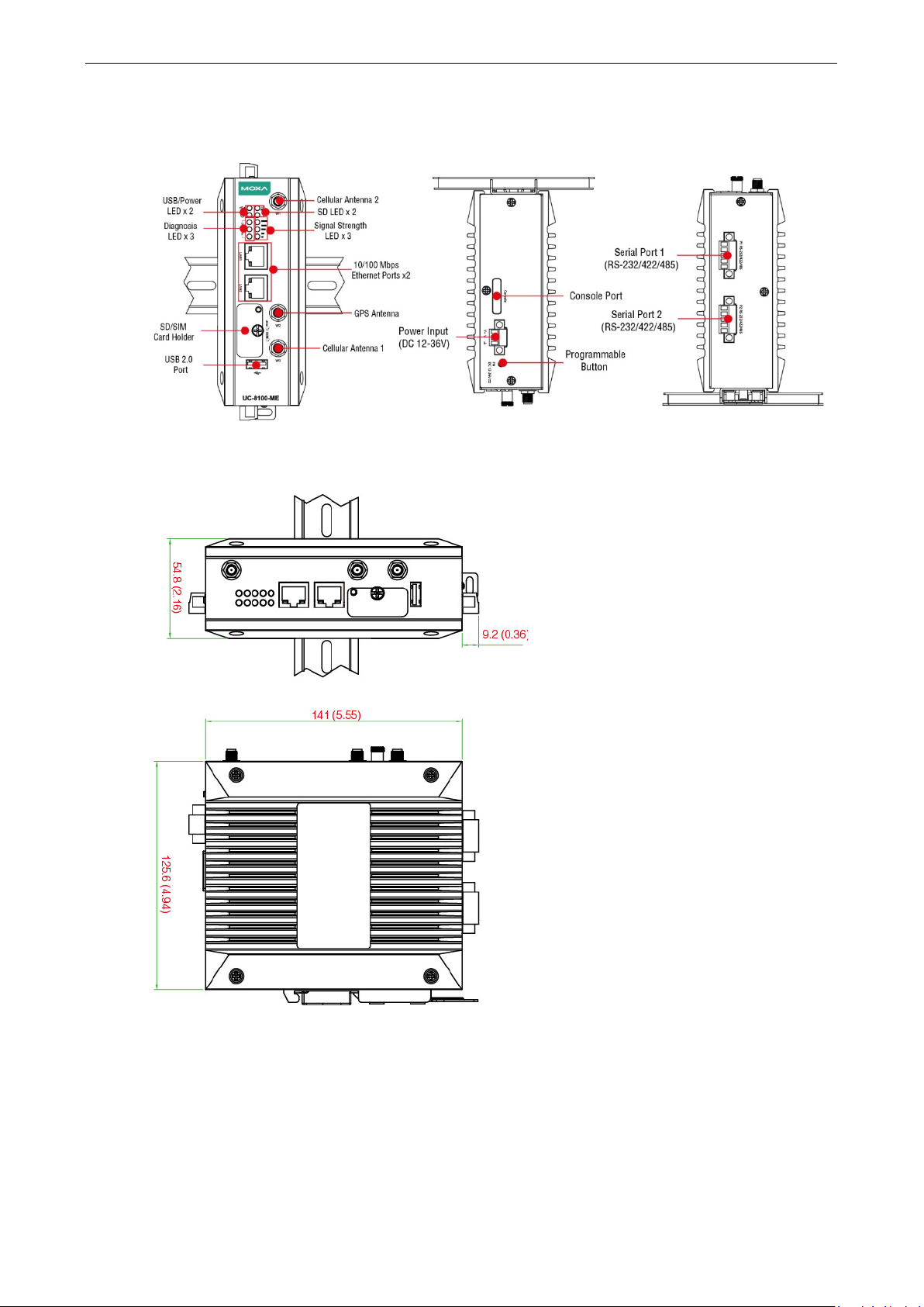
Appearance
Front View Top View Bottom View
Dimensions [units: mm (in)]
Page 10

UC-8112-ME-T Series Hardware Hardware Introduc tion
2-3
Resetting to default configuration
Blinking
Blinking
On
LED Indicators
Refer to the following table for information about each LED.
LED Name Color Function
USB Green
SD Green
Power
LAN1/2 (On RJ45
connector)
Wireless Signal
Strength
Green Power is on and the computer is working normally.
Off Power is off.
Green
Yellow
Off Ethernet is not connected.
Green
Yellow
Red
Off Wireless module is not detected.
Steady On USB device is connected and working normally.
Off USB device is not connected.
Steady On SD Card inserted and working normally.
Off SD Card is not detected.
Steady On 100 Mbps Ethernet link
Blinking Data transmission in progress.
Steady On 10 Mbps Ethernet link
Blinking Data transmission in progress.
The number of glowing LEDs indicates the signa l s trength
3 (Green + Yellow + Red): Excellent
2 (Yellow + Red) : Good
1 (Red) : Poor
Programmable
Diagnostic LEDs
Green
Yellow
Red
These 3 LEDs are programmable. Refer to the “Default
Programmable Button Operations” section for details.
Default Programmable Button Operations
The function button (FN) loc ated on the top pa ne l is used to diag nose d evic e f ailure or to perform firmware
restoration. After pressing the button, release it at the appropriate time to enter the required mode to either
troubleshoot issues in your computer or restore your computer to the default co nfig uration. Refer to the
following illustration for detaile d instructions:
Release the button during
Button pressed
RED LED
Blinking
0 2 4 7 8
The LED indicators behave differently when diagnosing a device failure compared to performing a firmware
restoration. See the following table for details:
Status Red LED Yellow LED Green LED
Executing diagnostics program Blinking Off On
this time to diagnose
device failure
GREEN LED
On
Release the button during this
time to perform restoration
RED LED
GREEN LED
Blinking
On
NO ACTION
Time (s)
Page 11

UC-8112-ME-T Series Hardware Hardware Introduc tion
2-4
ATTENTION
Reset to D
Please back up your files before resetting the system to
. All the data stored
in the
Diagnosing Device and Subsystem Failures
The red LED will start blinking once you press the function button (FN). Keep the button pressed until the green
LED is lit for the first time and then release the button to enter diagnostic mode to check which peripherals are
available on the UC-8112-ME-T-LX. When the dia g nostic program is running, the red LED will blink.
Status Red LED Y ello w LED Green LED
Diagnostics program is executing Blinking Off On
The following two tables describe the diagnostic s r e s ults related to hard w are defec ts and syste m operation.
Hardware Defects
If you observe any of these hardware issues, contact Moxa Support for f urthe r instructions.
Status Red LED Yellow LED Green LED
UART1 device issue On On Off
UART2 device issue On On Blinking
LAN 1 device issue On Off Off
LAN 2 device issue On Off Blinking
Button device issue On Blinking Off
TPM device issue On Blinking Blinking
LED device issue On Off Off
System Operation
If you observe any of the following issues, check the item indicate d by the LEDs.
Status Red LED Yellow LED Green LED
CPU usage (over 90%) Blinking On Off
RAM usage (over 90%) Off On Off
Disk usage (over 90%) Off On Blinking
File system corrupted Blinking On Blinking
Reset to Factory Default
Press and hold the function button (FN) continuously for at least 5 seconds to load the factory default
configuration. After the factory default configur ation has been loaded, the system will reboot automatically .
The Power LED will blink on and off for the first 5 seconds, and then maintain a steady glow once the system
has rebooted.
We recommend that you only use this function if the softw are is not work ing prop e rly and you want to load
factory default settings. The Reset to D efaul t functionality is not designed to hard reboot the UC-8112-ME-T.
efault will erase all the data stored o n the boot sto rag e
UC-8112-ME-T‘s boot storage will be erased when it is rese t to the factory default configuration.
the factory default configuration
Real-Time Clock
The UC-8112-ME-T’s real-time clock is powered by a lithium battery. We strongly recommend that you do not
replace the lithium battery without help fro m a qualifie d Moxa support engineer. If you need to change the
battery, contact the Moxa RMA service team.
Page 12

UC-8112-ME-T Series Hardware Hardware Introduc tion
2-5
WARNING
There is a risk of explosion if the battery is replaced
NOTE
Test the screw head and shank size by inserting the screw into one of the keyhole s haped ap er tur e s of the
wall
Placement Options
There are two sliders on the back of the unit for DIN rail and wall mounting.
DIN-Rail Mounting
1. The DIN-rail mo unting kit is mounted by default as shown in the figure below.
-mounting plates before attaching the plate to the wall.
with an incorrect battery type.
2. Pull down the bottom slide r of the DIN-r ail br ack e t loca te d at the back of the unit
3. Insert the top of the DIN rail into the s lot jus t bel ow the uppe r hook of the DIN-rail br acket.
4. Latch the unit firmly on to the DIN rail as shown in the illustrations below.
5. Push the slider back into place.
Page 13

UC-8112-ME-T Series Hardware Hardware Introduc tion
2-6
ATTENTION
The wall
Wall Mounting (Optional)
1. Remove the four screws on the side-panel silver cover of the device
2. Place the wall-mount br ack e ts on the silver cover and fasten the screws as shown below. Use only the
screws provided in the wall-mounting kit p ack age.
-mounting kit is not included in the package and must be purchased sep arate ly.
Page 14

3
3. Hardware Connection Description
This section describes how to connect the UC-8112-ME-T to a network and connect various devices to the
UC-8112-ME-T.
The following topics are covered in this chapter:
Wiring Requirements
C o nne cting the Power
Grounding the Unit
Connecting to the Console Port
Connecting to the Network
Connecting to a Serial D e vi c e
Inserting the SD and SIM Card
USB Port
Installing the Cellular Module
Page 15

UC-8112-ME-T Series Hardware Hardware Connect ion Descripti on
3-2
ATTENTION
Safety First!
Be sure to disconnect the
Electrical Current
Calculate the maximum possible curre nt in each power wir e and com mon wir e . Observe all elec trical codes
dictating the maximum current allowab le for ea c h wire siz e .
If the current goes above the maximum ratings, the wiring could overheat, causing serious damage to your
equipment.
Temperature Caution!
Be
plugged in, the internal components generate heat, and
consequently the
The
The figure show
power is properly supplied,
LED will glow a solid green
color when
system to boot up)
ATTENTION
This product is intended to be supplied by a Listed Power
at
a minimum of
Wiring Requirements
In this section, we describe how to connect various de vices to the embe dded computer. You must pay attention
to the following common safety precautions, before proceeding with the installation of any electronic device:
• Use separate paths to route wiring for power and devices. If power wir ing and devic e wir ing p aths must
cross, make sure the wires are perpendicular at the inters ectio n po int.
NOTE: Do not run the wires for signal or communication and power wiring in the same wire conduit. To
avoid interference, wires with diffe rent signal characteristics should b e route d separately.
• You can use the type of signal transmitted through a wire to determine which wires should be kept separate.
The rule of thumb is that wiring that shares similar electrical characteristics can be bundled together.
• Keep input wiring and output wiring separate.
• We strongly advise that you label wiring to all devices in the system for easy identification.
careful when handling the unit. When the unit is
power cord before installing and/or wiring the computer.
Caution!
outer casing may be hot to touch by hand.
Connecting the Power
Terminal Block
UC-8112-ME-T has a 3-pin terminal block for a 12 to 36 VDC power input.
the operating system is ready (it may take 30 to 60 seconds for the operating
s how the power input interface connects to external power sources. If the
the Power LED will light up. The Power
.
500 mA @ 12 VDCC.
Supply Unit that is rated to deliver 12 to 36 VDC
Grounding the Unit
Grounding and wire routing help limit the effects of noise due to elec tro m agnetic inte rference (EMI). Run the
ground connection from the ground screw to the grounding sur f a ce pri or to conne c ti ng dev ic e s to the
computer.
Page 16

UC-8112-ME-T Series Hardware Hardware Connect ion Descripti on
3-3
ATTENTION
This product
SG: The Shielded Ground (sometimes called Prote c ted Ground) co ntact is the
contact of the 3
wn
here. Connect the SG wire to an appropriate grounded metal surf ace.
ATTENTION
A shielded power cor
nearby
radio and television reception. I t
You are cautioned that changes or modifica tio ns no t expr essly a pprov e d by the party r espo ns ib le for
compliance could void your authority to operate the eq uipment.
The LED indicator in the lower right corner glows
reen color
when the cable is properly
network. The
being transmitted or received.
The LED indicator in
solid orange color
when the cable is properly
network. The
being transmitted or received.
is intended to be mounted to a well-grounded mounting surface, such as a metal panel.
-pin power terminal block connector when viewed from the angle sho
d is required to meet FCC emission limits and also to prevent interference with
is essential that only the supplied power cord be used.
Connecting to the Console Port
bottom
The UC-8112-ME-T is provided with a 4-pin pin-heade r RS-232 console port, which is a located on the top panel.
This port is designed for connecting serial console terminals, which you can use to view the boot up messages,
and to troubleshoot when the system does not boot up.
Serial Console Port & Pinouts Serial Console Cable
Pin Signal
1 TxD
2 RxD
3 NC
4 GND
Connecting to the Network
Connect one end of the Ethernet cable to one of the UC-8112-ME-T’s 10/100M Ethernet ports (8-pin RJ 45) and
the other end of the cable to the Ethernet network. If the cable is properly connected, the UC-8112-ME-T will
indicate a valid connection to the Etherne t in the following ways:
a solid g
connected to a 100 Mbps Ethernet
LED will flash on and off when Ethernet packets are
the upper right corner glows a
LED will flash on and off when Ethernet packets are
connected to a 10 Mbps Ethernet
Pin Signal
1 ETx+
2 ETx3 ERx+
4 –
5 –
6 ERx7 –
8 –
Page 17

UC-8112-ME-T Series Hardware Hardware Connect ion Descripti on
3-4
RS
ATTENTION
The
disconnect the
Connecting to a Serial Device
Use certified s erial cables to connect the UC-8112-ME-T to serial devices. The serial ports of the UC-8112-ME-T
use the 5-pin terminal block. The ports can be configured by software for RS-232, RS-422, or 2-wire RS-485.
The pin assignments are shown in the following table:
Terminal Block
-232/422/485 Pinouts
Pin RS-232 RS-422 RS-485
1 TXD TXD+ –
2 RXD TXD- –
3 RTS RXD+ D+
4 CTS RXD- D5 GND GND GND
Inserting the SD and SIM Card
The UC-8112-ME-T comes with an SD-card socket for storage expansion, and a SIM-card socket that can be
used to install a SIM card for cellular communication. The SD card/SIM card sockets are located on the lower
part of the front panel. To install the cards, remove the screw and the protection cove r to access the sockets,
and then plug the SD card and the SIM card into the sockets directly. Remember to push in on the SD card or
SIM card first if you want to remove them.
The SD card will be mounted at: /mnt/sd
USB Port
UC-8112-ME-T does not support SD-card hot swap or PnP (Plug and Play) functionality. You must
The UC-8112-ME-T is provided with 1 USB 2.0 full speed port (OHCI), type A connector, which supports a
keyboard or mouse, as well as an external flash disk for storing d ata.
power source to the computer before you insert or remov e the SD card.
Page 18

UC-8112-ME-T Series Hardware Hardware Connect ion Descripti on
3-5
Installing the Cellular Module
The UC-8112-ME-T is provided with a PCIe socket for installing a cellular module. To install the cellular module,
do the following:
1. Remove the four screws on the DIN-rail mounting
kit.
3. Remove the four screws on the silver cover on the
right panel and take off the cover.
2. Remove the two screws on the rear panel.
4. Remove the screw on metal cover.
5. Remove the three screws on the top panel. 6. Remove the two screws on the bottom panel.
Page 19
UC-8112-ME-T Series Hardware Hardware Connect ion Descripti on
3-6
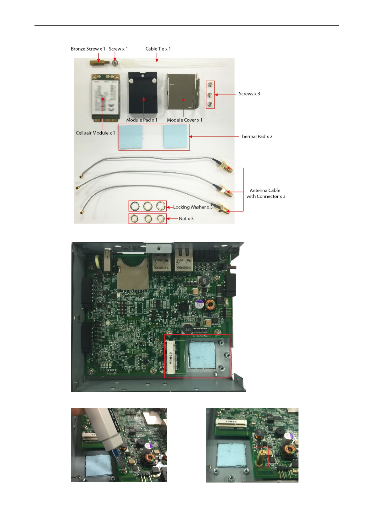
7. Check the contents of the cellular module package. The package should contain the items shown below:
8. Remove the metal cover of the computer and lo c ate the cellular module socket.
9. Remove the screw next to the socket and replace it with the bronze screw (in the package) as shown below:
Page 20

UC-8112-ME-T Series Hardware Hardware Connect ion Descripti on
3-7
10. Attach one thermal pad to the ce llula r module cover and the other thermal pad to the module pad.
11. Attach the cellular module to the module pad.
12. Mount the module cover on the ce llula r module a nd use screws on bo th side s to sec ure the cov er .
Page 21
UC-8112-ME-T Series Hardware Hardware Connect ion Descripti on
3-8
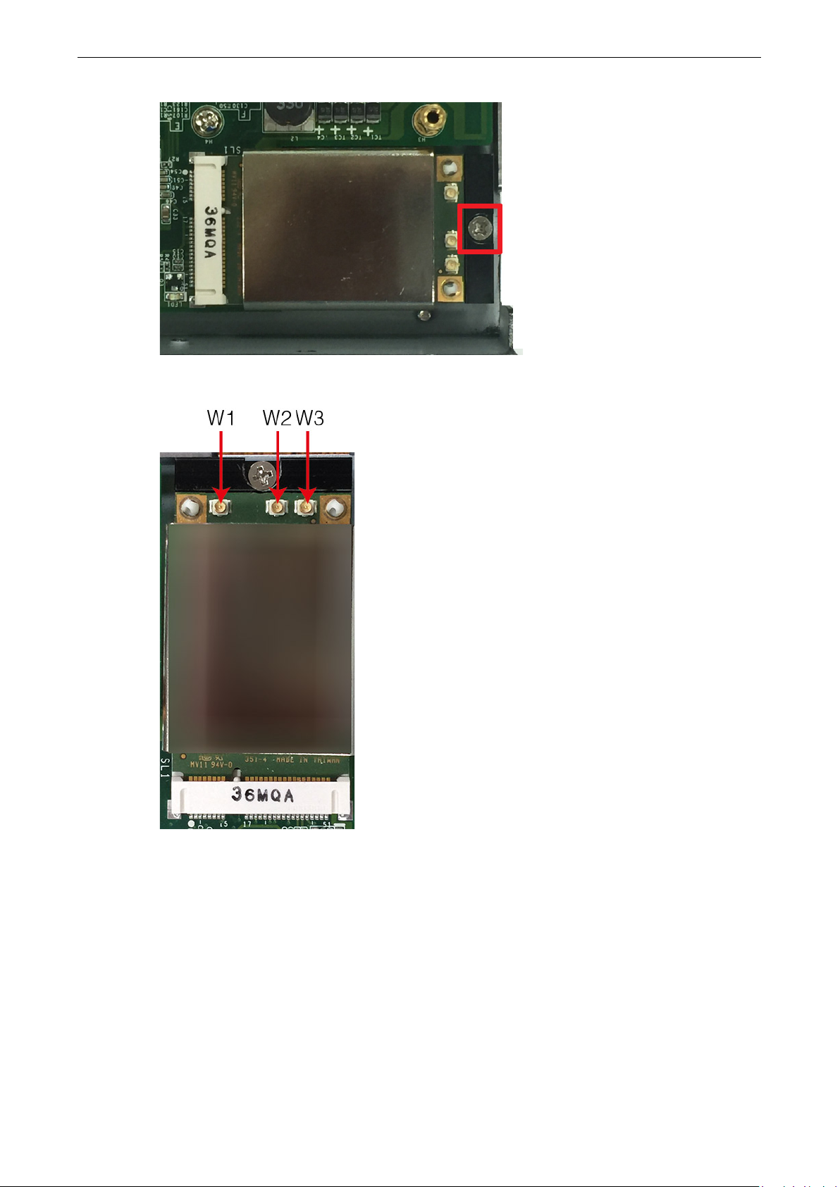
13. Insert the module into the socket and s ecur e it using a scr ew fro m the pa cka ge.
14. Connect antenna cables to the cellular module. There are three antenna connectors on the cellular module:
W1 and W3 are for cellular antennas and W2 is for GPS antenna.
Page 22
UC-8112-ME-T Series Hardware Hardware Connect ion Descripti on
3-9
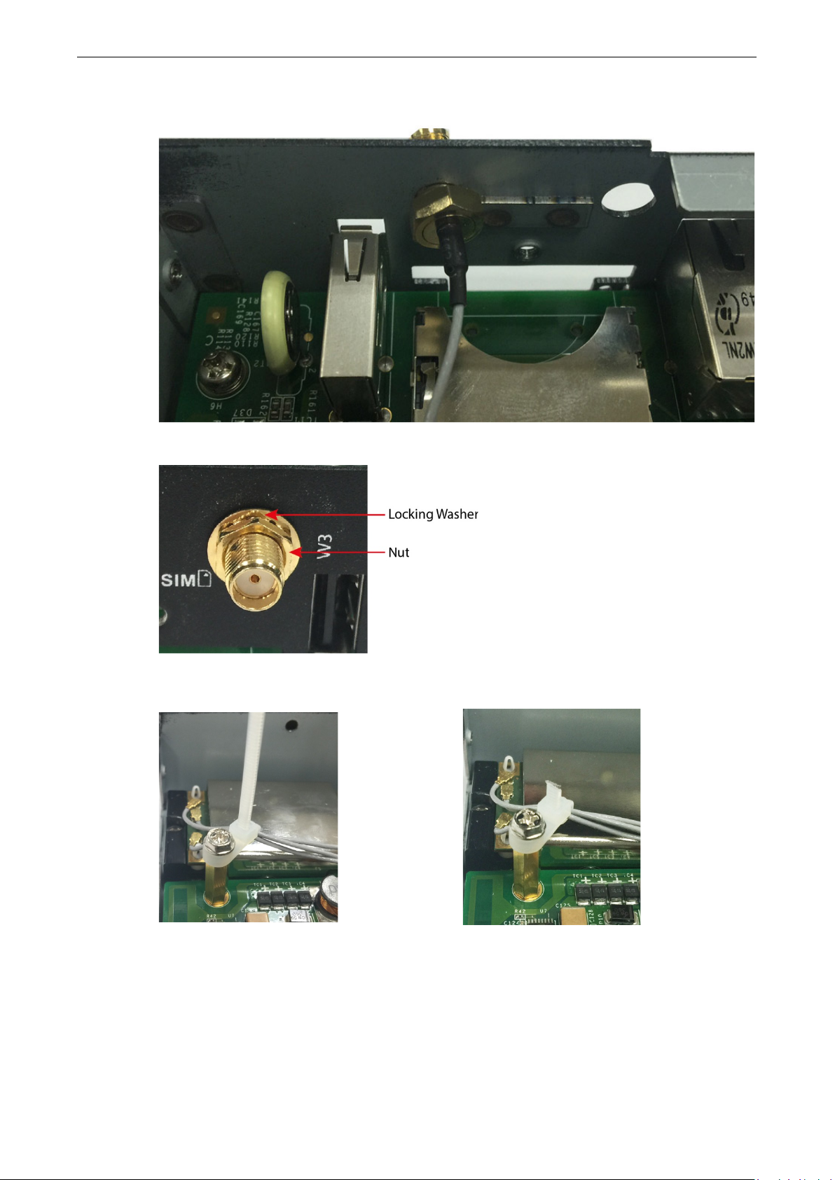
15. Insert the antenna co nne c tor s thr o ugh the antenna cable holes on the front panel of the cover as shown
below:
16. Secure the antenna co nne c tors to the cove r using a locking washer and nut as shown below:
17. Arrange the antenna cables and use a cable tie to attach the cables to the bronze screw. You may cut the
cable tie if it is too long.
Page 23
UC-8112-ME-T Series Hardware Hardware Connect ion Descripti on
3-10
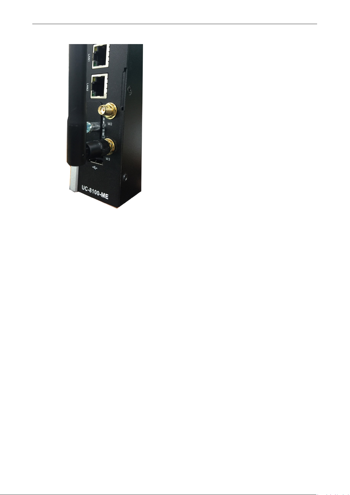
18. Plug the antenna onto the connecto r.
19. Replace the cover of the computer and fasten the screws to secure the cover.
Page 24
This device complies with part 15 of the FCC Rules . Operation is subject to the following
two conditions: (1) This device may not cause har mful inte rf e re nc e , and (2 ) this dev ic e
must accept any interference received , including interference that may cause undesired
operation.
European Community
WARNING
This is a class A product. In a domestic environment this product may cause radio interference in which case
the user may be required to take adequate measures.
A
A. Regulatory Approval Statements
Class A: FCC Warning! This equipment has been tested and found to comply with the limits for a Class A digital
device, pursuant to part 15 of the FCC Rules. These limits are des igned to provi d e re aso nable prote c tion
against harmful interference when the equip m e nt is operated in a commerc ia l e nvir o nment. This eq uipment
generates, uses, and can radiate radio frequency energy and, if not installed and used in accordance with the
instruction manual, may cause harmful interf ere nc e to radio communi c ations. Operation of this equipment in
a residential area is likely to cause harmful interference in which case the users will be required to correct the
interference at their own expense.
 Loading...