

Page 1
— 1 — — 2 — — 3 —
UC-7420/7410-CE
Quick Installation Guide
Second Edition, June 2008
1. Overview
MOXA UC-7420/7410 features eight RS-232/422/485 serial ports, dual
10/100 Mbps Ethernet ports, PCMCIA, and a CompactFlash interface
for wireless LAN communication and flash disk expansion, making
UC-7420/7410 ideal for your embedded applications.
2. Package Checklist
Before installing UC-7420/7410, verify that the package contains the
following items:
y 1 UC-7410 or UC-7420
y Wall-Mounting Kit
y DIN-Rail Mounting Kit
y UC-7420/7410 Quick Installation Guide (this guide)
y UC-7420/7410 Documentation & Software CD
y Cross-over Ethernet cable
y CBL-RJ45M9-150: 150 cm, 8-pin RJ45 to Male DB9 serial port cable
y CBL-RJ45F9-150: 150 cm, 8-pin RJ45 to Female DB9 console port
cable
y Universal Power Adaptor
y Product Warranty Statement
Please notify your sales representative if any of the above items are
missing or damaged.
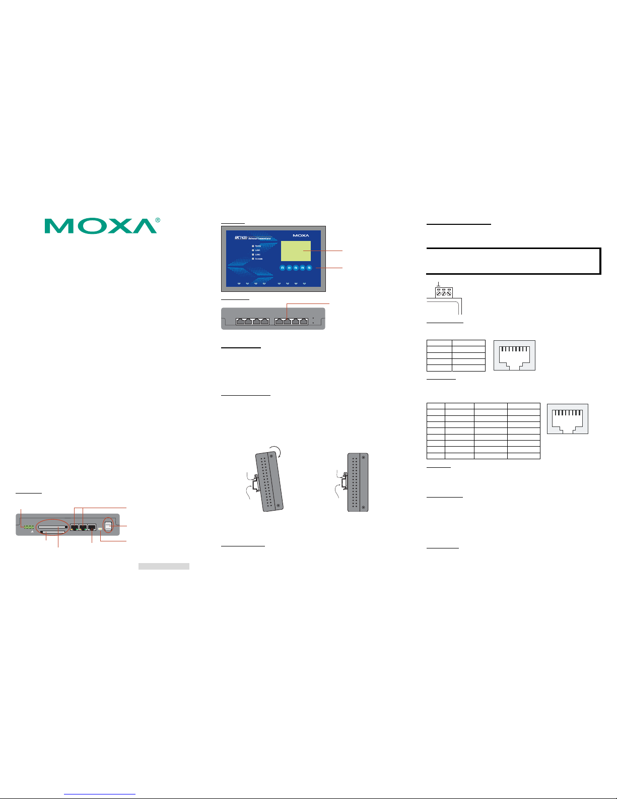
3. UC-7420/7410 Panel Layout
NOTE: UC-7420 (shown in the figures) has a CF slot, PCMCIA slot,
and two USB 2.0 Host ports (circled below). UC-7410 does NOT have
these three features.
Rear View
DC 12-48V
USB
LAN1 LAN2 Console
V+ V-
PCMCIA
CF
12-48 VDC
Power Input
CF x 1
PCMCIA x 1
10/100 Mbps Ethernet x 2
USB 2.0 Host x 2,
A Type Connector
USB 1.1 Client x 1,
miniB Connector
RS-232
PPP/Console
Top View
Graphics LCM
160 x 64 Dots
5 Buttons
Front View
Reset
P1
RS-232/422/485
P2 P3 P4 P5 P6 P7 P8
Reset to
default
RJ45 RS-232/422/485
Connectors x 8
4. Installing UC-7420/7410
Wall or Cabinet
The two metal brackets included with UC-7420/7410 can be used to
attach it to a wall, or the inside of a cabinet. Using two screws per
bracket, first attach the brackets to the bottom of the UC-7420/7410.
Next, use two screws per bracket to attach the UC-7420/7410 to a wall
or cabinet.
DIN-Rail Mounting
The aluminum DIN-Rail attachment plate is included in the package.
To attach the plate to UC-7420/7410, situate the stiff metal spring
towards the top.
STEP 1: Insert the top of the
DIN-rail into the slot just below the
stiff metal spring.
STEP 2: The DIN-Rail attachment
unit will snap into place as shown
below.
metal
spring
DIN-Rail
metal
spring
DIN-Rail
To remove UC-7420/7410 from the DIN-Rail, simply reverse Steps 1
and 2 above.
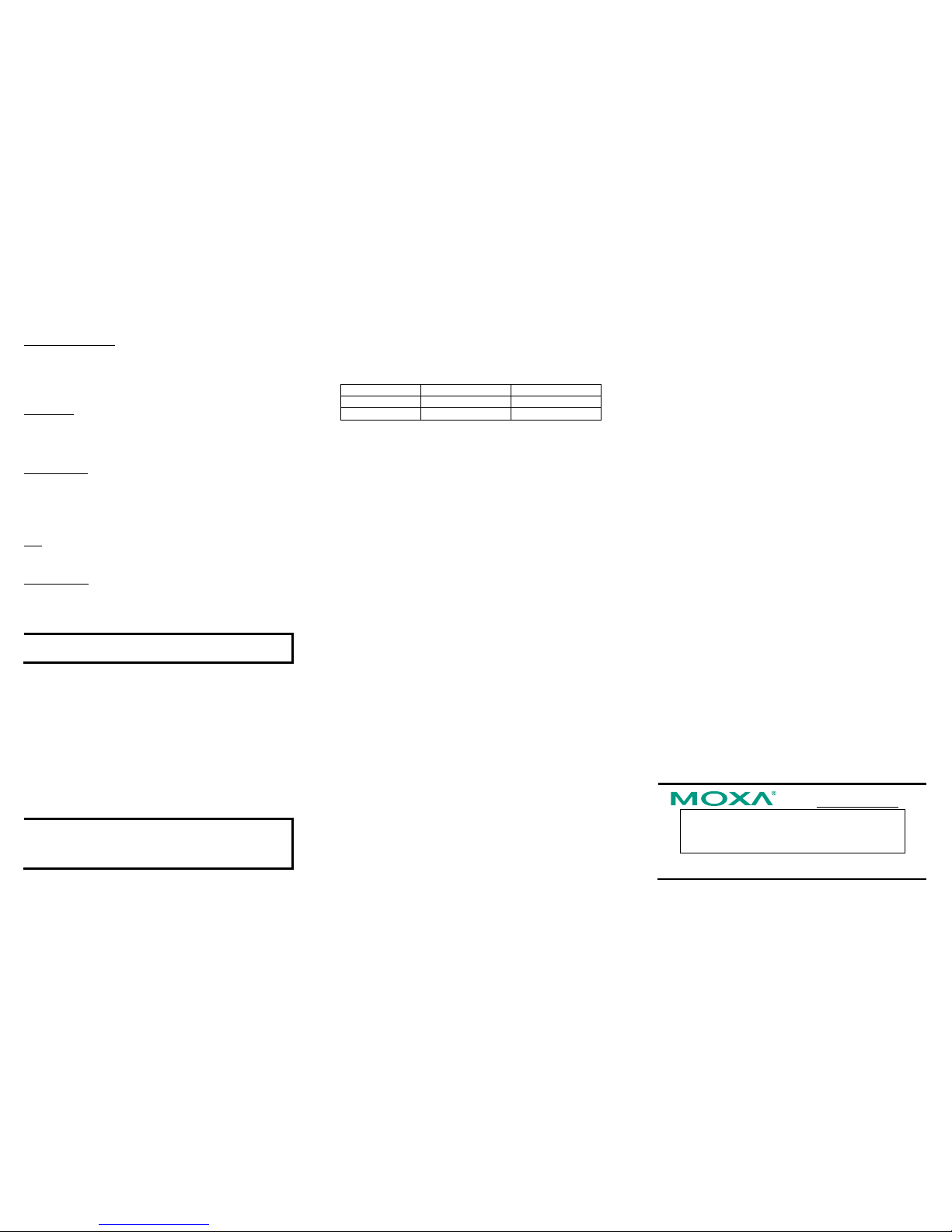
5. Connector Description
Power Connector
Connect the 12-48 VDC power line to UC-7420/7410’s terminal block.
If the power is properly supplied, the Ready LED will will show a solid
green color when the OS is ready.
Grounding UC-7420/7410
Grounding and wire routing help limit the effects of noise due to
electromagnetic interference (EMI). Run the ground connection from the
ground screw to the grounding surface prior to connecting the power.
ATTENTION
This product is intended to be mounted to a well-grounded mounting
surface such as a metal panel.
SG
SG:
The Shielded Ground (sometimes called Protected
Ground) contact is the left most contact of the
3-pin power terminal block connector when
viewed from the angle shown here. Connect the
SG wire to an appropriate grounded metal surface.
Ethernet Ports
The 10/100 Mbps Ethernet ports (LAN 1 and LAN 2) use RJ45
connectors.
Pin Signal
1 ETx+
2 ETx3 ERx+
6 ERx-
81
Serial Ports
The eight serial ports (P1 to P8) use RJ45 connectors. Each port can be
configured by software for RS-232, RS-422, or RS-485. The pin
assignments are shown in the following table:
Pin RS-232 RS-422 RS-485
1 DSR --- --2 RTS TXD+ --3 GND GND GND
4 TXD TXD- --5 RXD RXD+ Data+
6 DCD RXD- Data7 CTS --- --8 DTR --- ---
81
PCMCIA
The PCMCIA slot supports the CardBus (Card-32) Card standard and
16-bit (PCMCIA 2.1/JEIDA 4.2) Card standard. It supports +3.3V, +5V,
and +12V at a working voltage of 120 mA.
CompactFlash
UC-7420 provides one CompactFlash slot that supports CompactFlash
type I/II card expansion. Currently, MOXA provides a CompactFlash
disk for plug & play expansion. You may also use flash disks available
from most computer supply outlets. The CompactFlash will be
mounted at
\> CFFolder
Console Port
The console port is an RJ45 RS-232 port. It is designed for serial
console, and can be connected to a V90 or GPRS modem via PPP. The
pin definitions are the same as for the eight serial ports (P1 to P8).
P/N: 1802074001011
Page 2
— 4 — — 5 — — 6 —
Reset to Default Button
Press the “Reset to Default” button continuously for at least 5 seconds
to load the factory default configuration. After the factory default
configuration has been loaded, the system will reboot automatically.
The Ready LED will blink on and off for the first 5 seconds, and then
maintain a steady glow once the system has rebooted.
Reset Button
Press the “Reset” button to activate the hardware reset function. You
should only use this function if the software does not function properly.
To reset a system, you should reboot the operating system to avoid
deleting important data.
LCM & Keypad
UC-7420/7410 Series has an LCM screen and five input buttons on the
top panel. Refer to the Moxa Device API for programming information.
The LCM can display 16 columns and 8 rows of text with ASCII code
starting from 0x20 to 0x7F. The function of the five keypad buttons can
be defined by your application.
USB
The USB 2.0 Host port now supports a USB storage device driver. The
USB 1.1 Client port is reserved for future enhancement.
Real Time Clock
UC-7420/7410’s real time clock is powered by a lithium battery. We
strongly recommend that you do not replace the lithium battery without
help from a qualified MOXA support engineer. If you need to change
the battery, contact the Moxa RMA service team.
ATTENTION
There is a risk of explosion if the battery is replaced by an incorrect type.
6. Powering on UC-7420/7410
To power on UC-7420/7410, connect the “terminal block to power jack
converter” to the UC-7420/7410's DC terminal block (located on the
left back panel), and then connect the power adaptor. Note that the
Shielded Ground wire should be connected to the right most pin of the
terminal block. It takes about 30 seconds for the system to boot up.
Once the system is ready, the Ready LED will light up, and
UC-7420/7410’s network settings will appear on the LCM display.
7. Connecting UC-7420/7410 to a PC
There are two ways to connect UC-7420/7410 to a PC, through the
serial console port or by Telnet over the network. The COM settings for
the serial console port are: Baudrate = 115200 bps, Parity = None,
Data bits = 8, Stop bits = 1, Flow Control = None.
ATTENTION
Remember to choose the “VT100” terminal type. Use the
CBL-RJ45F9-150 cable included with the product to connect a PC to
UC-7420/7410’s serial console.
To use Telnet you will need to know UC-7420/7410’s IP address and
netmask. The default LAN settings are shown below. For first-time
configuration, you may find it convenient to use a cross-over Ethernet
cable to connect the PC directly to the UC-7420/7410.
Default IP Address Netmask
LAN 1 192.168.3.127 255.255.255.0
LAN 2 192.168.4.127 255.255.255.0
Once the UC-7420/7410 is powered on, the Ready LED will light up,
and a login page will open. Use the following default Login name and
Password to proceed.
Login: admin
Password: admin
8. Configuring the Network Setting
Normally, you are required to change the IP address of UC-7400-CE
because it is located in a different local network from that of your
development workstation. Use the netconfig utility to complete the task.
Before using this utility, type netconfig -h to examine the usage of the
command.
\> netconfig –h
Usage: netconfig –n <“LAN1” or “LAN2”> [-m <netmask>] [-d
<DNS server>] [-g <gateway>] [-i <IP address>]
For example, your development workstation has a LAN port at
192.168.1.x and the Domain Name Server (DNS) is at 192.168.2.6.
Execute the following command.
\> netconfig –n LAN1 –i 192.168.1.5 –m 255.255.255.0 –g
192.168.1.254 –d 192.168.2.6
Type netconfig to view the new settings.
\> netconfig
LAN1 Interface Configuration:
IP Address: 192.168.1.5
SubNet Mask: 255.255.255.0
Gateway: 192.168.1.254
DNS: 192.168.2.6
LAN2 Interface Configuration:
IP Address: 192.168.4.127
SubNet Mask: 255.255.255.0
Gateway:
DNS:
9. Developing Your Application
Application development on the UC-7400-CE computer takes
advantage of a number of well-known tools that are provided by the
Windows environment in programmers’ workstations. These tools are
trouble-free to use for Windows programmers. Check the following
development tools for Windows Embedded Application Development.
y VB.NET/C# Applications: Use Visual Studio 2005
y VB.NET/C# Applications: Use Visual Studio .NET 2003
y C/C++ Applications: Use eMbedded Visual C++ (eVC) 4.0
Visual Studio 2005
You do not need to install additional packages.
Visual Studio .NET 2003
1. Install Visual Studio .NET 2003
2. Install Windows® CE Utilities for Visual Studio .NET 2003 Add-on
Pack (550KB) for VB .NET
3. Import Compact .NET Framework SDK
eMbedded Visual C++ (eVC) 4.0
1. Install eMbedded Visual C++ 4.0 (230 MB)
2. Install Service Pack 4 for eVC 4.0 (68 MB)
3. Install MOXA Windows® CE 5.0 C/C++ SDKs
Developing applications with eVC 4.0 and MOXA SDKs
1. Open Microsoft® eMbedded Visual C++ 4.0.
2. From the File menu, choose New.
3. Choose the Projects tab and then select the type of application.
4. In the Project name box, type project name, then click OK.
5. Choose the application type you want to create and click Finish.
6. On the Build toolbar, choose the MOXA UC-7400-CE SDK, the
type of run-time image (Release or Debug), and the UC-7400-CE
device.
7. Write your application code.
8. From the Build menu, choose Rebuild All to build the application.
9. When you complete your application, use the web-based
management system to upload it to the target computer.
Developing a VB.NET / C# application with .NET Compact
Framework
1. Open Microsoft® Visual Studio .NET 2003.
2. From the File menu, choose New Æ Project.
3. Choose the Project Type and then select the Smart Device
Application type of application.
4. In the Project name box, type a name for the project, and then click
OK.
5. Choose the Windows CE target platform.
6. Select the project type and click OK.
7. Write your application code.
8. From the Device toolbar, choose Windows CE.NET Device.
9. From the Build menu, choose Build Project or Rebuild Project.
10. When you complete your application, use the web-based
management system to upload it to the target computer.
Click here for online support:
www.moxa.com/support
The Americas: +1-714-528-6777 (toll-free: 1-888-669-2872)
Europe: +49-89-3 70 03 99-0
Asia-Pacific: +886-2-8 919-1230
China: +86-21-5258-9955 (toll-free: 800-820-5036)
© 2008 Moxa Inc., all rights reserved.
Reproduction without permission is prohibited.
 Loading...