

Page 1
Serial Port Powered Media Conversion Solution
Transio TCC-82 User’s Manual P/N: 1802000820011 Third Edition.
www.moxa.com ©2008 Moxa Inc.
Moxa Inc.
All rights reserved.
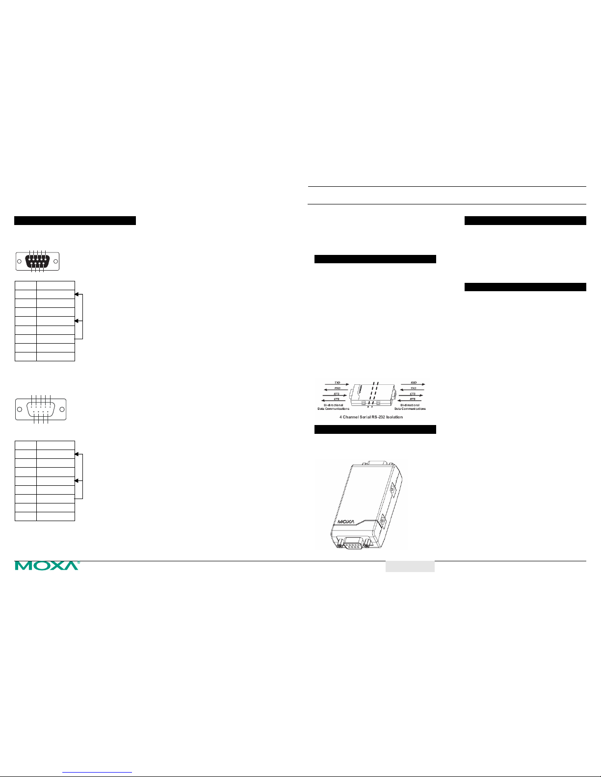
RS-232 Pinouts
The female DB9 port and RS-232 pinouts for the
port are shown below.
5 4 3 21
9
68 7
PIN RS-232
1 DCD
2 TxD
3 RxD
4 DSR
5 GND
6 DTR
7 CTS
8 RTS
The male DB9 port and RS-232 pinouts for the port
are shown below.
12345
6789
PIN RS-232
1 DCD
2 RxD
3 TxD
4 DTR
5 GND
6 DSR
7 RTS
8 CTS
Note: The DTR, DSR and DCD pins are shorted
as shown above so that users do not need
to worry about signal control cable wiring.
Transio TCC-82 V2.0
4-channel, self-powered RS-232 signal isolator
(4KV RMS for 1 min. isolation) with 15 KV ESD
protection
Overview
The TCC-82 is a signal isolator that provides
bi-directional serial communication with full
electrical isolation between two RS-232 devices.
This compact isolator isolates both sides of the
connection, providing perfect protection from
ground loops, lightning surge coupling, and
accidental high voltage shorts. The internal
magnetic coupler is tested to ensure that it can
withstand more than 4 KV rms input-to-output for 1
minute. This guarantees that the TCC-82 not only
meets the requirements of general serial data
communications, but also the high standards
required by industrial automation and medical
applications. In addition to the TxD and RxD data
lines, the TCC-82 also protects the RTS/CTS
handshake lines on its two D-type connectors.
Package Checklist
• TCC-82 RS-232 Signal Isolator
• 2 USB Power Cords
• User’s Manual
Applications
• Medical facilities
• Terminal connections
• Factory automation
• Remote serial device control
• Building security automation
• Critical industrial control
• Surveillance systems
Features and Specifications
• Serial interface: RS-232
• Serial port type: DB9 (1 male, 1 female)
• Compact size
• Auto senses baud rates up to 115.2 Kbps
• Signals:
RS-232 Isolation: TxD, RxD, RTS and CTS;
• RS-232 loop back: DTR to DSR and DCD
• 15 KV ESD protection for all RS-232 signals
• Serial Power Source: TxD, RTS, or DTR
• External Power (jack connector): DC +5V to
+12V adaptors or by USB power cords.
• Operating temperature: 0 to 60°C (32 to 140°F)
• Dimensions: 42 x 80 x 23.6 mm
• Casing: ABS + PC
• Weight: 60 ± 5g
• CE, FCC Class B approval
• Power Consumption: 10 mA at +5 VDC
• Warranty : 5 years
shorted
shorted
Page 2
Transio TCC-82 User’s Manual Transio TCC-82 User’s Manual
Installation
Independent Serial Port Power
TCC-82 has two power inputs, which means that
both sides of the isolator must be powered
independently and separately to maintain the
isolation. Ideally, both sides can get power directly
from the RS-232 TxD data lines and the RTS/DTR
handshake lines, regardless of whether the signal is
high or low. This also eliminates the need to use
external power supplies for most systems. The
configuration of the wires and the entire system can
be maintained easily.
In most situations, the TCC-82 can get enough
power from the attached Tx line. If the attached
serial device does not provide enough power
through the Tx line, additional handshake lines can
used to power the TCC-82.
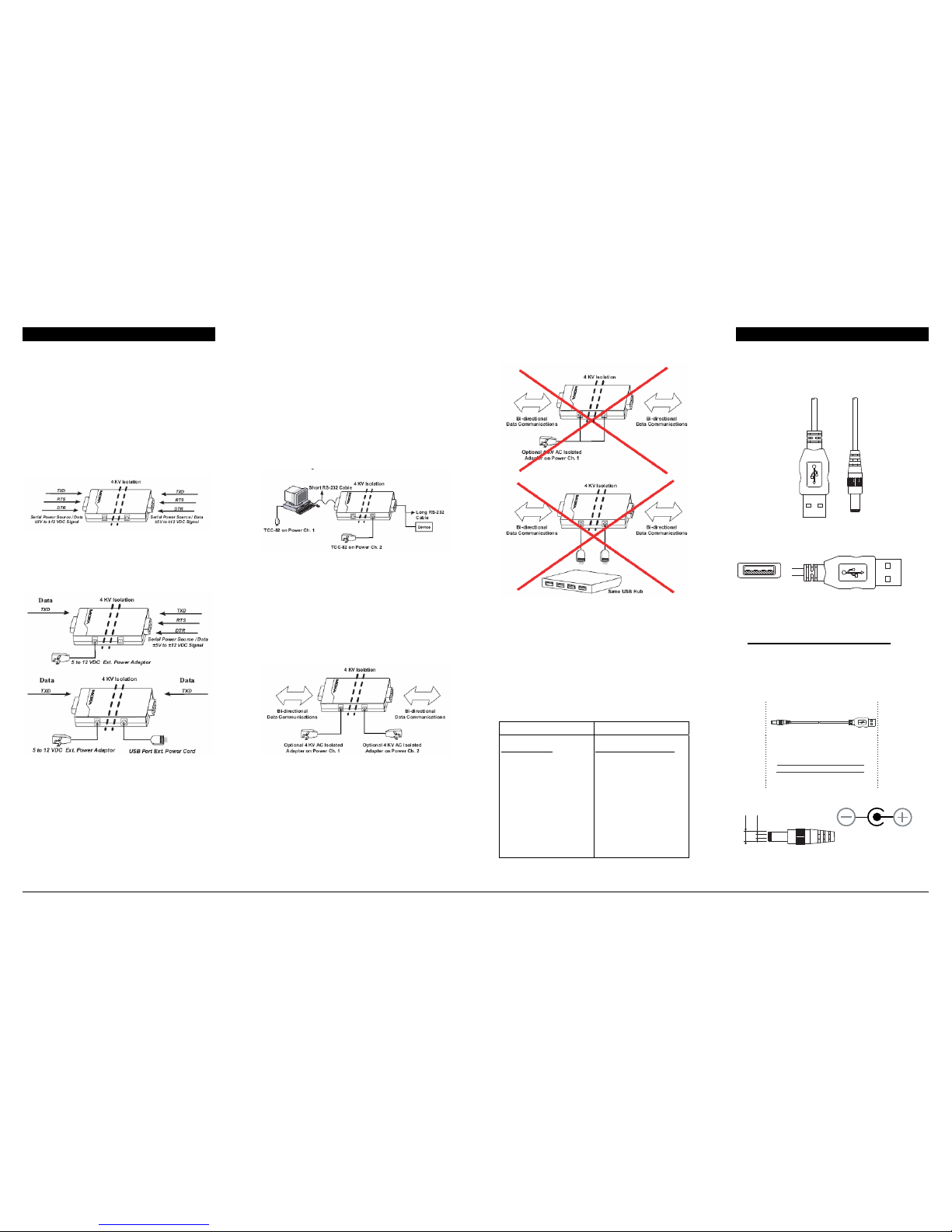
Implementing External Power
When connecting the TCC-82, all output signals
should be connected, since the TCC-82 derives
power from these signals, even if they are not used
by your system to transmit data signals. Care should
be taken when implementing the external power
supply. Usually, one side of the TCC-82 is attached
to the host PC by a short serial cable. On the other
side, the serial cable may be too long and the power
from the remote device will not be sufficient to
activate the other end of the TCC-82. Refer to the
following figure to see an example that implements
external power.
It is also important to use the external power supply
if the TCC-82’s full 4 KV of isolation is required to
operate correctly. Most of the commercial power
supplies that are available on the market only
provide 1500 VAC or less of isolation between the
primary and secondary windings. If both sides of
the isolator require external power, then two
separate isolated 4 KV protected power supplies are
required.
NOTE: Be sure to connect the two power adaptors
to different power channels.
Using different power inputs for the two power
channels is an integral part of the isolation design.
DO NOT implement your power system as follows:
Compatibility of Serial Interfaces
Different kinds of serial ports use different interface
chips, and provide different power levels. In fact,
some ports will not provide enough power to
activate the TCC-82.
You will seldom encounter problems with a PC’s
onboard COM1 and COM2 ports. Refer to the
following table for add-on cards and
serial-to-Ethernet device server that are guaranteed
to provide sufficient power.
Multiport Serial BoardsSerial Device Servers
Moxa Boards
CP-168U Series
CP-104U Series
CP-102U Series
C168H Series
C104H Series
Moxa NPort Servers
CN2510
CN2610
NPort5110
NPort5210
NPort5410
NPort5610
NPort6150
NPort6250
NPort6450
NPort6650
Optional USB Power Cord
If additional external power is required, the TCC-82
can be connected to a standard 5 to 12 VDC power
supply, or a USB power cord.
CBL-USBAP-50
USB “A” Male Connector
Front:
4 3 2 1
To p:
TCC-82 USB Connector
Connector Pinouts Signals
1 +5 VDC
2 -3 -4 GND
28-CCT
renni
retuo
gulP rewoP C
D
05-PAB
SU-L
BC
BSU
tsoH BSU
elameF epyT A
CDV 5+
D
NG
gniriW elbaC
1
4
12 VDC
10 mA (max.)
Ø2.1±0.1
Ø5.1±0.1
 Loading...