

Page 1

P/N: 1802065120010
*1802065120010*
TN-G6512 Series
Quick Installation Guide
Moxa ToughNet S witch
Edition 1.0, December 2018
Technical Support Contact Information
www.moxa.com/support
Moxa Americas:
Toll
-free: 1-888-669-2872
Tel:
1-714-528-6777
Fax:
1-714-528-6778
Moxa China (Shanghai office):
Toll
-free: 800-820-5036
Tel:
+86-21-5258-9955
Fax:
+86-21-5258-5505
Moxa Europe:
Tel:
+49-89-3 70 03 99-0
Fax:
+49-89-3 70 03 99-99
Moxa Asia-Pacific:
Tel:
+886-2-8919-1230
Fax:
+886-2-8919-1231
Moxa India:
Tel:
+91-80-4172-9088
Fax:
+91-80-4132-1045
2018 Moxa Inc. All rights reserved.
Page 2

- 2 -
Overview
The ToughNet TN-G6512 series of M12 manag ed Eth ern et s witches are
designed for railway applications, including r olling stock and wayside
installations. The switches use M12 and other circular connectors to
ensure tight, robust connections, and guarantee reliable operatio n in
industrial environments where vibration and shock are commonplace.
The TN-G6512 series of Ethernet switches provide 12 gigabit Ethernet
M12 ports; 8 ports support IEEE 802.3at/af compliant PoE functionality.
These PoE switches are cl assified as power source equipm ent (PSE); they
provide up to 30 watts of power per port, and can be used to power IEEE
802.3at/af co mp l iant powered devices (PDs), such as IP came r as,
wireless access points, and IP phones.
The TN-G6512 Series has push-pull M12 connectors that are tailor-made
for push-pull cables in order to facilitate quick installation, and also allow
M12 rotary cables to be utilized. The 24 to 110 VDC wide power input
range and isolated dual power inputs not only allow the same type of
power source at diff eren t sites around the globe, but also increase the
reliability of communications systems. Furthermore, the -40 to 70°C
operating temperature capability and IP67-rated enclosure make the
switches suitable for deployment in harsh environments. The TN-G6512
series of Ethernet switches are compliant with the essential sections of EN
50155, covering operating temperature, power input voltage, surge, ESD,
and vibration, as well as conformal coating and power insulation, which
makes the switches suitable for a variety of industrial applications.
Package Checklist
Your ToughNet TN-G6512 switch is shipped with the following items. If
any of these items are missing or damaged, please contact your customer
service representative for assistance.
• TN-G6512 switch
• M12-to-DB9 console p o rt cable
• 15 protective caps for the power connec t or, all Ethernet ports,
consol e port, and USB storage port (already fixed on switch)
• Pa nel mo untin g kit
• Quick insta l lation g uide ( p rinted)
• Warranty card
Features
Anti-Vibration Push-Pull/Circular Connectors for Robust Links
• M12 X-coded 8-pin female connectors for gigabit Ethernet
10/100/1000BaseT(X) ports
• M12 B-coded 5-pin female connector for serial console port
• M12 A-coded 5-pin female connector for USB storage port
• M12 K-coded 5-pin male connector for power input
Isolated Power Inputs
• Supports 24 to 110 VDC (16.8 to 137.5 VDC)
High Performance Network Switching Technology
• Provides up to 30 watts per PoE port with a total power budget of 96
watts per switch
• IPv6 Ready logo awarded (IPv6 Logo Commi t te e c er tified)
• DHCP Option 82 for IP address assignment with different policies
Page 3

- 3 -
• Turbo Ring and Turbo Chain (recovery time < 50 ms @ 250 switches),
and STP/RSTP/MSTP for network redundancy
• IGMP snooping and GMRP for filtering multicast traffic
• EtherNet/IP and Modbus/TCP industrial Ethernet protocols supported
• Port-based VLAN, IEEE 802.1Q VLAN, and GVRP to ease network
planning
• QoS (IEEE 802.1p/1Q and ToS/DiffServ) allows real-time traffic
classification and prioritization
• IEEE 802.3ad, LACP for optimum bandwidth utilization
• SNMPv1/v2c/v3 for different l evels of network management
• TACACS+, SNMPv3, IEEE 802.1X, HTTPS, and SSH to enhance
network security
• RMON for efficient network monitoring and proactive capability
• Bandwidth management prevents unpredictable network status
• Lock port allows access by only authorized MAC addresses
• Port mirroring for on line debugging
• Automatic warning by exception through email and relay output
• Line-swap fast recovery
• LLDP for automatic topology discovery in network management
software
• Configurable by web browser, Telnet/serial console, CLI, and
Windows utility
• Loop protection prevents network loops
Designed for Industry-Specific Applications
• Twelve Gigabit Ethernet ports to meet high bandwidth requirements.
• Complies with all EN 50155 mandatory test items*
• -40 to 70°C operating temperature range
• IP67-rated rugged case
• Pa nel mo untin g inst allation ca p abi l ity
*This product is suitable for rolling stock railway applications, as defined
by the EN 50155 standard. For a more detailed statement, click here:
www.moxa.com/doc/specs/EN_50155_Compliance.pdf
Recommende d Optional Accessories
• CBL-M12XMM8PRJ45-Y-200-IP67: 2-meter M12-to-RJ45 Cat-5 UTP
Ethernet cable with IP67-rated 8-pin male X-coded crimp type M12
connector
• CBL-M12XMM8P-Y-300-IP67: 3-meter M12-to-M12 Cat-5 UTP
Ethernet cable with IP67-rated 8-pin male X-coded crimp type M12
connector
• CBL-M12XMM8P-Y-100-IP67: 1-meter M12-to-M12 Cat-5 UTP
Ethernet cable with IP67-rated 8-pin male X-coded crimp type M12
connector
• M12X-8PMM-IP67-HTG: Field-installable M12 X-coded crimp type,
slim design connector, 8-pin male, IP67-rated
• A-CAP-M12F-M-PP: Metal Cap for M12 female push-pull connector
Page 4
- 4 -
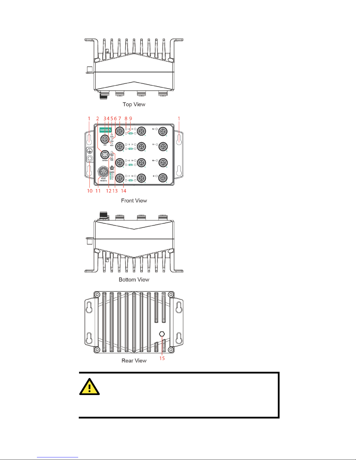
Panel Layout s
1. Scre w holes f o r panel
mounting kit
2. Console port
3. USB port
4. FAULT LED
5. PWR1 LED:
for power input 1
6. PWR2 LED:
for power input 2
7.
10/100/1000BaseT(X) port
(M12 X-coded 8-
pin female
connector)
8.
10/100/1000BaseT(X) port
LED
9. PoE LED
10.
Grounding screw
11.
Power input port (M12
K-coded 5-pin male
connector)
12.
CPLR/TAIL LED: for ring
coupler or chain tail
13.
MSTR/HEAD LED: for ring
master or chain head
14.
Alignment mark for
X-coded connector
15.
Waterproo f ve n t
ATTENTION
Exposed connectors when not in use must be tightly covered wi th
protective caps (an optional accessory) to ensure IP
67-rated
protection.
Page 5
- 5 -
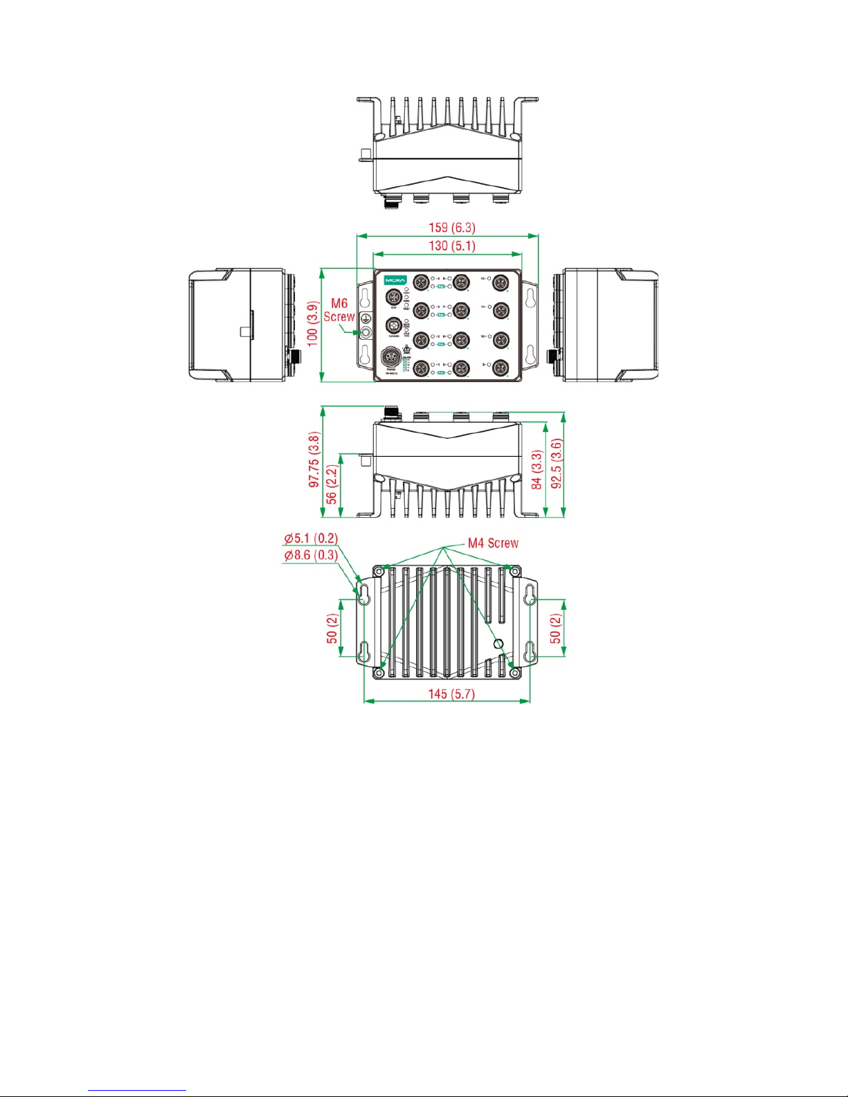
Mounting Dime nsions (unit = mm)
Page 6

- 6 -
Panel/Wa ll Mounting
STEP 1: Mounting the TN-G6512 to a wall requires 4 screws. Use the
ToughNet switch as a guide to mark the correct positions of the 4 screws.
STEP 2: Use the 4 screws in the
panel mounting kit. If you would like
to use your own screws, make sure
the screw head
is
between 6.0 mm
and 7.0 mm
in diameter and the
shaft
is less than 4.0 mm in
diameter, as shown
at the right.
Do not screw the screws in all the way—leave a space of about 2 mm to
allow room for sliding the ToughNet switch between the wall and the
screws.
NOTE
Before tighteni n g the screws into the wall, make sure the screw
head and shaft size are suitable by inserting the screw through
one of the keyhole-shaped apertures of the ToughNet switch.
STEP 3: Once the screws are fixed in the wall, hang the ToughNet switch
on the 4 screws through the large opening of the keyhole-shaped
apertures, and then slide the switch downwards. Tighten the four screws
for added stability.
NOTE
To provide greater protection from vibration and shock, use
screws with shaft diameter b etween 6.0 mm and 7.0 mm, and fix
the ToughNet switch onto the wall directly through the large
opening of the keyhole-shaped apertures.
Wiring Requ irements
WARNING
Turn the power off before disconnecting modules or wires. The
correct power supply voltage is listed on the product label. Check
the voltage of your power source to make sure you are using the
correct voltage. Do NOT use a voltage great
er than what is
specified on the product label.
These devices must be supplied by a SELV source as defined in
the Low Voltage Directive 2006/95/EC and 2004/108/EC.
Page 7

- 7 -
ATTENTION
Safety First!
Be sure to disconnec t the power
cord before instal ling an d/ or
wiring your Moxa s witch .
This device has UL 61010-2-201
approval. Use copper conductors only,
70
°C, and tighten to 4.5
pound-inches. For use in pollution degree 2 environme nt s .
ATTENTION
Safety First!
Observe all electrical codes dictating the
maximu m cu r r e n t
allowable for each wire size. If the current
goes above the
maximum ratings, the wiring could overheat,
causing seriou s
damage to your equipment.
Please read and follow these guidelines:
• Use separate paths to route wiring for power and devices. If power
wiring and device wiring paths must cross, make sure the wires are
perpendicular a t the in t ersection point.
NOTE: Do not run signal or communications wiring and power wiring
through the same wire conduit. To avoid interference, wires with
different signal characteristics should be routed separately.
• You can use the type of signal transmitted through a wire to
determine which wires should be kept separate. The rule of thumb is
that wiring that shares similar electrical characteristics can be
bundled together.
• Keep input wiring and output wiring separated.
• It is strongly advised that you label wiring for all devices in the system
when necessary.
Grounding the ToughNet Swit c h
Grounding and wire routing help limit the effects of noise due to
electromagnetic interference (EMI). Run the ground connection from the
grounding screw to the grounding surface prior to connecting devices.
Page 8

- 8 -
ATTENTION
This product
is intended to be mounted to a well-grounded
mounting surface such as a metal panel.
Connecting t h e Power Supplie s
ToughNet TN-G6512 series switches support dual power inputs—power
input 1 and power input 2. The M12 K-coded 6-pin male connector on the
TN-G6512 series switches' front panel is used for the dual power inputs.
Pinouts for the power input port
PIN
PWR
1
V1+
2
V1–
3
V2–
4
V2+
PE
GND
Pin
Description
Usage
1 PWR1 / DC +
Connect “PWR1 Live / DC +” to the positive (+)
terminal when using a DC power source.
2 PWR1 / DC –
Connect “PWR1 Neutral / DC –” to the negative (–)
terminal when using a DC power source.
3 PWR2 / DC –
Connect “PWR2 Neutral / DC –” to the negative (–
)
terminal when using a DC power source.
4 PWR2 / DC +
Connect “PWR2 Live / DC +” to the positive (+)
terminal when using a DC power source.
PE Ch a ssis G rou n d
Connect the “Chassis Ground” to the equipment
ground bus for DC inputs.
STEP 1: Plug your power cord connector into the power input port of the
TN-G6512 switch.
STEP 2: Screw the nut on your p ower cord connector into the power input
connector on the switch to ensure a tight connection.
ATTENTION
Before connecting the
TN-G6512
series to the power input, make
sure the power source voltage is stable.
ATTENTION
Do not power on
the TN-G6512 series before connec ting the M1
2
power connector.
Page 9

- 9 -
Connecting t h e D a ta Lines
10/100/1000BaseT(X) Ethernet Port Connection
The TN-G6512 Series has 12 10/100/1000BaseT(X) Ethernet ports (M12
X-coded 8-pin female connector). The 10/100/1000TX ports located on
the front panel of the TN-G6512 Series are used to connect to
Ethernet-enabled devices. Most users configure these ports for Auto
MDI/MDI-X mode, in which case the port’s pinouts are adjusted
automatically depending on the type of Ethernet cable used
(straight-through or cross-over), and the type of device (NIC-type or
HUB/Switch-type) connected to the port.
In what follows, we giv e pinouts for both MDI (NIC-type) ports and MDI-X
(HUB/Switch-type) ports. We also give cable wiring diagrams for
straight-through and cross-over Ethernet cabl es .
Pinouts for t he 10/100/1000BaseT(X) M12 (8-pin) Port
M12 (8-pin, M) to M12 (8-pin, M) Cross-Over Cable Wiring
Page 10

- 10 -
M12 (8-pin, M) to M12 (8-pin, M) Straight-Trough Cable Wiring
M12 (8-pin, M) to RJ45 (8-pin) Cross-Over Cable Wiring
M12 (8-pin, M) to RJ45 (8-pin) Straight-Trough Cable Wiring
Page 11

- 11 -
ATTENTION
The protectiv e cove r must be
fixed properly to e nsure IP67
protection. Use a torque wrench set to a torque of
12.5 kgf-m
when
tightening the screws. Note that applying a larger torque may
damage the protecti ve cover.
LED Indicato rs
Several LED indicators are located on the ToughNet switch’s front panel.
The function of each LED is described in the table below.
LED
Color
State
Description
System LEDs
PWR1 AMBER
ON
Power is being supplied to power input
PWR1.
OFF
Power is not being supplied to power
input PWR1
PWR2 AMBER
ON
Power is being supplied to power input
PWR2.
OFF
Power is not being supplied to power
input PWR2.
FAULT RED
ON
When the corresponding PORT alarm
is enabled, and a user-configured
event is triggered .
OFF
When the corresponding PORT alarm
is enabled and a user-configured
event is not triggered , or when the
corresponding PORT alarm is disabled.
MSTR/
HEAD
GREEN
ON
When the TN switch is either the
Master of this Turbo Ring, or the Head
of this Turbo Chain.
Blinking
When the TN switch is Ring Master of
this Turbo Ring and the Turbo Ring is
broke n, or it is the
Chain Head of this
Turbo Chain and the Turbo Chain is
broken.
OFF
When the TN switch is neither the
Master of this Turbo Ring, nor the
Head of this Turbo Chain.
CPLR/
TAIL
GREEN
ON
When the TN switch enables the
coupling function to form a back-up
path in this Turb o Ring, o r it is the Tail
of this Turbo Chain.
Blinking
When Turbo Chain is down.
OFF
When the TN switch disables the
coupling function of
Turbo Ring, or it is
not the Tail of the Turbo Chain.
FAULT +
MSTR/HEAD +
CPLR/TAIL
Rotate Blinking
Sequentially
When ABC-02 is importing or
exporting files.
Page 12

- 12 -
LED
Color
State
Description
Port LEDs
TP Ports
(10/100/
1000M,
for copper
ports)
AMBER
On
TP port’s 10 or 100 Mbps link is active.
Blinking
Data is being transmitted at 10 or 100
Mbps.
OFF
TP port’s 10 or 100 Mbps link is
inactive.
GREEN
ON
TP port’s 1000 Mbps link is active.
Blinking
Data is being transmitted at 1000
Mbps.
OFF
TP port’s 1000 Mbps link is inactive.
PoE Ports AMBER
ON
Power is being supplied to a Powered
Device (PD)
OFF
Power is not being supplied to a
Powered Device (PD)
Specifications
Technology
Standards
IEEE 802.3 for 10BaseT
IEEE 802.3u for 100BaseT(X)
IEEE 802.3ab for 1000BaseT(X)
IEEE 802.3x for Flow Control
IEEE 802.1D for Spanning Tree Protocol
IEEE 802.1w for Rapid STP
IEEE 802.1Q for VLAN Tagging
IEEE 802.1s for Multiple Spanning Tree Protocol
IEEE 802.1p for Class of Service
IEEE 802.1X for Authentication
IEEE 802.3ad for Port Trunk with LACP
Software Features
Management
IPv4/IPv6, SNMP v1/v2c/v3, Telnet, LLDP, Port
Mirror, Syslog, RMON, BootP, DHCP Server/Client,
DHCP Option 66/67/82, TFTP, SMTP, RARP, HTTP,
HTTPS, SNMP inform, Flow Control, Back pressure
flow control
Filter
802.1Q VLAN, Port-Based VLAN, GVRP, IGMPv1/v2,
GMRP, Static Multicast
Redundancy
Protocols
STP/RSTP, MSTP, Turbo Ring v1/v2, Turbo Ring v2
with DRC, Turbo Chain, Link Aggregation
Security
RADIUS, TACACS+, SSL, SSH, Port Lock, Broadcast
Storm Protection, Rate Limit
Time Management
SNTP, NTP Server/Client
MIB
MIB-II, Ethernet-like MIB, P-BRIDGE MIB,
Q-BRIDGE MIB, Bridge MIB, RSTP MIB, RMON MIB
Group 1, 2, 3, 9
Switch Properties
Priority Queues
4
Max. Number o f
Available VLANs
256
VLAN ID Range
VID 1 to 4094
IGMP Groups
256
Page 13

- 13 -
Interface
Gigabit Ethernet
Front cabling, M12 X-coded 8-pin connector,
10/100/1000BaseT(X) auto negotiation speed, F/H
duplex mode, auto MDI/MDI-X connection
Console Port
M12 B-coded 5-pin female connector
USB Storage Port
M12 A-coded 5-pin female connector
System LED
Indicators
PWR1, PWR2, FAULT, MSTR/HEAD, CPLR/TAIL
Port LED Indicators
10/100/1000M (Gigabit Ethernet port), PoE
Power Requirements
Input Voltage
24/36/48/72/96/110 VDC
Operating Voltage
16.8 to 137.5 VDC
Input Current
Max. 5.8 A @ 24 VDC
Connection
M12 K-coded 5-pin male connector
Overload Current
Protection
Present
Reverse Polarit y
Protection
Present
Physical Characteristics
Housing
Metal
IP Rating
IP67 protection (protective caps available for unused
ports)
Dimensions
(W × H × D)
159 x 97 x 100 mm (6.26 x 3.82 x 3.94 in)
Weight
1,750 g (3.86 lb)
Installation
Panel mounting
Environmental Limits
Operating
Temperature
-40 to 70°C (-40 to 158°F)
Storage
Temperature
-40 to 85°C (-40 to 185°F)
Operating Humidity
5 to 95% (non-condensing)
Regulatory Approvals
Safety
UL 61010-2-201, EN 60950-1 (LVD)
EMC
EN 55032, EN 55024
EMI
CISPR 32, FCC Part 15B Class A
EMS
IEC 61000-4-2 ESD: Contact: 6 kV; Air: 8 kV
IEC 61000-4-3 RS: 80 MHz to 6 GHz: 20 V/m
IEC 61000-4-4 EFT: Power: 2 kV; Signal: 2 kV
IEC 61000-4-5 Surge: Power: 2 kV; Signal: 2 kV
IEC 61000-4-6 CS: 10 V
IEC 61000-4-8
Rail Traffic
(for panel mounting installations)
EN 50155*, EN 50121-4, EN 50121-3-2, EN 45545-2
*This product is suitable for rolling stock railway applications, as defined
by the EN 50155 standard. For a more detailed statement, click here:
www.moxa.com/doc/specs/EN_50155_Compliance.pdf
Shock
EN 50155, IEC 61373
Freefall
IEC60068-2-31
Vibration
EN 50155, IEC 61373
Please check Moxa ’s web sit e for the mos t up-to-date certificatio n status.
MTBF (mean time between failures)
Time
471,356 hrs
Standard
Telcordia SR332
Page 14

- 14 -
Regulatory Approvals
Warranty Period
5 years
Details
See www.moxa.com/warranty
 Loading...