

Moxa Technologies TN-5516, TN-5518 Hardware Installation Manual

2010 Moxa Inc. All rights reserved.
Reproduction without permission is prohibited.
P/N: 1802055160013
TN-5516/5518 Series
Hardware Installation Guide
Moxa ToughNet Switch
Fourth Edition, November 2010

f
.
.
s
nsole and relay output.
.
/VAC (88 to 300 VDC, 85 to 264 VAC),
s.
y
e Protocol) for the precise time
nt with different policies.
• Turbo Ring, Turbo Chain,and RSTP/STP (IEEE802.1w/D).
Overview
The ToughNet TN-5516/5518 series M12 managed Ethernet switches are
designed for industrial appl ications in hars h environments . The TN series
switches use M12 connectors to ensure tight, robust connections, and
guarantee reliable operation against environmental disturbances , such as
vibration and shock. The wide selection of 12/24/36/48 VDC, 72/96/110
VDC, or 110/220 VDC/VAC dual redundant power supplies increases the
reliability of your communications. The TN-5516 switches provide up to
16 fast Ethernet M12 ports.
The TN-5518 switches provide up to 16 fast Ethernet M12 ports, and the
2 ports located on the bottom provide a Gigabit Ethernet interface with
bypass relay option. Models with an extended operating temperature
range of -40 to 75°C are also available. The TN-5516/5518 series
Ethernet switches are compliant with EN50155/50121-3-2/50121-4
(railway applications), NEMA TS2 (traffic control systems), and e-Mark
(vehicles) requirements, making the swit ches suitable for a variety o
industrial applications.
Package Checklist
Your ToughNet TN-5516/5518 switch is shipped with the following items.
If any of these items is missing or damaged, please contact your
customer service representative for assistanc e.
• 1 Moxa ToughNet switch.
• Hardware ins tallation gu id e.
• CD-ROM with user’s manual, Windows utility, and SNMP MIB file
• Moxa product warranty statement
• M12 to DB9 console port cable.
r console and relay output port• 2 protective caps fo
• Panel mounting kit.
Features
Anti-Vibration Circular Connectors for Robust Links
• M12 D-coding 4-pin female connectors for Fast Ethernet
10/100BaseT(X) ports.
• M12 connectors for Gigabit Ethernet 10/100/1000BaseT(X) ports
• M12 A-coding 5-pin male connectors for co
• M23 6-pin male connector for power input
Dual, Isolated Redundant Power Inputs
• Supports 12/24/36/48 VDC (8.4 to 60 VDC).
• Supports 72/110 VDC (50.4 to 54 VDC), isolated.
• Supports 110/220 VDC
isolated.
• Dual redundant, parallel load-sharing power supplie
High Performance Network Switching Technolog
• IPv6 ready, certified by the IPv6 Logo Committee.
• IEEE 1588 PTP (Precision Tim
synchronization of networks.
• DHCP Option 82 for IP address assignme
• Modbus/TCP industrial Ethernet protocol.
- 2 -

• IGMP Snoop ing and GMR P for filter ing multic ast traff ic from indus tria
Ethernet protocols.
l
.
.
.
.
.
t
.
r
P
stallable M12 D-coded screw-in connector,
llable M12 A-coded screw-in connector,
DK-DC50131: DIN-Rail mounting kit, 50 x 131 mm.
• P
ort-based VLAN, IEEE802.1Q VLAN, and GVRP protocol to ease
network planning.
• QoS (IEEE802.1p/1Q and TOS/DiffServ) to increase determinism
• 802.3ad, LACP for optimum bandwidth utilization.
• IEEE802.1X and https/SSL to enhance network security.
• SNMP v1/v2c/v3 for different levels of network management.
• RMON for efficient network monitoring and proactive capability
• Bandwidth management prevents unpredictable network status
• Lock port allows access by only authorized MA C addresses
• Port mirroring for online debugging.
• Automatic warning by exception through email, relay output
• Automatic recovery of connected devices’ IP addresses.
• Line-swap fast recovery.
• LLDP for automatic topology discovery through net work managemen
software.
• Configurable through Web browser, Telnet/Serial console, and
Windows utility.
Designed for Industry-specific Applications
• Two Gigabit Ethernet ports to meet high bandwidth requirements.
• Bypass relay option on the 2 Gigabit Ethernet ports ensure non- sto p
data communication in the event the switch stops working due to a
power failure .
• Three rotary switches for setting the last 3 digits of the IP address
makes maintenance even easier.
a• EN 50155/50121-3-2/50121-4, NEMA TS2, and e-Mark compli
• e (for “-T” models).
nt
-40 to 75°C operating temperature rang
• IP54/IP67, rugged high-strength case.
• Panel mounting or DIN-Rail mounting installation capability.
Recommended Optional Accessories
• CBL-M23(FF6P)Open-BK-100-IP67: 1-meter M23 to 6-pin powe
cable with IP67-rated female 6-pin M23 connector.
• CBL-M12D(MM4P)/RJ45-100 IP67: 1-meter M12-to-RJ45 Cat-5E UT
Ethernet cable with IP67-rated male 4-pin M12 D-coded connector.
• CBL-M12(FF5P)/OPEN-100 IP67: 1-meter M12-to-5-pin power cable
with IP67-rated female 5-pin M12 A-coded connector.
• M12D-4P-IP68: Field-in
male 4-pin, IP68-rated.
• M12A-5P-IP68: Field-insta
female 5-pin, IP68-rated.
• CAP-M12F-M: Metal cap for M12 female connector
•
- 3 -

TN-5516 Panel Layouts
15
17
16
17
Botton View
Rear View
1
2
2
3
4
5
6
7
8 9 10 11 12
13
14
18
19
.
hielded M23 connector).
for power input 2.
ad.
ler or chain tail.
aseT(X) port (female 4-pin shielded M12 connector with D
ver with Model name1. 3 Rotary switches and protective co
r panel mounting kit. 2. Screw holes fo
3. Console port.
4. Grounding screw.
5. Relay output port.
6. Power input voltage range indication.
7. Power input port (male 5-pin s
8. PWR1 LED: for power input 1.
9. PWR2 LED:
10. FAULT LED.
11. MSTR/HEAD LED: for ring master or chain he
12. CPLR/TAIL LED: for ring coup
13. TP port’s 10/100 Mbps LED.
14. 10/100B
coding).
15. Waterproof vent.
.
E1 LED: Not used by the TN-5516 series.
16. Product labe l.
17. 12 Screw holes for DIN-Rail mounting kit.
18. E2: LED: Not used by the TN-5516 series
19.
- 4 -
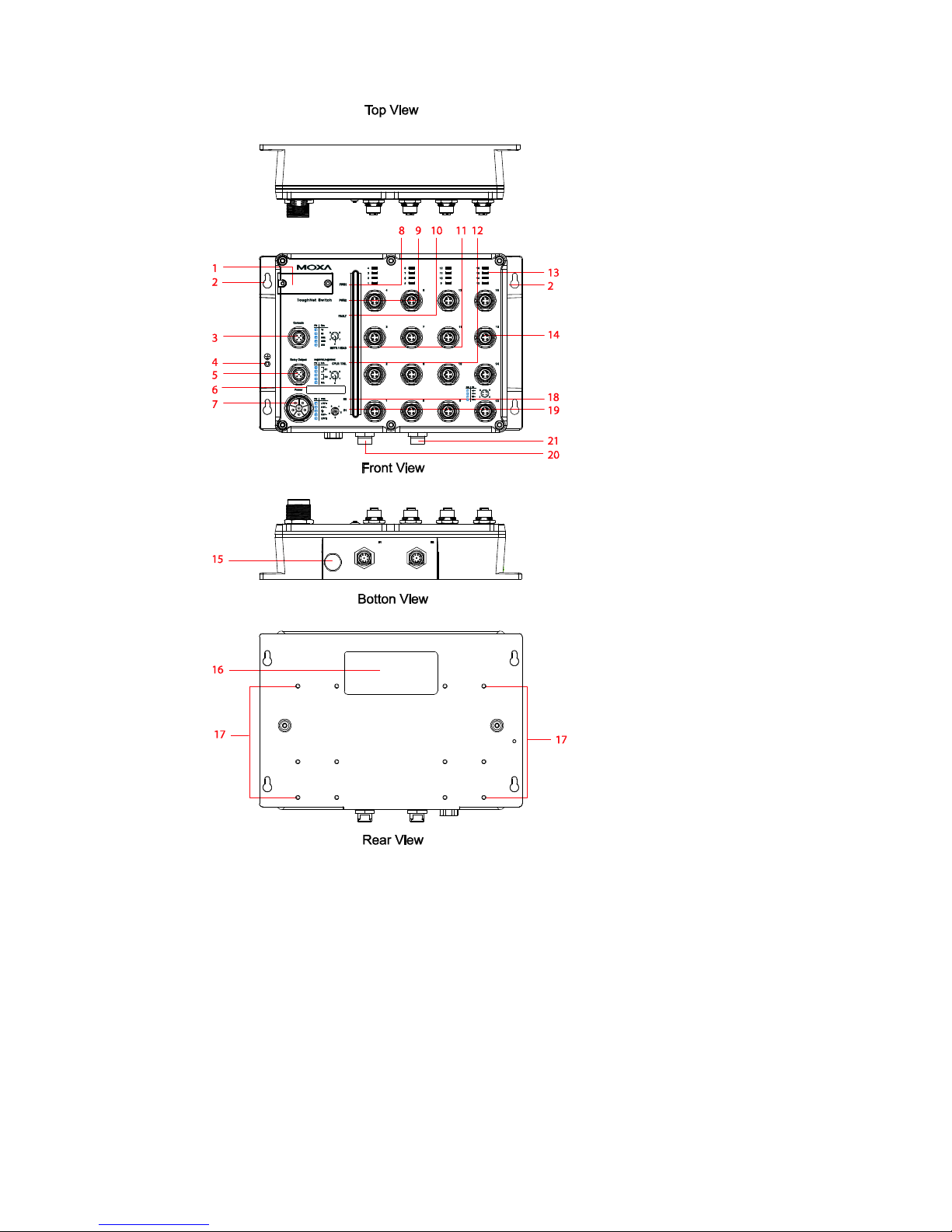
TN-5518 Panel Layouts
ve1. 3 Rotary switches and protective co
r panel mounting kit.
r with Model name.
for power input 2.
ad.
ler or chain tail.
aseT(X) port (female 4-pin shielded M12 connector with D
2. Screw holes fo
3. Console port.
4. Grounding screw.
5. Relay output port.
6. Power input voltage range indication.
hielded M23 connector). 7. Power input port (male 5-pin s
8. PWR1 LED: for power input 1.
9. PWR2 LED:
10. FAULT LED.
11. MSTR/HEAD LED: for ring master or chain he
12. CPLR/TAIL LED: for ring coup
13. TP port’s 10/100 Mbps LED.
14. 10/100B
coding).
15. Waterproof vent.
- 5 -
16. Product labe l.
17. 12 Screw holes for DIN-Rail mounting kit.
.
.
18. E2 LED: Down-side E2 Gigabit port's 10/100/1000 Mbps LED
19. E1 LED: Down-side E1 Gigabit port's 10/100/1000 Mbps LED
20. Gigabit Ethernet port E1 (corresponding to port 17 in the TN-5518
User's Manual).
21. Gigabit Ethernet port E2 (corresponding to port 18 in the TN-5518
User's Manual).
ATTENTION
DO NOT open or remove the vent (#15). Once the seal has bee
removed, the warranty becomes invalid.n
e
.
Exposed connectors (including 3, 5, and 14) when not in use
must be tightly covered with protective caps (an optional
accessory) to ensure IP54/IP67-rated protection.
After the rotary switches (1) are set, the protective cover must b
properly affixed to ensure IP54/IP67-rated protection
- 6 -
 Loading...