

Moxa Technologies TN-4516A non-PoE, TN-4516A PoE, TN-4528A fiber, TN-4516A fiber, TN-4524A PoE Quick Installation Manual
...Page 1

P/N: 1802045000011
*1802045000011*
TN-4500A Series
Quick Installation Guide
Moxa ToughNet Switch
Edition 2.0, April 2017
Technical Support Contact Information
www.moxa.com/support
Moxa Americas:
Toll
-free: 1-888-669-2872
Tel:
1-714-528-6777
Fax:
1-714-528-6778
Moxa China (Shanghai office):
Toll
-free: 800-820-5036
Tel:
+86-21-5258-9955
Fax:
+86-21-5258-5505
Moxa Europe:
Tel:
+49-89-3 70 03 99-0
Fax:
+49-89-3 70 03 99-99
Moxa Asia-Pacific:
Tel:
+886-2-8919-1230
Fax:
+886-2-8919-1231
Moxa India:
Tel:
+91-80-4172-9088
Fax:
+91-80-4132-1045
2017 Moxa Inc. All rights reserved.
Page 2

- 2 -
Overview
The ToughNet TN-4500A series M12 managed Ethernet switches are
designed for industrial applications in harsh environ ments. The TN series
switches use M12 connectors to ensure tight, robust connections, and
guarantee reliable operation against environmental distu rbances, such as
vibration and shock. The wide 24 to 110 VDC dual power inputs increases
the reliability of your communications.
The TN-4500A series includes PoE, non-PoE, and fiber switches.
• TN-4516A non-PoE series: 12 fast Ethernet M12 ports; 4 gigabit
Ethernet ports.
• TN-4516A PoE series: 12 fast Ethernet M12 ports with PoE
functionality; 4 gigabit Ethernet ports with PoE functionality.
• TN-4516A fiber series: 12 fast Ethernet M12 ports with PoE
functionality; 2 gigabit Ethernet ports with PoE functionality; 2
gigabit Ethernet ports with a Q-ODC fiber connector.
• TN-4524A PoE series: 24 Fast Ethernet M12 ports, 16 with PoE
functionality.
• TN-4528A PoE series: 24 fast Ethernet M12 ports, 16 with PoE
functionality; 4 gigabit Ethernet ports with PoE functionality.
• TN-4528A fiber series: 24 fast Ethernet M12 ports, 16 with PoE
functionality; 2 gigabit Ethernet ports with PoE functionality; 2
gigabit Ethernet ports with a Q-ODC fiber connector.
The -40 to 75°C operating temperature and IP42-rated waterproof
enclosure allow deployment in har sh environments. The TN-4500A series
Ethernet switches are compliant with mandatory sections of EN 50155,
covering operating temperature, power input voltage, surge, ESD, and
vibration, as well as conformal coating and power insulation, mak ing the
switches suitable for a variety of industrial applications.
Package Checklist
Your ToughNet TN-4500A switch is shipped with the following items. If
any of these items are missing or damaged, please contact your custo mer
service representative for assistance.
• 1 Moxa ToughNet switch
• M12-to-DB9 console port cable
• 2 protective caps for console and relay output ports
• Panel-mounting kit
• CD-ROM with user’s manual, Windows utility, and SNMP MIB file
• Quick installation guide (printed)
• Warranty card
Features
Anti-Vibration Circular Connectors for Robust Links
• M12 D-coded 4-pin female connectors for Fast Ethernet
10/100BaseT(X) ports
• M12 X-coded 8-pin female connectors for gigabit Ethernet
10/100/1000BaseT(X) ports
• M12 A-coded 5-pin male connectors for console and relay outputs
• M23 6-pin male connectors for power input
• Q-ODC fiber connector for Gigabit Ethernet 1000BaseLSX with 2km
multimode embedded transceiver
Page 3

- 3 -
Isolated Power Inputs
• Supports 24 to 110 VDC (16.8 to 137.5 VDC)
High Performance Network Switching Technology
• IPv6 ready, certified by the IPv6 Logo Committee
• IEEE 1588v2 PTP (Precision Time Protocol) for the precise time
synchronization of networks
• DHCP Option 82 for IP address assignment with different policies
• Turbo Ring and Turbo Chain (recovery time <20 ms @250
switches),and STP/RSTP/MSTP for network redundancy
• IGMP Snooping and GMRP for filtering multicast traffic from industrial
Ethernet protocols
• Port-based VLAN, IEEE 802.1Q VLAN, and GVRP protocol to ease
network planning
• QoS (IEEE 802.1p/1Q and ToS/DiffServ) allows real-time traffic
classification and prioritization
• 802.3ad, LACP for optimum bandwidth utilization
• TACACS+, SNMPv3, IEEE 802.1X, HTTPS, and SSH to enhance
network security
• SNMP v1/v2c/v3 for different levels of network management
• RMON for efficient network monitoring and proactive capability
• Bandwidth management prevents unpredictable network status
• Lock port allows access by only authorized MAC addresses
• Port mirroring for online debugging
• Automatic warning by exception through email, relay output
• Automatic recovery of connected devices’ IP addresses
• Line-swap fast recovery
• LLDP for automatic topology discovery through network manag ement
software
• Loop protection prevents network loops
• Configurable through web browser, Telnet/serial console, CLI, and
Windows utility
Designed for Industry-Specific Applications
• Four Gigabit Ethernet ports to meet high bandwidth requirements.
• Complies with all EN 50155 mandatory test items*
• -40 to 75°C operating temperature range
• IP42 rugged high-strength case
• Panel mounting installation capability
*This product is suitable for rolling stock railway applications, as de fined
by the EN 50155 standard. For a more detailed statement, click here:
www.moxa.com/doc/specs/EN_50155_Compliance.pdf
Recommended Optional Accessories
• CBL-M23(FF6P)Open-BK-100-IP67: 1-meter M23 to 6-pin power
cable with IP67-rated female 6-pin M23 connector
• CBL-M12D(MM4P)/RJ45-100 IP67: 1-meter M12-to-RJ45 Cat-5E UTP
Ethernet cable with IP67-rated male 4-pin M12 D-coded connector
• CBL-M12(FF5P)/OPEN-100 IP67: 1-meter M12-to-5-pin power cable
with IP67-rated female 5-pin M12 A-coded connector
• CBL-M12XMM8PRJ45-Y-200-IP67: 2-meter M12-to-RJ45 Cat-5 UTP
Ethernet cable with IP67-rated 8-pin male X -coded crimp type M12
connector
• CBL-M12XMM8P-Y-300-IP67: 3-meter M12-to-M12 Cat-5 UTP
Ethernet cable with IP67-rated 8-pin male X -coded crimp type M12
connector
Page 4
- 4 -
• CBL-M12XMM8P-Y-100-IP67: 1-meter M12-to-M12 Cat-5 UTP
Ethernet cable with IP67-rated 8-pin male X -coded crimp type M12
connector
• M12D-4P-IP68: Field-installable M12 D-coded screw-type connector,
male 4-pin, IP68-rated
• M12A-5P-IP68: Field-installable M12 A-coded screw-type connector,
female 5-pin, IP68-rated
• M12X-8PMM-IP67-HTG: Field-installable M12 X-coded crimp type,
slim design connector, 8-pin male, IP67-rated
• A-CAP-M12F-M: Metal cap for M12 female connector
• A-CAP-M12M-M: Metal cap for M12 male connector
• A-PLG-WPM23-01: M23 cable connector, 6-pin female, crimp type
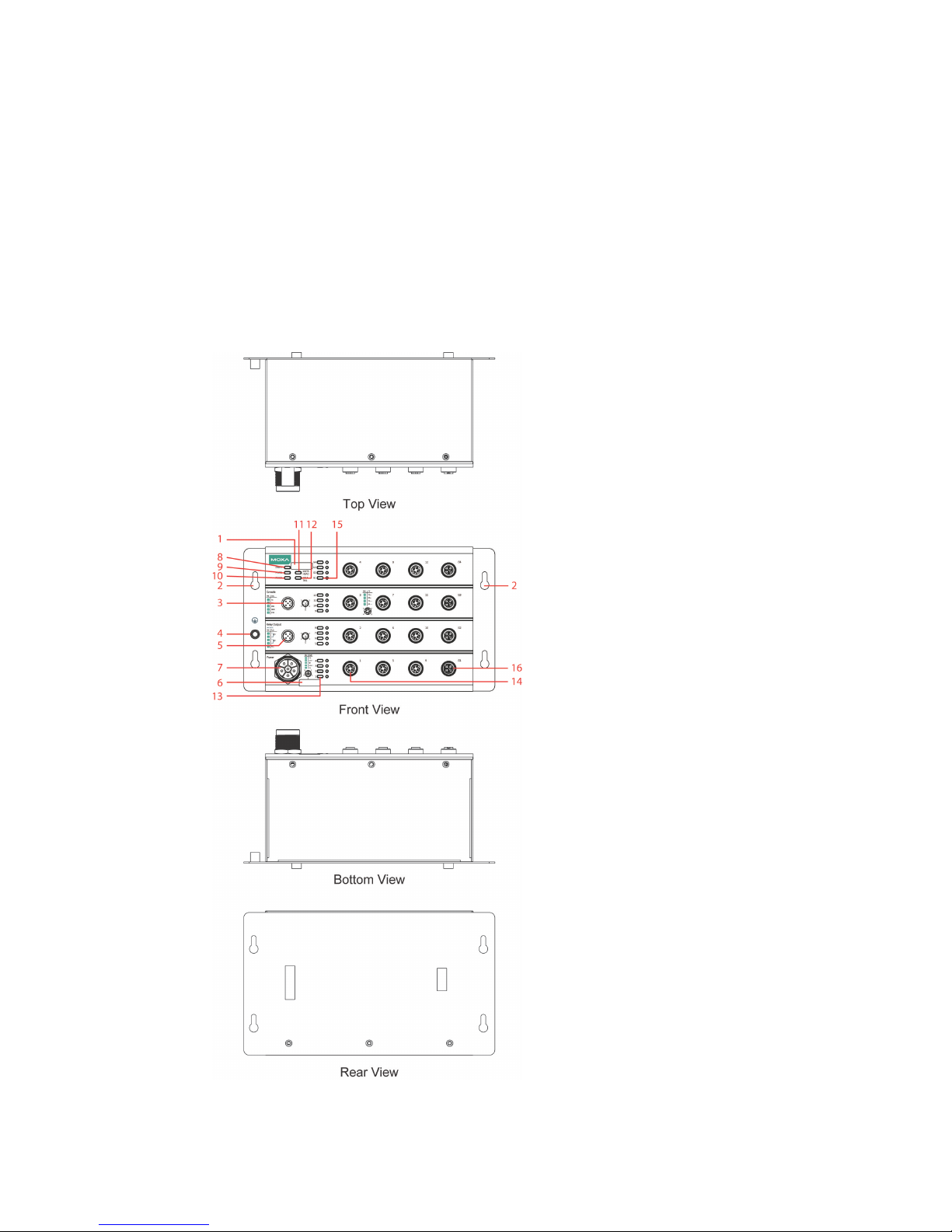
TN-4516A non-PoE Series Panel Layouts
1. Model name
2. Screw holes for panel
mounting kit
3. Console port
4. Grounding screw
5. Relay output port
6. Power input voltage
range indicator
7.
Power input port (male
5-pin shielded M23
connector)
8. PWR1 LED: for power
input 1
9. PWR2 LED: for power
input 2
10.
FAULT LED
11.
MSTR/HEAD LED: for
ring master or chain
head
12.
CPLR/TAIL LED: for
ring coupler or chain
tail
13. TP port’s 10/100 Mbps
LED
14.
10/100BaseT(X) port
(M12 D-coded 4-pin
female connector)
15.
Gigabit Ethernet port
LED: Gigabit port's
10/100/1000 Mbps
LED
16. 10/100/1000BaseT(X)
port (M12 X-coded
8-pin female
connector)
Page 5
- 5 -
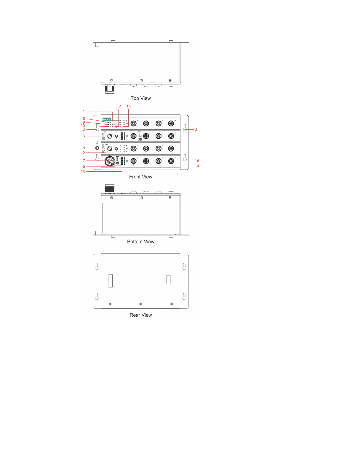
TN-4516A PoE Series Panel Layouts
1. Model name
2. Screw holes for panel
mounting kit
3. Console port
4. Grounding screw
5. Relay output port
6. Power input voltage
range indicator
7.
Power input port (male
5-pin shielded M23
connector)
8. PWR1 LED: for power
input 1
9. PWR2 LED: for power
input 2
10.
FAULT LED
11.
MSTR/HEAD LED: for
ring master or chain
head
12.
CPLR/TAIL LED: for
ring coupler or chain
tail
13. TP port’s 10/100 Mbps
LED
14.
10/100BaseT(X) port
(M12 D-coded 4-pin
female connector)
15.
Gigabit Ethernet port
LED: Gigabit port's
10/100/1000 Mbps
LED
16. 10/100/1000BaseT(X)
port (M12 X-coded
8-pin female
connector)
Page 6
- 6 -
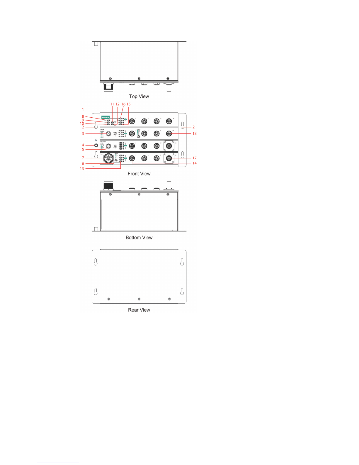
TN-4516A Fiber Series Panel Layo uts
1. Model name
2. Screw holes for panel
mounting kit
3. Console port
4. Grounding screw
5. Relay output port
6. Power input voltage
range indicator
7.
Power input port (male
5-pin shielded M23
connector)
8. PWR1 LED: for power
input 1
9. PWR2 LED: for power
input 2
10.
FAULT LED
11.
MSTR/HEAD LED: for
ring master or chain
head
12.
CPLR/TAIL LED: for
ring coupler or chain
tail
13. TP port’s 10/100 Mbps
LED
14.
10/100BaseT(X) port
(M12 D-coded 4-pin
female connector)
15.
Gigabit Ethernet port
LED: Gigabit port’s
1000 Mbps LED
16.
Gigabit Ethernet port
LED: Gigabit port’s
10/100/1000 Mbps
LED
17.
1000BaseLSX Gigabit
fiber port
18.
10/100/10
00BaseT(X)
port (M12 X-coded
8-pin female
connector)
Page 7
- 7 -
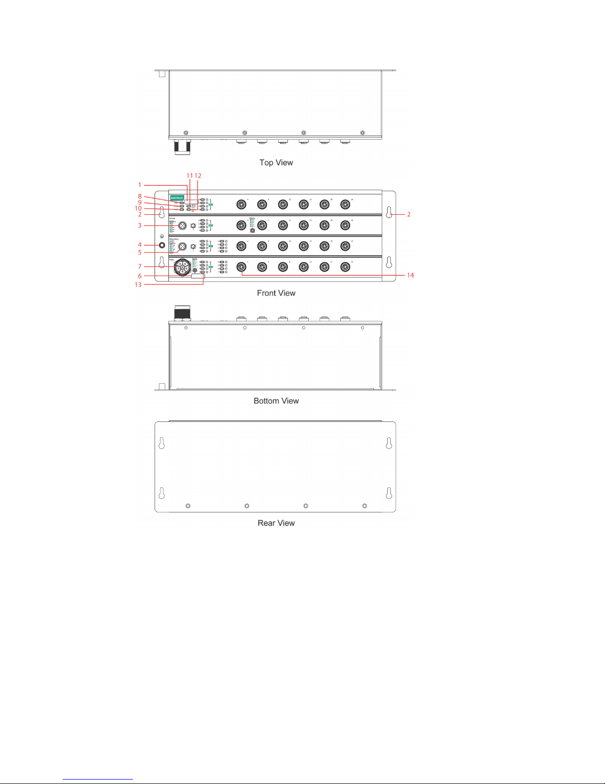
TN-4524A PoE Series Panel Layouts
1. Model name
2. Screw holes for panel mounting kit
3. Console port
4. Grounding screw
5. Relay output port
6. Power input voltage range indicator
7. Power input port (male 5-pin shielded M23 connector)
8. PWR1 LED: for power input 1
9. PWR2 LED: for power input 2
10. FAULT LED
11. MSTR/HEAD LED: for ring master or chain head
12. CPLR/TAIL LED: for ring coupler or chain tail
13. TP port’s 10/100 Mbps LED
14. 10/100BaseT(X) port (M12 D-coded 4-pin female connector)
Page 8

- 8 -
TN-4528A PoE Series Panel Layouts
1. Model name
2. Screw holes for panel mounting kit
3. Console port
4. Grounding screw
5. Relay output port
6. Power input voltage range indicator
7. Power input port (male 5-pin shielded M23 connector)
8. PWR1 LED: for power input 1
9. PWR2 LED: for power input 2
10. FAULT LED
11. MSTR/HEAD LED: for ring master or chain head
12. CPLR/TAIL LED: for ring coupler or chain tail
13. TP port’s 10/100 Mbps LED
14. 10/100BaseT(X) port (M12 D-coded 4-pin female connector)
15. Gigabit Ethernet port LED: Gigabit port’s 10/100/1000 Mbps LED
16. 10/100/1000BaseT(X) port (M12 X-coded 8-pin female connector)
Page 9

- 9 -
TN-4528A Fiber Series Panel Layo uts
1. Model name
2. Screw holes for panel mounting kit
3. Console port
4. Grounding screw
5. Relay output port
6. Power input voltage range indicator
7. Power input port (male 5-pin shielded M23 connector)
8. PWR1 LED: for power input 1
9. PWR2 LED: for power input 2
10. FAULT LED
11. MSTR/HEAD LED: for ring master or chain head
12. CPLR/TAIL LED: for ring coupler or chain tail
13. TP port’s 10/100 Mbps LED
14. 10/100BaseT(X) port (M12 D-coded 4-pin female connector)
15. Gigabit Ethernet port LED: Gigabit port’s 1000 Mbps LED
16. Gigabit Ethernet port LED: Gigabit port’s 10/100/1000 Mbps LED
17. 1000BaseLSX Gigabit fiber port
18. 10/100/1000BaseT(X) port (M12 X-coded 8-pin female connector)
Page 10

- 10 -
ATTENTION
Exposed connectors when not in use must be tightly covered w ith
protective caps (an optional accessory) to ensu re IP42
-rated
protection.
Mounting Dimensions (unit = mm)
TN-4516A non-PoE Series/TN-4516A PoE Series
Page 11

- 11 -
TN-4516A Fiber Series
Page 12

- 12 -
TN-4524A PoE Series
TN-4528A PoE Series
Page 13

- 13 -
TN-4528A Fiber Series
Panel/Wall Mounting
STEP 1: Mounting the TN-4500A to a wall requires 4 screws. Use the
ToughNet s witch as a guide to mark the correct positions of the 4 screws .
STEP 2: Use the 4 screws in the
panel mounting kit. If you would like
to use your own screws, make sure
the screw head
is
between 6.0 mm
and 7.0 mm
in diameter and the
shaft
is less than 4.0 mm in
diameter, as shown
at the right.
Do not screw the screws in all the way—leave a space of about 2 mm to
allow room for sliding the ToughNet switch between the wall and the
screws.
NOTE
Before tightening the screws into the wall, make sure the screw
head and shaft size are suitable by inserting the screw through
one of the keyhole-shaped apertures of the ToughNet switch.
STEP 3: Once the screws are fix ed in the wall, hang the ToughNet switch
on the 4 screws through the large opening of the keyhole-shaped
apertures, and then slide the switch downwa rds. Tighten t he four sc rews
for added stability.
Page 14

- 14 -
NOTE
To provide greater protection from vibration and shock, use
screws with shaft diameter between 6.0 mm and 7.0 mm, and fix
the ToughNet switch onto the wall directly through the large
opening of the keyhole-shaped apertures.
NOTE
TN-4500A series switches have passed IP42 certification. To
achieve the IP42 protection,
only use upright panel/wall
mounting
installation. Water sprayed at an angle of up to 15°
degrees from the vertical
will not damage the product (as
indicated in the following illustration).
Wiring Requirements
WARNING
Turn the power off
before disconnecting modules or wires. The
correct power supply voltage is listed on the product label. Check
the voltage of your power source to make s ure you are using th e
correct voltage. Do NOT use a voltage greater than what is
specified on the produc
t label.
These devices must be supplied by a SELV source as defined in
the Low Voltage Directive 2006/95/EC and 2004/108/EC.
Page 15

- 15 -
ATTENTION
Safety First!
Be sure to disconnect the power cord before installing and/or
wiring your Moxa switch.
This device has UL 61010-2-201
approval. Use copper conductors only, 75°C, and tighten to 4.5
pound-inches. For use in pollution degree 2 environment s .
ATTENTION
Safety First!
Observe all electric
al codes dictating the maximum current
allowable for each wire size. If the current
goes above the
maximum ratings, the wiring could overheat,
causing serious
damage to your equipment.
Please read and follow these guidelines:
• Use separate paths to route wiring for power and devices. If power
wiring and device wiring paths must cross, make sure the wires are
perpendicular at the intersection point.
NOTE: Do not run signal or communicat ions wiring and power wiring
through the same wire conduit. To avoid interfer ence, wires with
different signal characteristics should be routed separately.
• You can use the type of signal transmitted through a wire to
determine which wires should be k ept separat e. The ru le of thumb is
that wiring that shares similar electrical characteristics can be
bundled together.
• Keep input wiring and output wiring separated.
• It is strongly advised that you label wiring for all devices in the system
when necessary.
Grounding the ToughNet Switch
Grounding and wire routing help limit the effects of noise due to
electromagnetic interference (EMI). Run the groun d connect ion from th e
grounding screw to the grounding surface prior to connecting devices.
Page 16

- 16 -
ATTENTION
This product is intended
to be mounted to a well-grounded
mounting surface such as a metal panel.
Connecting the Power Supplies
ToughNet TN-4500A series switches support dual power inputs—power
input 1 and power input 2. The M23 6-pin male connector on the
TN-4500A series switches' front panel is used for the dual power inputs.
Pinouts for the power input port on the TN-4500A series
Pin
Description
Usage
1 PWR1 / DC +
Connect “PWR1 Live / DC +” to the positive (+)
terminal when using a DC power source.
2 PWR1 / DC -
Connect “PWR1 Neutra l / DC -” to the negative (-)
terminal when using a DC power source.
3 Chassis Ground
Connect the “Chassis Ground” to the equipment
ground bus for DC inputs.
4 PWR2 / DC -
Connect “PWR2 Neutra l / DC -” to the negative (-)
terminal when using a DC power source.
5 PWR2 / DC +
Connect “PWR2 Live / DC +” to the positive (+)
terminal when using a DC power source.
STEP 1: Plug your power cord connector int o the power input port of the
TN-4500A switch.
STEP 2: Screw the nut on your power cord connect or into the power input
connector on the switch to ensure a tight connection.
ATTENTION
Before connecting the TN-4500A series to the power input, make
sure the power source voltage is stable.
ATTENTION
Do not power on
the TN-4500A series before connecting the
M23
connector.
Page 17

- 17 -
Connecting the Relay Outputs
Each TN-4500A series switch has two sets of relay outputs—relay output
1 and relay output 2. The M12 A-coded 5-pin male connector on the
TN-4500A series’ front panel is used for the two relay outputs. Use a
power cord with an M12 A-coded 5-pin female connector to connect the
relay contacts. You can purchase an M12 power cable from Moxa; the
model number is CBL-M12 (FF5P)/OPEN-100 IP67.
Pinouts for the relay output port on the TN-4500A series
N.C.: Not connected
FAULT:
The two sets of relay contacts of the M12 A-coded 5-pin male connector
are used to detect user-configured events. The two wires attached to the
fault contacts form an open circuit when a user-con figured event is
triggered. If a user-configured event does not occur, the fault circuit
remains closed.
Connecting the Data Lines
10/100BaseT(X) Ethernet Port Connection
All TN-4500A series models have 12 or 24 10/100BaseT(X) Ethernet ports
(M12 D-coded 4-pin female connector). The 10/100TX ports located on
the TN-4500A series front pane l are used to connect to Ethernet-enabled
devices. Most users configure these ports for Auto MDI/MDI-X mode, in
which case the port’s pinouts are adjusted automatically depending on
the type of Ethernet cable used (s traight-through or cross-over), and the
type of device (NIC-type or HUB/Switch-type) connected to the port.
In what follows, we give pinouts for both MDI (NIC-type) ports and MDI-X
(HUB/Switch-type) ports. We also giv e c able wiring diagrams for
straight-through and cross-over Ethernet cables.
Pinouts for the 10/100BaseT(X) Ports on the TN-4500A series
Housing: shield
Page 18

- 18 -
Pinouts for the 10/100/1000BaseT(X) M12 (8-pin) Port
Pinouts for the 1000BaseLSX Q-ODC® Gigabit Fiber port
Mating Sequence
Push plug slightly into
connector socket
Rotate to find keying
position
Unmated – push
connector to mate
Mated – connector
snaps in and is fully
strain relieved
Pull coupling ring to
unmate
M12 (4-pin, M) to M12 (4-pin, M) Cross-Over Cable Wiring
M12 (4-pin, M) to M12 (4-pin, M) Straight-Trough Cable Wiring
Page 19

- 19 -
M12 (4-pin, M) to RJ45 (8-pin) Cross-Over Cable Wiring
M12 (4-pin, M) to RJ45 (8-pin) Straight-Trough Cable Wiring
M12 (8-pin, M) to M12 (8-pin, M) Cross-Over Cable Wiring
Page 20

- 20 -
M12 (8-pin, M) to M12 (8-pin, M) Straight-Trough Cable Wiring
M12 (8-pin, M) to RJ45 (8-pin) Cross-Over Cable Wiring
M12 (8-pin, M) to RJ45 (8-pin) Straight-Trough Cable Wiring
Page 21

- 21 -
ATTENTION
The protective cover must be fixed properly to ensure IP
42
protection. Use a torque wrench set to a torque of 4 kgf-m when
tightening the screws. Note that applying a larger torque may
damage the plastic protective cover.
LED Indicators
Several LED indicators are located on the ToughNet sw itch’s front pa ne l.
The function of each LED is described in the tabl e below.
LED
Color
State
Description
System LEDs
PWR1 AMBER
ON
Power is being supplied to power input
PWR1.
OFF
Power is not being supplied to power input
PWR1
PWR2 AMBER
ON
Power is being supplied to power input
PWR2.
OFF
Power is not being supplied to power input
PWR2.
FAULT RED
ON
When the corresponding PORT alarm is
enabled, and a user-configured event is
triggered.
OFF
When the corresponding PORT alarm is
enabled and a user-configured event is
not triggered, or when the corresponding
PORT alarm is disabled.
MSTR/
HEAD
GREEN
ON
When the TN switch is either the Ma ster of
this Turbo Ring, or the Head of this Turbo
Chain.
Blinking
When the TN switch is Ring Master of this
Turbo Ring and the Turbo Ring is broken,
or it is the
Chain Head of this Turbo Chain
and the Turbo Chain is broken.
OFF
When the TN switch is neither the Master
of this Turbo Ring, nor the Head of this
Turbo Chain.
CPLR/
TAIL
GREEN
ON
When the TN switch enables the coupling
function to form a back-up path in this
Turbo Ring, or it is the Tail of this Turbo
Chain.
Blinking
When Turbo Chain is down.
OFF
When the TN switch disables the coupling
function of Turbo Ring, or it is not the Tail
of the Turbo Chain.
Port LEDs
TP
(10/
100M)
AMBER
ON
TP port’s 10 Mbps link is active.
Blinking
Data is being transmitted at 10 Mbps.
OFF
TP port’s 10 Mbps link is inactive.
GREEN
ON
TP port’s 100 Mbps link is active.
Blinking
Data is being transmitted at 100 Mbps.
OFF
TP port’s 100 Mbps link is inactive.
Page 22

- 22 -
LED
Color
State
Description
PoE Ports AMBER
ON
Power is being supplied to a Powered
Device (PD)
OFF
Power is not being supplied to a Powered
Device (PD)
G1 to G4
(10/100/
1000M,
for copper
ports)
AMBER
On
TP port’s 10 or 100 Mbps link is active.
Blinking
Data is being transmitted at 10 or 100
Mbps.
OFF
TP port’s 10 or 100 Mbps link is inactive.
GREEN
ON
TP port’s 1000 Mbps link is active.
Blinking
Data is being transmitted at 1000 Mbps.
OFF
TP port’s 1000 Mbps link is inactive.
G1/G2
(1000M, for
fiber ports)
GREEN
ON
TP port’s 1000 Mbps link is active.
Blinking
Data is being transmitted at 1000 Mbps.
OFF
TP port’s 1000 Mbps link is inactive.
Specifications
Technology
Standards
IEEE 802.3 for 10BaseT
IEEE 802.3u for 100BaseT(X)
IEEE 802.3ab for 1000BaseT(X)
IEEE 802.3x for Flow Control
IEEE 802.1D for Spanning Tree Protocol
IEEE 802.1w for Rapid STP
IEEE 802.1Q for VLAN Tagging
IEEE 802.1s for Multiple Spanning Tree Protocol
IEEE 802.1p for Class of Service
IEEE 802.1X for Authentication
IEEE 802.3ad for Port Trunk with LACP
Software Features
Management
IPv4/IPv6, SNMP v1/v2c/v3, Telnet, LLDP, Port
Mirror, Syslog, RMON, BootP, DHCP Server/Client,
DHCP Option 66/67/82, TFTP, SNTP, SMTP, RARP,
HTTP, HTTPS, SNMP inform, Flow Control, Bac k
pressure flow control
Filter 802.1Q VLAN, Port-
Based VLAN, GVRP, IGMPv1/v2,
GMRP, Static Multicast
Redundancy
Protocols
STP/RSTP, MSTP, Turbo R i n g v1/v2, Turbo Ring v2
with DRC, Turbo Chain, Link Aggregation
Security
RADIUS, TACACS+, SSL, SSH, Port Lock, Broadcast
Storm Protection, Rate Limit
Time Management
SNTP, NTP Server/Client, IEEE 1588v2
PTP(SW-based)
MIB
MIB-II, Ethernet-like MIB, P-BRIDGE MIB,
Q-BRIDGE MIB, Bridge MIB, RSTP MIB, RMON MIB
Group 1, 2, 3, 9
Switch Properties
Priority Queues
4
Max. Number of
Available VLANs
64
VLAN ID Range
VID 1 to 4094
IGMP Groups
256
Page 23

- 23 -
Interface
Fast Ethernet
Front cabling, M12 D-coded 4-pin female connector,
10/100BaseT(X) auto negotiation speed, F/H duplex
mode, and auto MDI/MDI-X connection
Gigabit Ethernet Copper ports: M12 X-coded 8-
pin female connector,
10/100/1000BaseT(X) and bypass relay option
Fiber ports: M12 connector, 1000BaseLSX
Console Port
M12 A-coding 5-pin male connector
System LED
Indicators
PWR1, PWR2, FAULT, MSTR/HEAD, CPLR/TAIL
Port LED Indicators 10/100M (Fast Ethernet port), 10/100/1000M
(Gigabit Ethernet port), PoE
Alarm Contact
Two relay outputs in one M12 A-coding 5-pin male
connector with current carrying capacity of 1
A @ 30
VDC
Power Requirements
Input Voltage
24/36/48/72/96/110 VDC
Operating Voltage
16.8 to 137.5 VDC
Input Current
TN-4516A non-PoE series: Max. 0.7 A @ 24 VDC
TN-4516A PoE series: Max. 7.0 A @ 24 VDC
TN-4516A fiber series: Max. 7.0 A @ 24 VDC
TN-4524A PoE series: Max. 6.5 A @ 24 VDC
TN-4528A PoE series: Max. 7.2 A @ 24 VDC
TN-4528A fiber series: Max. 7.2 A @ 24 VDC
Connection
M23 6-pin male connector
Overload Current
Protection
Present
Reverse Polarity
Protection
Present
Physical Characteristics
Housing
Metal
IP Rating
IP42 protection (optional protective caps available
for unused ports)
Dimensions
(W × H × D)
TN-4516A non-PoE series:
229.8 x 132 x 122.3 mm (9.05 x 5.20 x 4.81 in)
TN-4516A PoE series:
229.8 x 132 x 122.3 mm (9.05 x 5.20 x 4.81 in)
TN-4516A fiber series:
229.8 x 132 x 122.3 mm (9.05 x 5.20 x 4.81 in)
TN-4524A PoE series:
347.8 x 132 x 122.3 mm (13.70 x 5.20 x 4.81 in)
TN-4528A PoE series:
347.8 x 132 x 122.3 mm (13.70 x 5.20 x 4.81 in)
TN-4528A fiber series:
347.8 x 132 x 122.3 mm (13.70 x 5.20 x 4.81 in)
Weight
TN-4516A non-PoE series: 1965 g (4.32 lb)
TN-4516A PoE series: 2607 g (5.74 lb)
TN-4516A fiber series: 2705 g (5.96 lb)
TN-4524A PoE series: 3063 g (6.74 lb)
TN-4528A PoE series: 3304 g (7.27 lb)
TN-4528A fiber series: 3375 g (7.44 lb)
Installation
Panel mounting
Page 24

- 24 -
Environmental Limits
Operating
Temperature
-40 to 75°C (-40 to 167°F)
Storage
Temperature
-40 to 85°C (-40 to 185°F)
Operating Humidity
5 to 95% (non-condensing)
Regulatory Approvals
Safety
UL 61010-2-201 (Pending), EN 60950-1 (LVD)
EMC
EN 55032, EN 55024
EMI
CISPR 32, FCC Part 15B Class A
EMS
IEC 61000-4-2 ESD: Contact: 6 kV; Air: 8 kV
IEC 61000-4-3 RS: 80 MHz to 1 GHz: 20 V/m
IEC 61000-4-4 EFT: Power: 2 kV; Signal: 2 kV
IEC 61000-4-5 Surge: Power: 2 kV; Signal: 2 kV
IEC 61000-4-6 CS: 10 V
IEC 61000-4-8
Rail Traffic
(for panel mounting installations)
EN 50155*, EN 50121-4, EN 45545-2
*This product is suitable for rolling stock railway applications, as de fined
by the EN 50155 standard. For a more detailed statement, click here:
www.moxa.com/doc/specs/EN_50155_Compliance.pdf
Shock
EN 50155, IEC 61373
Freefall
IEC60068-2-31
Vibration
EN 50155, IEC 61373
Please check Moxa’s website for the most up-to-date certification status.
MTBF (mean time between fai l ur es )
Time
TN-4516A-4GTX-WV-T: 599,164 hrs.
TN-4516A-4GTXBP-WV-T: 589,421 hrs.
TN-4516A-12PoE-4GPoE-WV-T: 428,680 hrs.
TN-4516A-12PoE-2GPoE-2GTXBP-WV-T: 427,322 hrs.
TN-4516A-12PoE-2GPoE-2GODC-WV-T: 421,432 hrs.
TN-4524A-16PoE-WV-T: 429,402 hrs.
TN-4528A-16PoE-4GPoE-WV-T: 393,894 hrs.
TN-4528A-16PoE-2GPoE-2GTXBP-WV-T: 392,746 hrs.
TN-4528A-16PoE-2GPoE-2GODC-WV-T: 387,767 hrs.
Standard
Telcordia SR332
Regulatory Approvals
Warranty Period
5 years
Details
See www.moxa.com/warranty
 Loading...