

Page 1
If you use DB9 for an RS-485/422 cable connection, the Pin
definition and assignments are as follows:
• RESISTOR SW
(Terminal Resistor/Pull-up and Pull-Down Res. Setting)
You may configure RESISTOR SW for proper termination or
P-UP, P-DOWN resistors for the network connection.
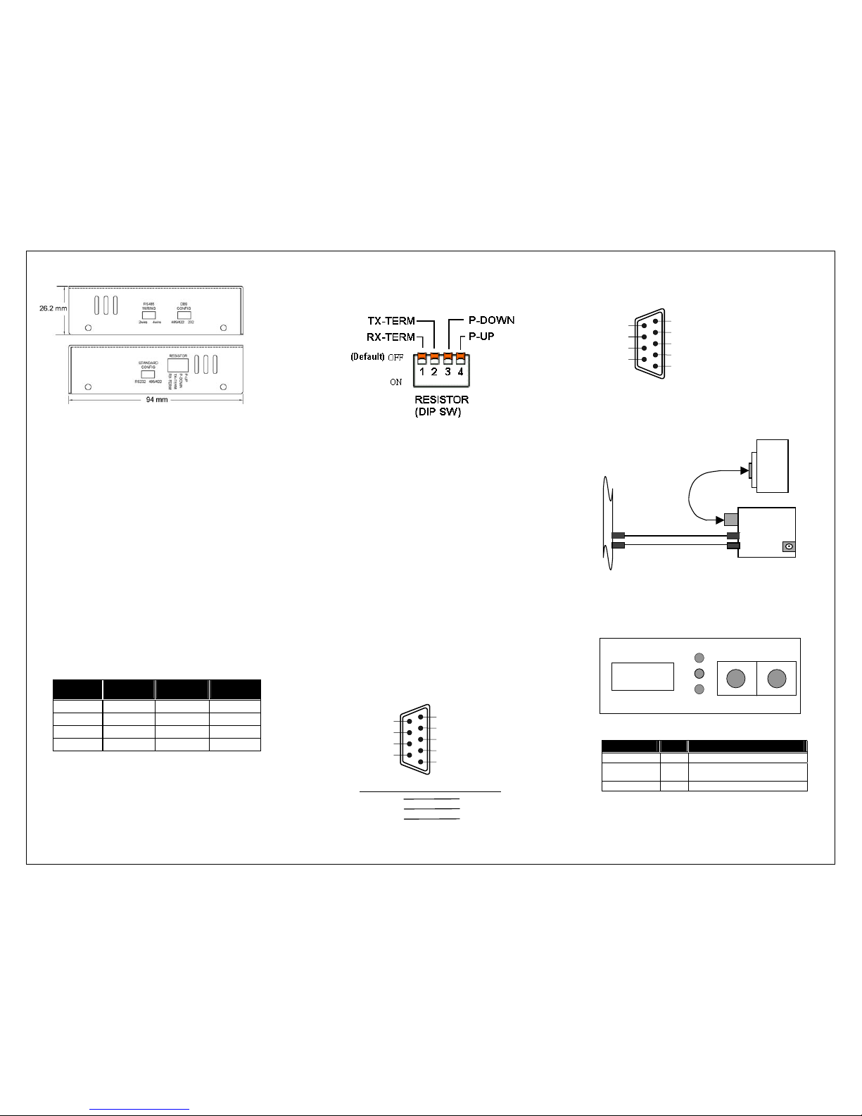
Fig. 2: DB9 to Fiber Converter Side Panels
The RESISTOR SW is used for RS-485/422 protocol/connection,
and takes effect when STANDARD CONFIG is at "485/422".
2. Switch Settings
The two side panels of the Converter contain a total of four sets
of DIP Switches (abbreviated SW)—labeled RS485 WIRING,
DB9 CONFIG, STANDARD CONFIG, and RESISTOR—that
are used to configure the various data transmission modes. The
proper configuration of each of these four sets of DIP Switches
is described below:
RESISTOR SW default: 1, 2, 3, 4. All are at "OFF"
RX-TERM ON: Enables 130Ω terminator on RX
TX-TERM ON: Enables 130Ω terminator on TX
P-DOWN ON: Enables 1 KΩ pull down on
RS422 TXor
RS485(2-wire)TX/RX-
• STANDARD CONFIG
For selecting serial port protocol: RS-232 or RS-485/422.
P-UP ON : Enables 1 KΩ pull up on
RS422 TX+ or
RS485(2-wire)TX/RX+
RS232: RS-232 protocol/connection, default.
485/422: RS-485/422 protocol/connection.
• RS485 WIRING
Note:
For selecting between 2-wire and 4-wire RS-485.
The way in which the termination and P-UP, P-DOWN resistors
are set up depends on the RS-485/422 network configuration.
2wire: 2-wire at half-duplex mode.
4wire: 4-wire at full-duplex mode, default.
• DB9 CONFIG
• Ensure that the copper cable and its voltage polarity match
the device requirements for a 4-wire or 2-wire connection.
232: RS-232/DB9 connection, default.
485/422: RS-485/422 via DB9 port
• Improper termination and network configuration will cause
the devices to work poorly.
NOTE: The STANDARD CONFIG and DB9 CONFIG DIP
Switch settings must agree. Either set both to RS-232, or set
both to RS-485/422.
3. LED Description
• When thee Rx-TERM & TX-TERM switches are enabled,
both P-Down & P-Up DIP switches should be on as well.
For DB9 model and port connection, the available
connections by the three SW settings are:
• DB9 Connector for Copper Wires
Protocol &
Connection
STANDARD
CONFIG SW
DB9 CONFIG
SW
RS485
WIRING SW
RS-232 RS232 232 ---
4-wire RS-485 485/422 485/422 4wire
2-wire RS-485 485/422 485/422 2wire
RS-422 485/422 485/422 4wire
RS-232 protocol/connection via DB9
LED Color Function
F (FX ACT) Green Blinks when fiber data is received
C (Copper ACT) Green
Blinks when Copper data is
received
PWR Green
Lit when +5V power is coming up
RS-232 Cable Connection via DB9
RXD
2 3 TXD
TXD 3 2 RXD
GND 5 5 GND
RS-485/422 protocol/connection via DB9
1 RS-485/422 TX- or RS-485(2-wire) TX/RX-
2 RS-485/422 TX+ or RS-485(2-wire)TX/RX+
3 RS-485/422 RX+
4 RS-485/422 RX-
5 Signal Ground
Unused 6
Unused 7
Unused 8
Unused 9
Fig. 6: RS-485/422/232 to ST Fiber Converter Front Panel
Optic Fiber Port
TX RX
PWR
F
A
CT
RS-485/422/232
Fiber Media Converter
C
DB9 or
Terminal Block
RS485/422/232 Port
Fig. 5: RS-485/422/232 Fiber Optic Network Connection
RS-232
RS-422
RS-485
DB9 or
Terminal
Block
Fiber Optic Wire
RX
TX
RS-485/422/232
DB9, Terminal
Fiber Converter
RX
TX
Copper Wire
1 Unuse
d
2 RS-232 RXD
3 RS-232 TXD
4 Unuse
d
5 Signal Ground
Unused 6
Unused 7
Unused 8
Unused 9
Page 2

4. DC Jack and AC-DC Power Adapter
The DC jack's central post is 2.5 mm wide and conforms to the
dimensions of the DC receptacle (2.5 mm).
AC-DC adapters that use different AC input voltages are available
for different areas.
North America 120VAC 60Hz
Europe 230VAC 50Hz
U.K. 230VAC 50Hz
South Africa 240VAC 50Hz
Australia 240VAC 50Hz
AC Input:
Japan 100VAC 50/60Hz
DC Output: 5VDC @ 1.0A
5. Fiber Technical Specifications
• Standards: TIA/EIA-232(ITU-T V.28)
TIA/EIA-422(ITU-T V.11)
TIA/EIA-485(ISO/IEC8284)
• Model Description:
Model Interface Fiber Type
λ(nm)
Distance
TCF-141-M DB9(male) ST multi-mode 820 2Km
TCF-141-S DB9(male)
ST single-
mode
1310
20Km
• Data Transfer Rate and Maximum Cable Distance
Connection Max. Rate (bps) Max. Distance
RS-232 115.2K 15 m (50 ft)
RS-422/485 90K 1220 m (4000 ft)
RS-422/485 500K 92 m (300 ft)
Multi-Mode Fiber * 2 km
Single-Mode Fiber * 20 km
* Fiber Optic Rate depends on the Copper Port speed
• Copper Wires: 24 to 22 AWG gauge
Attenuation 20dB/1000ft @ 10 MHz
Differential Impedance 100Ω @ 10 MHz
• Fiber Cable:
50/125, 62.5/125, or 100/140
µ
m multi-mode
8.3/125, 8.7/125, 9/125, or 10/125
µ
m single-mode
• Data Transfer Rate: up to 115.2 Kbps (RS-232)
up to 500 Kbps (RS-485/422)
• Power Requirement: 1A@+5 VDC
• Ambient Temperature: 0 to 50°C
• Humidity: 5 to 90% RH
• Dimensions: 26.2(H) × 70.3(W) × 94(D) mm
• Complies with FCC Part 15 Class B and CE Mark
Note:
When connecting this device to a Router, Bridge or Switch,
please refer to the corresponding device's Technical Manual for
detailed technical information.
Moxa Technologies Co., Ltd.
Tel: +866-2-8919-1230
Fax: +886-2-8919-1231
www.moxa.com
support@moxa.com.tw
2nd Edition
P/N: 18020014101
TCF-141-S, TCF-141-M
RS-485/422/232 to Fiber Converter
(DB9 to ST Fiber)
User's Manual
1. Overview
RS-485/422/232 to fiber optic converters are used to extend
serial transmission distance up to 2 km (using multi-mode fiber)
or up to 20 km (using single-mode fiber). The TCF-141-S (TCF141-M) Converter is equipped with a multiple interface circuit
that can handle RS-232, RS-422, and RS-485 serial interfaces.
6. Package Checklist
Before installing the Converter, verify that the package contains
the following items:
• The RS-485/422/232 to Fiber Converter
• AC-DC Power Adapter
• This User's Manual
Notify your sales representative immediately if any of the above
items is missing or damaged.
7. Installing the Converter
Note: The Media Converter is hot-swappable.
• Wear a grounding device for electrostatic discharge.
• Verify that the AC-DC adapter conforms to your country’s
AC power requirement and then insert the power plug.
• Install the media cable for network connection.
TCF-141-M
Fig. 1: RS-485/422/232 DB9 to Fiber Converter
DC Jack : 2.5mm
DC Input : +5V
(RS-C200
DC current: full load consumption 0.5A)
Fig. 7: DC+5V Input Jack and Dimensions
 Loading...