

Page 1
– 1 – – 2 – – 3 –
P/N: 1802061100010
TC-6110 Series
Train Computer
Quick Installation Guide
First Edition, Mar ch 2013
1. Overview
TC-6110 train computers are specifically designed for on-board
train applications. They come with 2 Gigabit LAN ports, 1 RS-232
serial port, 3 USB 2.0 hosts, and 2 expansion slots, offering an
ideal solution f or any auxiliary train application.
To guarantee high reliability an d availabilit y during train
operations, TC-6110 computers come with M12 connectors for
Gigabit LAN ports, USB ports, and dual power inputs. In addition,
the expansion mo dules offer hig h flexibility fo r system integr ation.
Users can e asily expand the system with additional storage
modules for greater storage capacity.
2. Model Names and Package Checklist
The TC-6110 Series in cludes the follow ing models:
• TC-6110-W7E: Modular 3 U/42HP train com puter, Intel Atom
D525 1.8GHz CPU, 4 expansion slots, 24 to 110 VDC isolated
power, Win7 Embedded (32-bit) , -25 to 55°C o perating
temperature range, compliant with EN 50155 T1
• TC-6110-T-W7E: Modular 3U/42HP train computer, Intel
Atom D525 1.8GHz CPU, 4 expansion slots, 24 to 110 VDC
isolated power, Win7 Embedded (32-bit), - 40 to 70°C
operating temperature range, compliant with EN 50155 TX
Each basic system model is shipped with following standard items:
• TC-6110 train computer
• Rackmount kit
• Documentation CD or DVD
• Quick installat ion guide (printed)
• Warranty card
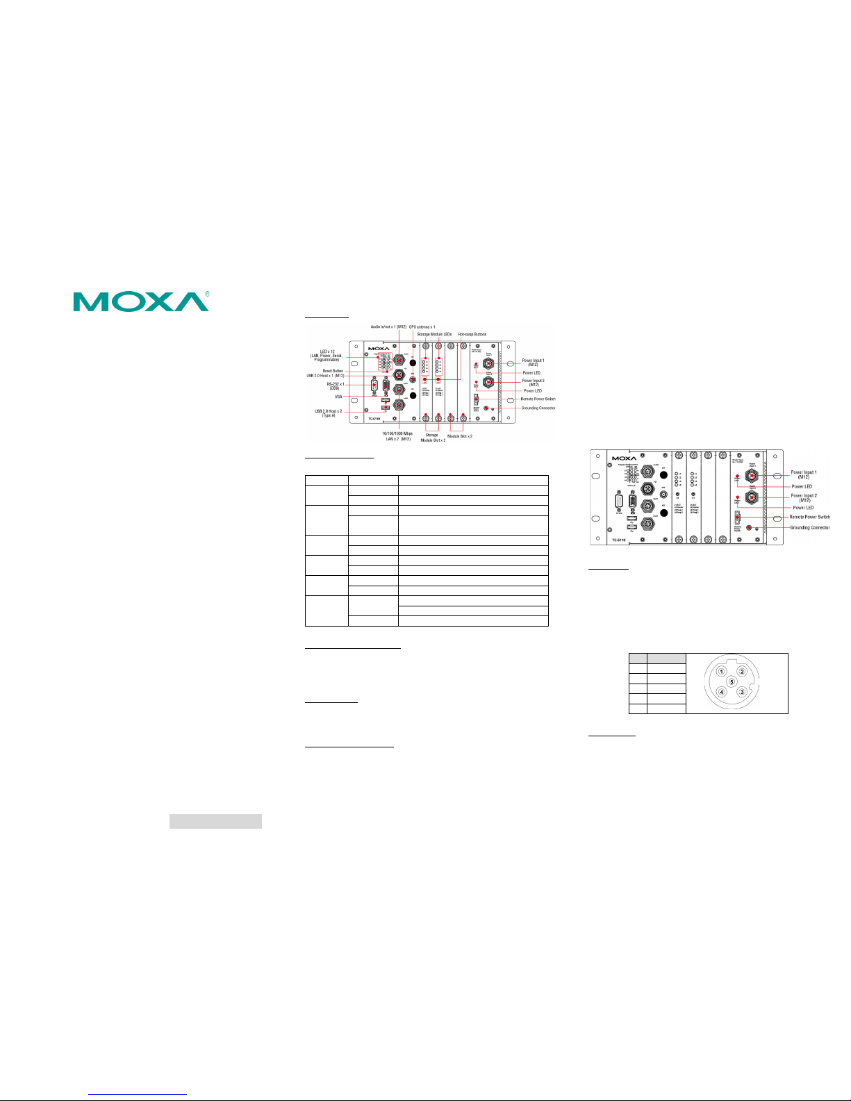
3. Hardware Installation
Front View
Front Panel LE Ds
Information ab out each LED is giv en in the follo wing table.
LED Name
LED Color
LED Functi on
Power
Green
Power is on an d functi oning norm ally
Off
Power off or powe r error exists
Syste m
Ready
Yellow
OS System login in and functioning normall y
Off OS System not login in or not functioning
normally
Tx(P1) Green Serial Port P1 transmitting data
Off Serial Port P1 not transmitting data
Rx(P1) Yellow Serial Port P1receving dat a
Off Serial Port P1n ot receivi ng data
X1-X4 Yellow Programmable by u sers
Off Programmable by u sers
LAN(P1-P2) Green
Yellow
100Mbps Ethernet link
1000Mbps Ethernet link
Off Disconnected or sh ort circuit
Connecting to a Display
The TC-6110 comes with a VGA interface via a D-Sub 15-pin
female connector on the front panel. To ensure that the monitor
image remains clear, be sure to tighten the monitor cable’s
thumbscrews after connecting it to the TC-6110.
Reset Button
Press the Reset Button on the front panel of the TC-6110 to reboot
the system automatically. The Ready LED will maintain a steady
glow once the system has rebooted.
Connecti ng the P ower
The TC-6110 offers two power inputs with 24 to 110 VDC. Both
come with M12 connectors.
To install the bundled power switch, users must first connect a
power controller—either switch or remote power relay—to the
provided Euroblock terminal (Phoenix connector) that is found
mounted on the TC-6110 faceplate. This may be done by directly
connecting the bundled accessory switch to the provided Euroblock
plug, by wiring the switch to the plug using a length of standard
gauge copper wire, or by wiring the terminal to a remote relay.
To connect the provided switch, fasten the two wires (hot and
neutral) to the provided terminal plug and insert the plug into the
faceplate socket. The switch may also be directly mounted to the
terminal plug. W hen wiring the te rminal to a remo te relay, “on” is
associated with a closed circuit, and “off” with an open circuit.
Once the switch is installed you may connect the power cable to
the power input. Re fer to the follo wing figure for detailed
information about the faceplate layout. If the power supply is
connected properly, the green Power LEDs and the system
Power LED (in the upper left corner of the faceplate) will be on, as
will the yellow Ready LED.
USB Ports
The TC-6110 embedded computer has three USB 2.0 ports; two
come with type A connectors, and one with an M12 connector. All
of the ports are UHCI, Rev 2.0 compliant and support Plug & Play
and hot swapping. These ports can be used to connect USB devices,
like keyboards, mouse interfac es, USB flash dis ks, and USB
CD-ROMs. In a ddition, BIOS configuration allows for system boot
from any USB port. See the followin g table and figu re for the pin
assignment of the USB host with M12 connector.
Pin
USB 1
D+ 2 D- 3 +5V 4 GND 5 N.C.
Note: N.C . means “Not c onnected”
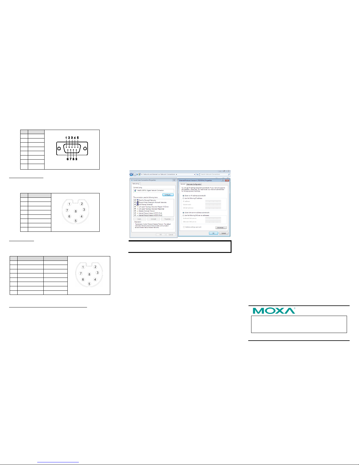
Serial Ports
The TC-6110 comes with one RS-232 serial po rt, over a DB9 male
connector. See the following figure for the location of the serial
port.
Page 2
– 4 – – 5 – – 6 –
www.moxa.com/support
The Americas:
+1-714-528-6777 (toll-free: 1-888-669-2872)
Europe:
+49-89-3 70 03 99-0
Asia-Pacific:
+886-2-8919-1230
China:
+86-21-5258-9955 (toll-free: 800-820-5036)
2013 Moxa Inc. All r ights reserved.
The pin assignments for the ports are shown in the following table:
Pin
RS-232
1
DCD 2 RxD 3 TxD
4
DTR
5
GND 6 DSR
7
RTS
8 CTS
Audio Input/Output
The TC-6110 Series comes with an audio input/output connector in
M12 connector. Use a cable to connector the audio input and
output. See the following figu re and table f or pin assignme nt.
Pin
Audio
1
Line in-Right
2
GND
3
-- 4 Line in-Left
5
Line out-Left
6
-- 7 Line out-Right
8
GND
Ethernet Ports
The TC-6110 has 2 10/100/1000 Mbps LAN ports with M12
connectors. When the cable is properly connected, the LEDs on the
front panel will g low to indicat e a successful connection.
Pin
10/100 Mbps
1000 Mbps
1 – TRD3+
2 – TRD4+
3 – TRD4-
4
ERx-
TRD1-
5
ETx+
TRD2+
6
ERx+
TRD1+
7 – TRD3-
8
ERx-
TRD2-
These LAN ports use DHCP for the IP address.
Installing the SSD/HDD into the Storage Tray
The TC-6110 computers come with 2 storage trays that can be
installed with SSD or HDD for storage expansion. Refer to
Hardware Manua l for detailed d escription fo r the installat ion.
4. Configuring the Ethernet Interface
Follow these steps to configure the Ethernet interface
Step 1: Go to Start=>Control Panel=>Network and
Internet=> Network Connections.
Step 2: In the screen of Local Area Connection Properties,
click Internet Protocol (TCP/IP) and then select
Properties.
Step 3: C lick OK after inputting the proper IP address and
netmask.
NOTE
Refer to the User’s Manual for additional configuration
information.
 Loading...