

Moxa Technologies TC-6110-CT-W7E, TC-6110-CT-T-W7E, TC-6110-LX, TC-6110-T-LX, TC-6110-CT-LX Quick Installation Manual
...Page 1

– 1 – – 2 – – 3 –
P/N: 1802061100011
TC-6110 Series
Train Computer
Quick Installation Guide
Second Edition, May 2013
1. Overview
TC-6110 train computers are specifically designed for onboard
train applications. They come with 2 Gigabit LAN ports, 1 RS-232
serial port, 3 USB 2.0 hosts, and 2 expansion slots, offering an
ideal solution f or any auxiliary train application.
To guarantee high reliability and availabilit y during train
operations, TC-6110 computers come with M12 connectors for
Gigabit LAN ports, USB ports, and dual power inputs. In addition,
the expansion mo dules offer hig h flexibility fo r system integr ation.
Users can easily expand the system with additional storage
modules for greater storage capacity.
2. Model Names and Package Checklist
The TC-6110 Series in cludes the follow ing models:
• TC-6110-W7E: Modular 3 U/42HP train com puter, Intel Atom
D525 1.8GHz CPU, 4 expansion slots, 24 to 110 VDC isolated
power, Win7 Embedded (32-bit), -25 to 55°C operating
temperature range, compliant with EN 50155 T1
• TC-6110-T-W7E: Modular 3U/42HP train computer, Intel
Atom D525 1.8GHz CPU, 4 expansion slots, 24 to 110 VDC
isolated power , Win7 Embedde d (32-bit), -40 to 70°C
operating temperature range, compliant with EN 50155 TX
Each basic system model is shipped with following standard items:
• TC-6110 train computer
• Rackmount kit
• Power switch with cable extender
• Power ca ble
• Documentation CD or DVD
• Quick installat ion guide (prin ted)
• Warranty card
3. Hardware Installation
Front View
Front Panel LEDs
Information ab out each LED is giv en in the follo wing table.
LED Name
LED Color
LED Functi on
Power
Green
Power is on an d functi oning norm ally
Off
Power i s off or power system error
Syste m
Ready
Yellow
Logged in to OS, functioning normally
Off
Login failure or OS not functioning normally
Tx (P1)
Green
Serial port P1 transmitting data
Off
Serial port P1 not transmitting data
Rx (P1)
Yellow
Serial port P1receving data
Off
Serial port P1 not receiving data
X1-X4
Green
Programmable by u sers
Off
Programmable by u sers
LAN (P1-P2)
Green
Work in g 100 Mbps Ethernet link
Yellow
Work in g 1000 Mbps Ethernet l ink
Off
Disconnected or sh ort circuit
Connecting to a Display
The TC-6110 comes with a female D-Sub DE-15 VGA interface on
the front panel. To ensure that the monitor image remains stable,
be sure to tighten the connector’s thumbscrews after connecting
the cable.
Reset Button
The reset button on the TC-6110’s front panel initiates a so ft
system re boot. Once the system h as completed the reboot the
Ready LED will maintain a steady glow.
Powering t he TC-6110
TC-6110 computers come with DC power inputs. When connecting
the TC-6110 to an office AC source (for test ing), an adaptor must
be used. To connect the AC adaptor, follow these steps:
Step 1: Connect the ends of the extended power switch cable to
the male portio n of the 2-pin Euroblock (provided).
Step 2: Plug the male Euroblock into the matching female terminal
on the front panel.
Step 3: Make sure the power switch is turned off (Open, in the
diagram below) .
Step 4: C onnect the e arth/ground cable to the Phillips-head
ground connector on the lower right corner of the front panel.
Step 5: Connect the power cable
(CBL-Power Jack to M12) to the M12
connector as shown at right. Then
connect the power connector to
power input 1 on the front panel.
Step 6: On the other side of the power cable, connect to the
PWR-24250-DT-S1 power adaptor (optional), and a PWC-series
power cord (optional).
Step 7: To ch eck power redundancy, use the same method to
connect the power to the power input 2.
Step 8: S witch on the TC- 6110 (Short state). If power supply is
connected properly, both power input and system power LEDs will
be on (green) , as well as the yellow Ready LED .
When installing TC-6110 computers at a field site , follow these
steps:
Step 1: Conne ct the ends of the extended power switch cable to
the male portio n of the 2-pin Euroblock (provided); you may also
choose to not use the cable extender, and connect the switch to
the terminal dire ctly.
Step 2: Plug the male Euroblock into the matching fe male terminal
on the front panel.
Step 3: Make sure the power switch is turned off (Open).
Page 2
– 4 – – 5 – – 6 –
www.moxa.com/support
The Americas:
+1-714-528-6777 (toll-free: 1-888-669-2872)
Europe:
+49-89-3 70 03 99-0
Asia-Pacific:
+886-2-8919-1230
China:
+86-21-5258-9955 (toll-free: 800-820-5036)
2013 Moxa Inc. All r ights reserved.
Step 4: C onnect the e arth/ground cable to the Phillips-head
ground connector on the lower right corner of the front panel.
Step 5: Connect the M12 connector to the
power source using the pin assignment at
right.
Step 6: C onnect this M12 connector to
power input 1 on the front panel of the
computer.
Step 7: Use the same method to provide power to power input 2.
Step 8: Tu rn on the computer. If the power supply is connected
properly, t he Power and System Power LEDs will be on, and the
yellow Ready LED will also be on. If you need to disconnect the
power, reverse these steps.
ATTENTION
Please note that the branch circuit over current protection
must be rated maximum 10 A.
USB Ports
The TC-6110 embedded computer has three USB 2.0 ports: two
come with type A connectors, and one with an M12 connector. All
of the ports are UHCI, Rev 2.0 compliant and support Plug & Play
and hot swapping. These ports can be used to connect USB devices,
such as a keyboard, mouse, USB flash disk, and USB CD-ROM. In
addition, both USB ports support system boot up, which can be
activated by
modifying the
BIOS settings.
See the followin g
table and figure
for the pin
assignment of the
USB host with
M12 connec tor. N.C.: Not connected
Serial Ports
The TC-6110 comes with one DB-9 (male) RS-232 ser ial interface.
The pin assignments for the ports are shown in the following table:
Pin
RS-232
1
DCD
2
RxD 3 TxD
4
DTR
5
GND 6 DSR
7
RTS
8
CTS
Ethernet Ports
The TC-6110 has two 10/100/1000 Mbps LAN ports with M12
hardware interfaces. When the cable is properly connected, the
LEDs on the front panel will glow to indicate a successful link.
Pin
10/100 Mbps
1000 Mbps
1 – TRD3+
2 – TRD4+
3 – TRD4-
4
ERx-
TRD1-
5
ETx+
TRD2+
6
ERx+
TRD1+
7 – TRD3-
8
ERx-
TRD2-
These LAN ports use DHCP for the IP address.
Audio Input/Output
The TC-6110 Series comes with an audio input/output connector
and an M12 connector. Use a cable to connect the audio input and
output. See the following figu re and table f or pin assignments.
Pin
Audio
1
Line in, right
2
GND 3 --
4
Line in, left
5
Line out, left
6
--
7
Line out, right
8
GND
Installing the SSD/HDD into the Storage Tray
The TC-6110 computers come with two storage trays that can be
installed with S SD or HDD for storage expansion. Refer to the
hardware manua l for detailed description for the installat ion.
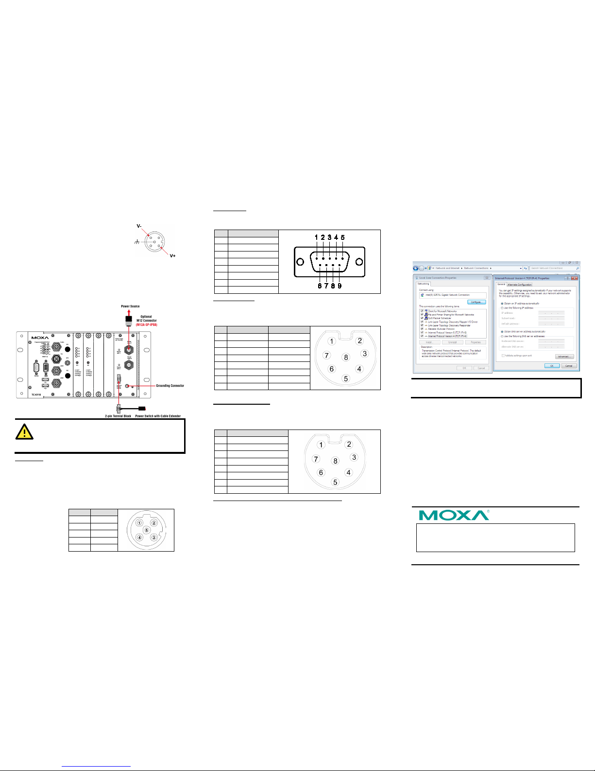
4. Configuring the Ethernet Interface
Follow these steps to configure the Ethernet interface for a static
network address (begins on next page).
Step 1: G o to Start=>Control Panel=>Network and
Internet=> Network Connections.
Step 2: Go to the Local Area Connection tab and click
Properties, then click Internet Protocol (TCP/IP), and
lastly select Proper ties.
Step 3: C lick OK after inputting the proper IP address and
netmask.
NOTE
Refer to the User’s Manual for additional configuration
information.
Pin
USB
1
D+ 2 D-
3
+5V
4
GND 5 N.C.
 Loading...