

Page 1

SMG-6100 Hardware
User’s Manual
First Edition, January 2011
www.moxa.com/product
© 2011 Moxa Inc. All rights reserved.
Reproduction without permission is prohibited.
Page 2

SMG-6100 Hardware
User’s Manual
The software described in this manual is furnished under a license agreement and may be used only in accordance with
the terms of that agreement.
Copyright Notice
Copyright ©2011 Moxa Inc.
All rights reserved.
Reproduction without permission is prohibited.
Trademarks
The MOXA logo is a registered trademark of Moxa Inc.
All other trademarks or registered marks in this manual belong to their respective manufacturers.
Disclaimer
Information in this document is subject to change without notice and does not represent a commitment on the part of
Moxa.
Moxa provides this document as is, without warranty of any kind, either expressed or implied, including, but not limited
to, its particular purpose. Moxa reserves the right to make improvements and/or changes to this manual, or to the
products and/or the programs described in this manual, at any time.
Infor mat ion prov ide d in thi s man ual is i nte n ded to b e ac cur a te a nd r eli able . Ho wev er, M oxa ass ume s no r esp ons ibil ity for
its use, or for any infringements on the rights of third parties that may result from its use.
This product might include unintentional technical or typographical errors. Changes are periodically made to the
information herein to correct such errors, and these changes are incorporated into new editions of the publication.
Technical Support Contact Information
www.moxa.com/support
Moxa Americas
Toll-free: 1-888-669-2872
Tel: +1-714-528-6777
Fax: +1-714-528-6778
Moxa Europe
Tel: +49-89-3 70 03 99-0
Fax: +49-89-3 70 03 99-99
Moxa China (Shanghai office)
Toll-free: 800-820-5036
Tel: +86-21-5258-9955
Fax: +86-21-5258-5505
Moxa Asia-Pacific
Tel: +886-2-8919-1230
Fax: +886-2-8919-1231
Page 3

Table of Contents
1. Introduction...................................................................................................................................... 1-1
Overview ...........................................................................................................................................1-2
Package Checklist ...............................................................................................................................1-2
Appearance........................................................................................................................................1-2
Dimensions ........................................................................................................................................ 1-3
Features ............................................................................................................................................ 1-3
Hardware Specifications ......................................................................................................................1-3
2. Hardware Installation ....................................................................................................................... 2-1
Placement Options ..............................................................................................................................2-2
Desktop .....................................................................................................................................2-2
Rack mounting ...................................................................................................................................2-2
Wiring Requirements...........................................................................................................................2-4
Connecting the Power .........................................................................................................................2-4
Reset Button ......................................................................................................................................2-5
Front Panel LED..................................................................................................................................2-5
Connecting to a Display ....................................................................................................................... 2-5
Connecting a PS/2 Keyboard and Mouse ................................................................................................2-6
Connecting USB Devices ...................................................................................................................... 2-7
LAN Ports ..........................................................................................................................................2-7
A. Safety Installation Instructions ........................................................................................................ A-1
B. Regulatory Statement Approval ........................................................................................................ B-1
Page 4

1
1. Introduction
Thank you for purchasing the Moxa SMG-6100 smart machine-to-machine (M2M) gateway.
This manual introduces the hardware installation, connector interfaces and BIOS setup of the SMG-6100. For
software configuration and management, please refer to the user’s manual for your operating system.
The following topics are covered in this chapter:
Overview
Package Checklist
Appearance
Dimensions
Features
Hardware Specifications
Page 5
SMG-6100 Hardware Introduction
Overview
The SMG-6100 is based on the Intel x86 processor and supports VGA, 4 Ethernet ports, 2 RS-232 serial ports,
and USB. It comes in a standard 19-inch, 1U high form factor with built-in IPSec, making it an ideal
communication platform for industrial machine-to-machine M2M applications.
The SMG-6100 can be used as a communication gateway with sophisticated M2M solutions to help construct a
tunnel server (IPSec) and bi-directional IP communications. When used with Moxa’s SMG-1100, the SMG-6100
can serve as a secure networking host over IPSec to back-end host computers and Modbus TCP Master/Slave
devices. One of the key benefits in this architecture is to facilitate and accelerate the remote monitoring and
management of Modbus devices.
Package Checklist
Before installing the SMG-6100, verify that the package contains the following items:
• 1 SMG-6100 gateway
• Ethernet cable: RJ45 to RJ45 cross-over cable, 100 cm
• Power cord
• Documentation and software CD
• Quick installation guide (printed)
• Warranty card
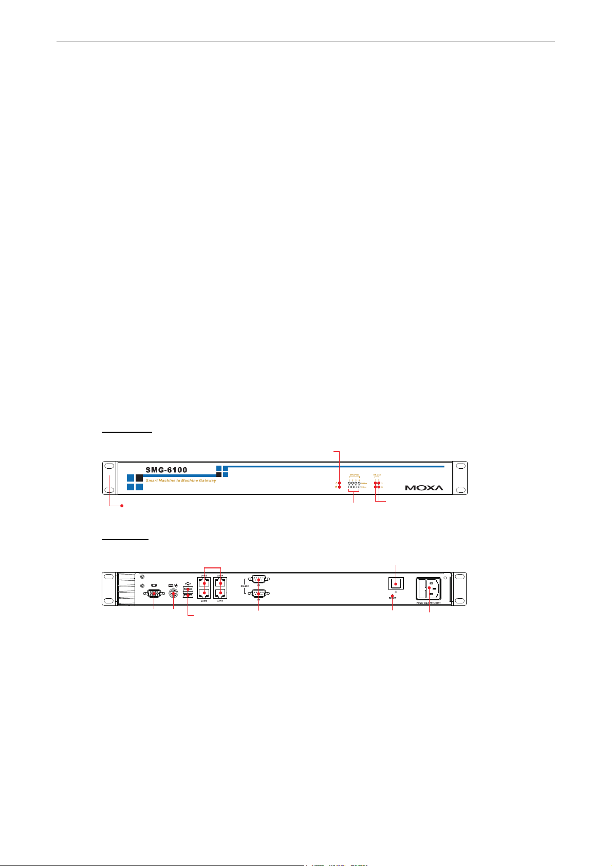
Appearance
Front View
19-inch
Rackmount Ear
Rear View
10/100 Mbps
Ethernet x 4
USB 2.0
Host x 2
RS-232
Serial Port x 2, DB9
LED Indicators
(Power, Storage)
LED Indicators
(10/100 Mbps)
LED Indicators (TX, RX)
Power Switch
Reset ButtonVGA PS/2
Power Input
1-2
Page 6

SMG-6100 Hardware Introduction
Dimensions
16,75
Features
• Secure communication platform with tunnel server (IPSec) for 2-way IP communication to distributed
SMG-1100s (Wireless Modbus Gateway).
• Networking host to back-end host computers and Modbus TCP Master/Slave devices.
• Supports unlimited Masters on serial or network side.
• Modbus and IPsec configuration tool.
303015
6.3
337
11.9
440
462
480
315
44
31.80
Hardware Specifications
SMG-6100
Ethernet Interface
LAN Auto-sensing 10/100 Mbps Ethernet x 4, using Realtek RTL8110SC Controller
Magnetic Isolation Protection 1.5 KV built-in
Serial Interface
Number of Ports RS-232 x 2 (reserved)
LEDs
System Power x 1, Storage x 1
LAN 10 Mbps x 4, 100 Mbps x 4
Serial RS-232 TX x 2, RX x 2
Physical Characteristics
Enclosure SECC sheet metal (1 mm)
Weight 4.5 kg
Dimensions 440 x 253 x 45 mm (17.32 x 9.96 x 1.77 in)
Mounting Standard 19-inch rackmount
1-3
Page 7

SMG-6100 Hardware Introduction
Switches and Buttons
Reset Button To reboot system hardware (on rear panel)
Environmental Limits
Operating Temperature -10 to 60°C (14 to 140°F)
Operating Humidity 5 to 95% RH
Storage Temperature -20 to 80°C (4 to 176°F)
Power Requirements
Input Voltage 100 to 240 VAC/VDC auto-ranging (47 to 63 Hz for AC input)
Power Consumption 50W
Input Rating 100-240VAC, 47-63Hz, 1.0A-0.5A
Regulatory Approvals
EMC FCC, CE (Class A), EMC level 4
Safety LVD, UL cUL, CCC
Reliability
Alert Tools Built-in buzzer and RTC (real-time clock) with battery lithium backup
Warranty
Warranty Period 3 years (details: see www.moxa.com/warranty)
1-4
Page 8

2
2. Hardware Installation
The SMG-6100 smart M2M gateway is compact and rugged, making it suitable for industrial
machine-to-machine applications. The LED indicators allow users to monitor performance and identify trouble
spots quickly, and multiple ports are provided for connecting a variety of different devices. The SMG-6100
machine-to-machine gateway comes with a reliable and stable hardware platform that lets you devote the bulk
of your time to application development. This chapter describes hardware installation and connector interfaces
of the SMG-6100 machine-to-machine gateway.
The following topics are covered in this chapter:
Placement Options
Desktop
Rack mounting
Wiring Requirements
Connecting the Power
Reset Button
Front Panel LED
Connecting to a Display
Connecting a PS/2 Keyboard and Mouse
Connecting USB Devices
LAN Ports
Page 9

SMG-6100 Hardware Hardware Installation
Placement Options
Desktop
Place your SMG-6100 on a clean, flat, well-ventilated desktop. For better ventilation, leave some space
between the SMG-6100 and other equipment. Do not place equipment or objects on top of the SMG-6100, as
this might damage the computer’s internal components.
Rack mounting
The SMG-6100 has rackmount supports for installing on a standard rack.
Four rackmount screws are required to attach the SMG-6100 to a standard rack.
Rackmount screws
Follow these steps to install the SMG-6100 on a rack.
Step 1: Installing the rackmount supports.
Take the rackmount supports out of the
requires 6 screws to attach to
the rack.
packages. There are two rackmount ears and 12 screws. Each ear
Rackmount screws
Step 2: Installing the rackmount ears to the SMG-6100.
Use 6 screws to attach one rackm
the other side of the SMG-6100.
ount ear to one side of the SMG-6100. Repeat this procedure for the ear on
2-2
Page 10

SMG-6100 Hardware Hardware Installation
Step 3: Installing the SMG-6100 to a rack.
Gently slide the SMG-6100 onto the rack, and then use screws provided by the rack supplier to fix the
rackmount support to the rail.
NOTE r
That four screws are requi
screws on the right side.
As a final check, make sure that the four screws are firmly attached to the rack.
ed to attach the SMG-6100 to the rack. Use two screws on the left side and two
2-3
Page 11

SMG-6100 Hardware Hardware Installation
Wiring Requirements
The following common safety precautions should be observed before installing any electronic device:
• Use separate paths to route wiring for power and devices. If power wiring and device wiring paths must
cross, make sure the wires are perpendicular at the intersection point.
• You can use the type of signal transmitted through a wire to determine which wires should be kept separate.
The rule of thumb is that wiring that shares similar electrical characteristics can be bundled together.
• Keep input wiring and output wiring separate.
• When necessary, it is strongly advised that you label wiring to all devices in the system.
ATTENTION
Do not run signal or communication wiring and power wiring in the same wire conduit. To avoid interference,
wires with different signal characteristics should be routed separately.
ATTENTION
Safety First!
Be sure to disconnect the power cord before installing and/or wiring your device.
Electrical Current Caution!
Calculate the maximum possible current in each power wire and common wire. Observe all electrical codes
dictating the maximum current allowable for each wire size.
If the current goes above the maximum ratings, the wiring could overheat, causing serious damage to your
equipment.
Temperature Caution!
Be careful when handling the unit. When the unit is plugged in, the internal components generate heat, and
consequently the outer casing may feel hot to the touch.
Connecting the Power
To power on the SMG-6100 connect the power line to the SMG-6100’s AC power connector (located on the right
side of the rear panel) using the power cord shipped with the product, and then turn on the power switch. If the
power is properly supplied, the Power LED will light up first, and then the Storage LED will start blinking. It
takes about 30 to 60 seconds for the operating system to boot up.
If you find the computer has not been powered on, press the Power Switch to start the system.
Power LED
Storage LED
Power Switch
Power Input
2-4
Page 12

SMG-6100 Hardware Hardware Installation
Reset Button
Pressing the Reset button initiates a hardware warm reboot. The button plays the same role as a desktop PC’s
reset button. After pressing the reset button, the system will reboot automatically. During normal use, you
should NOT use the Reset Button. You should only use this button if the software is not working properly. To
protect the integrity of data being transmitted or processed, you should always reset the system from the
operating system with the software reboot function.
Front Panel LED
There are 14 LED indicators on the front panel. Information about each LED is given in the following table.
LED Name Color LED Description
Green Power is on. Power
Off No power input or power error.
Orange/
Blinking
Off Storage unit is idle.
Green 100 Mbps of Ethernet Port is active. Ethernet Port 100
Mbps
Off No activity.
Orange 10 Mbps of Ethernet Port is active. Ethernet Port 10 Mbps
Off No activity.
Green Serial port is transmitting data. Serial Port TX 1-2
Off No operation.
Orange Serial port is receiving data. Serial Port RX 1-2
Off No operation.
Data is being written to or read from the storage unit. Storage
LED Indicators
(Power, Storage)
LED Indicators
(10/100 Mbps)
Reset Button
LED Indicators (TX, RX)
Connecting to a Display
Your SMG-6100 comes with a D-Sub 15-pin female connector to connect to the VGA monitor. Be sure to
remove the power before you connect or disconnect the monitor cable.
VGA
51
10
1115
6
Pin No.
1 RED
2 GREEN
3 BLUE
4 ---
5 GND
Signal Definition
2-5
Page 13

SMG-6100 Hardware Hardware Installation
6 CRT_DETECT#
7 GND
8 GND
9 +5V
10 GND
11 ---
12 DDC_DATA
13 HSYNC
14 VSYNC
15 ---
Connecting a PS/2 Keyboard and Mouse
Your S M G - 610 0 c o m es w i t h a P S/2 m i n i -DIN c o n n ect o r t o c onn e c t t o a PS / 2 k e ybo a r d a nd PS / 2 m o use b y u s i ng
a Y-type cable. This 6-pin mini-DIN connector has the pin assignments shown below.
PS/2
Pin No.
1 PS/2 Keyboard Data
2 PS/2 Mouse Data
3 GND
Use the Y-type cable to convert the mini-DIN connector into two 6-pin mini-DIN connectors to connect both a
PS/2 keyboard and PS/2 mouse at the same time. (The Y-type cable is not included in the accessory package.
It should be purchased separately. You may also use the USB ports to connect your USB-based keyboard and
mouse.)
4 VCC
5 PS/2 Keyboard Clock
6 PS/2 Mouse Clock
Signal Definition
ATTENTION
Please note that without the Y-type cable, the PS/2 connector on the SMG-6100 can only work with a PS/2
keyboard. A PS/2 mouse will not function when directly connected to the PS/2 connector on the SMG-6100.
2-6
Page 14

SMG-6100 Hardware Hardware Installation
Connecting USB Devices
The SMG-6100 has two USB 2.0 ports on the rear panel. All of the ports are UHCI, Rev 2.0 compliant and
support Plug & Play and hot swapping. These ports can be used to connect USB devices, such as a keyboard,
mouse, USB flash disk, and USB CD-ROM.
LAN Ports
The SMG-6100 has 4 10/100 Mbps LAN ports. When the cable is properly connected, the LEDs on the RJ45
connectors will glow to indicate a proper connection.
8
1
LED Color Description
USB 2.0 Host x 2
10/100 Mbps LAN x 4
1
8
Pin No. Signal Definition
1 TX+
2 TX-
3 RX+
4 ---
5 ---
6 RX-
7 ---
8 ---
Green 100 Mbps of Ethernet Port is active. Ethernet Port 100 Mbps
Off No activity.
Orange 10 Mbps of Ethernet Port is active. Ethernet Port 10 Mbps
Off No activity.
The default IP addresses and netmasks of the LAN ports are as follows:
Default IP Address Netmask
LAN 1 192.168.127.253 255.255.255.0
LAN 2 192.168.126.254 255.255.255.0
LAN 3 192.168.125.254 255.255.255.0
LAN 4 192.168.124.254 255.255.255.0
2-7
Page 15

A. Safety Installation Instructions
A. RTC Battery Warning
CAUTION: There is a risk of explosion if battery is replaced by an incorrect type. Dispose of used batteries
according to the instructions.
B. Rackmount Warning
The following or similar rackmount instructions are included with the installation instructions:
(1) Elevated Operating Ambient: If installed in a closed or multi-unit rack assembly, the operating ambient
temperature of the rack environment may be greater than the room ambient temperature. Therefore,
consideration should be given to installing the equipment in an environment compatible with the maximum
ambient temperature (Tma) specified by the manufacturer.
(2) Reduced Air Flow: Installation of the equipment in a rack should be such that the amount of air flow
required for safe operation of the equipment is not compromised.
A
(3) Mechanical Loading: Mounting of the equipment in the rack should be such that a hazardous condition is
not achieved due to uneven mechanical loading.
(4) Circuit Overloading: Consideration should be given to the connection of the equipment to the supply
circuit and the effect that overloading of the circuits might have on overcurrent protection and supply wiring.
Appropriate consideration of equipment nameplate ratings should be used when addressing this concern.
(5) Reliable Grounding: Reliable grounding of rack-mounted equipment should be maintained. Particular
attention should be given to supply connections other than direct connections to the branch circuit (e.g., by
using power strips).
Page 16

B
B. Regulatory Statement Approval
This device complies with part 15 of the FCC Rules. Operation is subject to the following
two conditions: (1) This device may not cause harmful interference, and (2) this device
must accept any interference received, including interference that may cause unde
operation.
sired
Class A
device, pursuant to part 15 of the FCC Rules. These limits are designed to provide reasonable protection
against harmful interference when the equipment is operated in a commercial environment. This equipment
generates, uses, and can radiate radio frequency energy and, if not installed and used in accordance with the
instruction manual, may cause harmful interference to radio communications. Operation of this equipment in
a residential area is likely to cause harmful interference in which case the user will be required to correct the
interference at his own expense.
Warning:
This is a Class A product. In a domestic environment this product may cause radio interference in which case
the user may be required to take adequate measures.
: FCC Warning! This equipment has been tested and found to compl y w ith th e l i mits for a Class A digital
European Community
 Loading...