

Page 1

P/N: 1802001901013
*1802001901013*
PWR-190-AC/DC,
PWR-2190-AC/DC
Quick Installation Guide
AC/DC Power Module
Edition 4.0, March 2017
Technical Support Contact Information
www.moxa.com/support
Moxa Americas:
Toll
-free: 1-888-669-2872
Tel:
1-714-528-6777
Fax:
1-714-528-6778
Moxa China (Shanghai office):
Toll
-free: 800-820-5036
Tel:
+86-21-5258-9955
Fax:
+86-21-5258-5505
Moxa Europe
:
Tel:
+49-89-3 70 03 99-0
Fax:
+49-89-3 70 03 99-99
Moxa Asia
-Pacific:
Tel:
+886-2-8919-1230
Fax:
+886-2-8919-1231
Moxa India:
Tel:
+91-80-4172-9088
Fax:
+91-80-4132-1045
2017 Moxa Inc. All rights reserved.
Page 2
- 2 -
Introduction
The PWR-190-AC/DC and PWR-2190-AC/DC power modules are designed
for the NRack Systems’ TRC-190/2190 chassis. They transform the AC
power input into a steady 12 VDC, or DC power input from 36 to 53 VDC
to a steady 12 VDC output to power the slide-in modules for the TRC-190.
Package Checklist
• PWR-190/2190-AC x 1 or PWR-190/2190-DC x 1
• Power cord
• Quick installation guide (printed)
• Warranty card
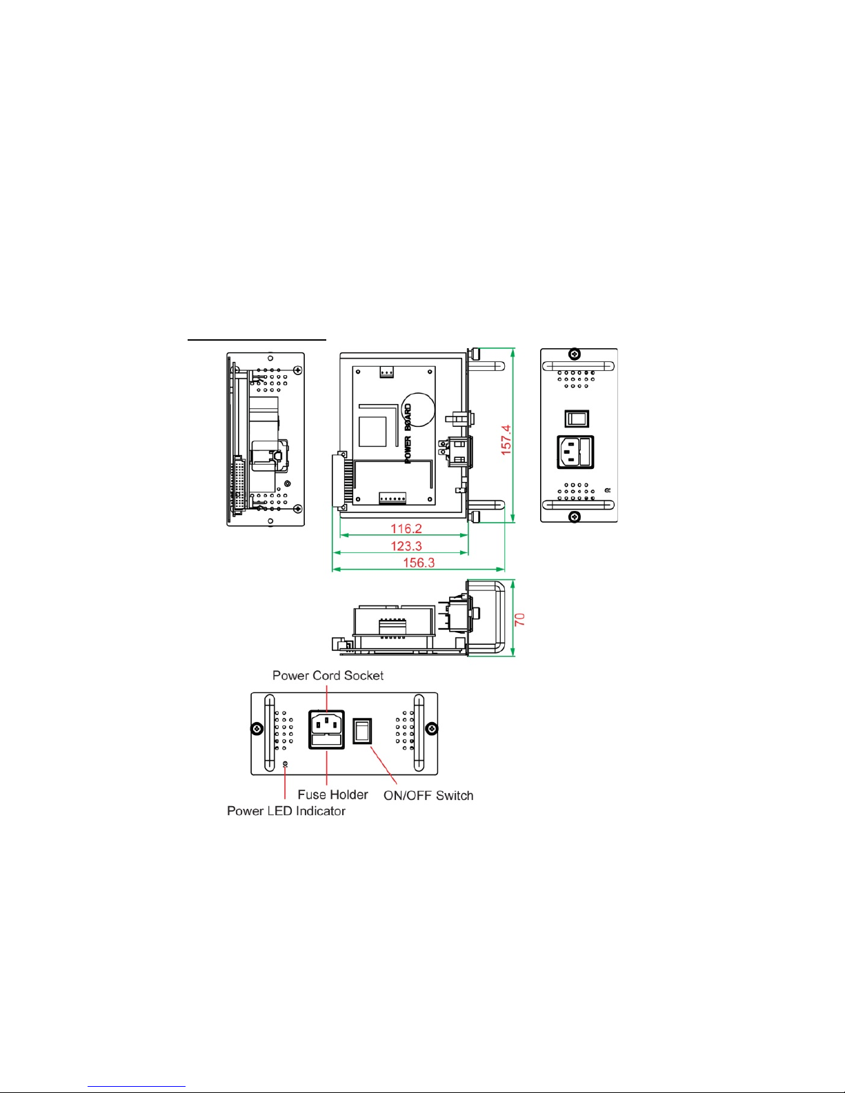
Dimensions (unit = mm)
PWR-190/2190-AC
Page 3
- 3 -
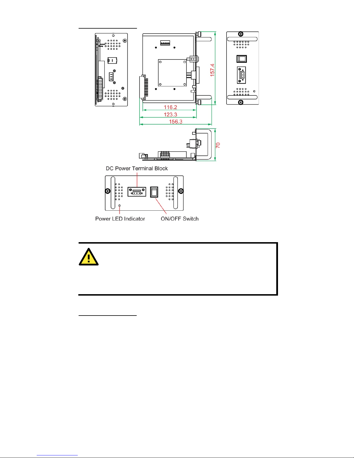
PWR-190/2190-DC
Powering the AC/DC Power Supply Module
ATTENTION
Ensure before connecting to the external power source, the
ON/OFF switch must be set
to “O
”. Failure to observe this caution
could result in damage to, and subsequent failure of, the power
supply module and human life.
Follow the instructions below to power on the power supply modules.
PWR-190/2190-AC
1. Set the ON/OFF switch to “O”.
2. Connect the female end of the power cord to the AC power connector
on the power supply module.
3. Plug the male end on the power cord into the correct voltage AC rack
or wall socket.
4. Set the ON/OFF switch to “l”.
5. Check whether the power LED is illuminated or not to see if the
power supply module is working.
Page 4

- 4 -
PWR-190/2190-DC
1. Set the ON/OFF switch to “O”.
2. Be sure that the external power source is NOT powered.
3. Connect the power cord and the shielding ground to the male
terminal block.
4. Link the male and female terminal blocks.
5. Tighten the screws (clockwise) to secure the male and female
terminals.
6. Power up the external power source.
7. Set the ON/OFF switch to “l”.
8. Check whether or not the power LED is illuminated to see if the
power supply module is working.
Power Supply Module Installation
ATTENTION
Do not connect the power supply module to the external power
source before install it into the chassis. Failure to observe this
may cause equipment damage, personal injury, or even death.
1. Install the AC power supply module and DC power supply module
the same way. The default power supply module will be in power
module Slot A. You can install an additional power supply module in
Slot B. Install or remove the power supply module from Slot A or
Slot B in the same manner.
2. Whether installing a power supply module in Slot A or Slot B, be sure
to remove the plate from the slot first. To remove the plate, remove
the 2 screws that secure the plate to the chassis.
Page 5
- 5 -
3. After removing the plate from the chassis, slowly slide the power
supply module into the chassis. Push the power supply module into
the chassis to ensure that it is all the way inside and firmly
connected to the chassis.
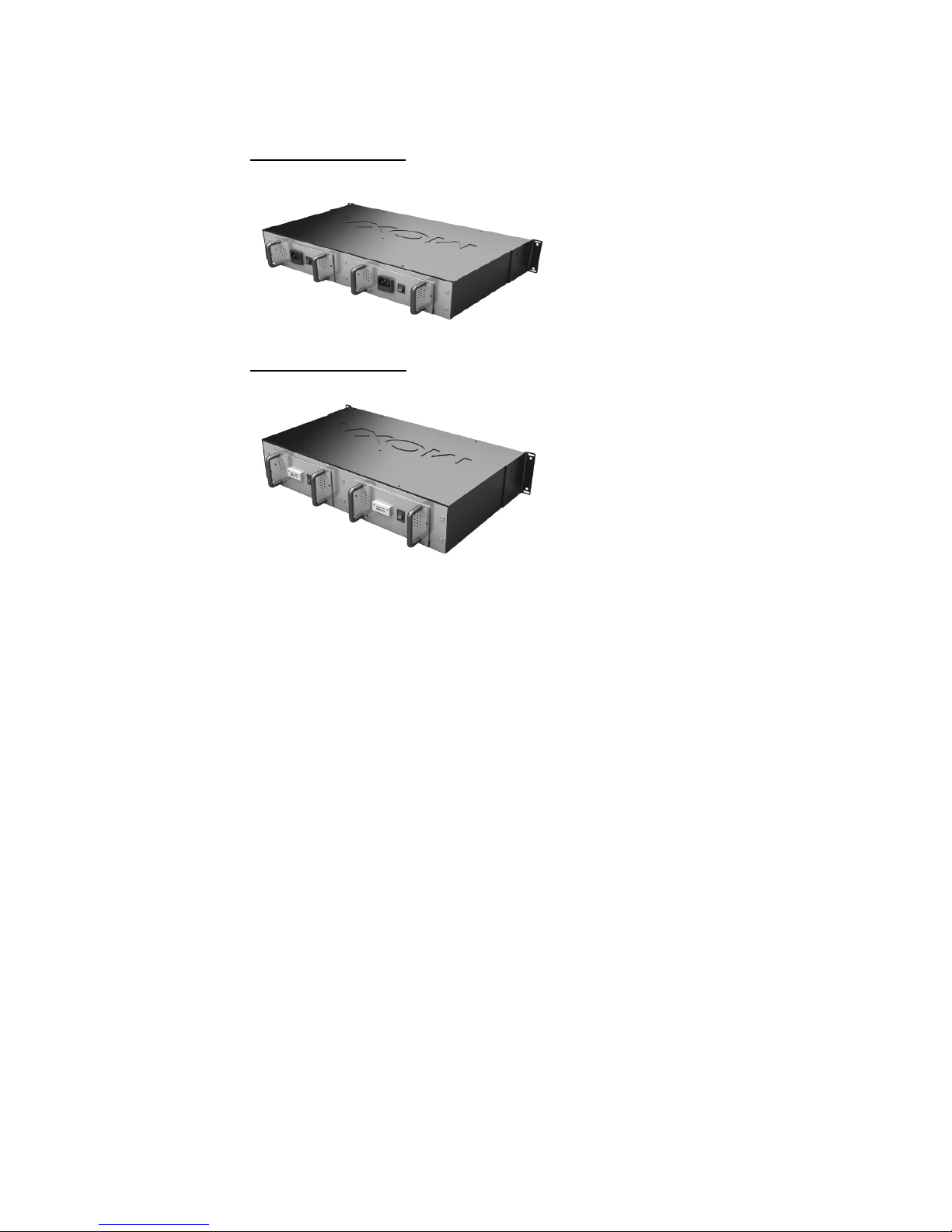
PWR-190/2190-AC
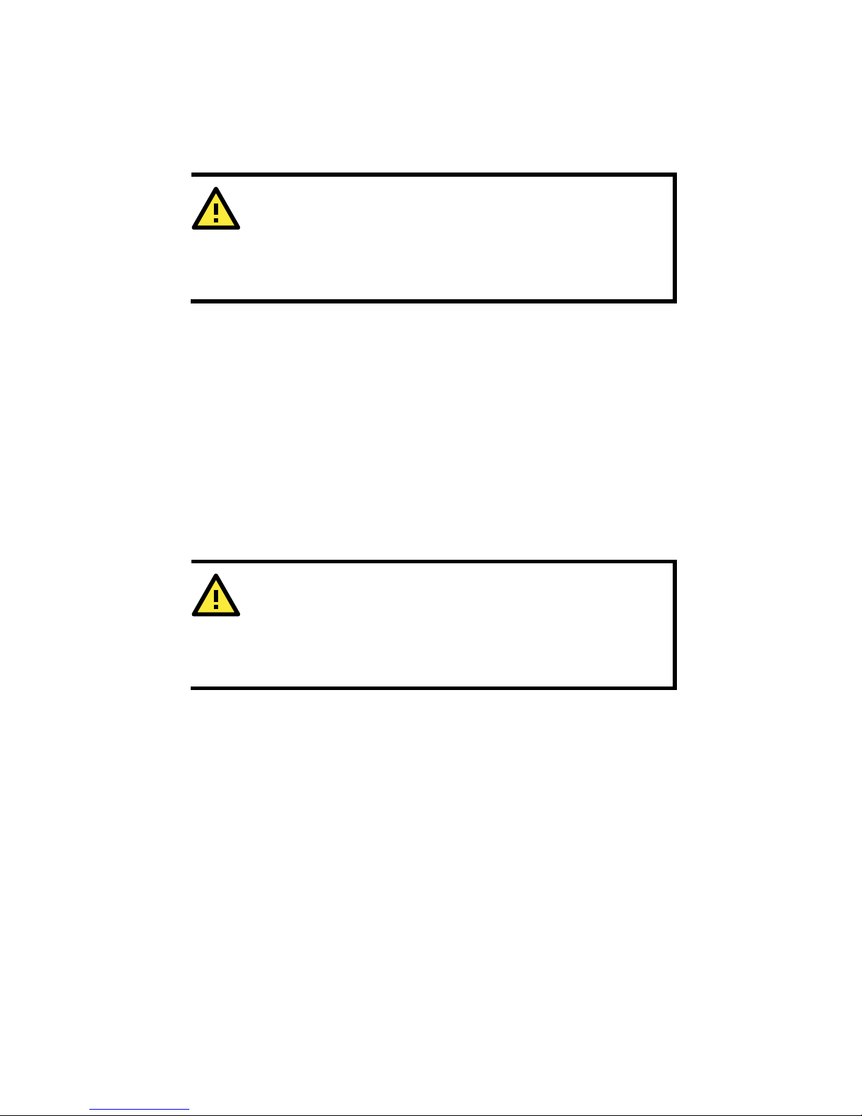
PWR-190/2190-DC
4. Screw the power supply module clockwise to secure the power
supply module in place.
5. Connect the power supply module to the external power source.
Power Supply Module Replacement
Replace the AC power supply module and DC power supply module the
same way. Do not remove the power supply module from the chassis
when the power source is connected and the external power switch is set
to “O”. When the chassis is equipped with 2 power supply modules, any
one of them can be hot swapped without stopping the other one.
1. Set the power supply module power switch to “O”.
2. Disconnect the power supply module from the external power
source.
3. Loosen the two screws on the power supply module.
4. Smoothly slide out the power supply module.
5. Install another new power supply module following the instructions
in the previous section.
Page 6
- 6 -
Replacing the Power Supply
Fuses(PWR-190/2190-AC module only)
You do not need to remove the power supply module from the chassis in
order to replace the fuse in the module.
ATTENTION
Wear a
grounding device and observe electrostatic discharge
precautions when replacing the fuse in the power supply module.
Failure to observe this caution could result in damage to, and
subsequent failure of, the power supply module.
Follow the instructions below to change the fuse if needed.
1. Set the power switch on the power supply module to “O”.
2. Disconnect the power supply module from the external power
source.
3. From the inside edge of the power connector, insert a flat blade
screwdriver into the groove at the front. Gently pry the fuse holder
out of the power connector.
4. Remove the fuse from the holder carefully.
5. The replacement fuse must be the same size and rating as the
original. Installing a fuse of a different size or rating may damage
your power module or even the entire system.
6. Plug the fuse holder back into its original location.
7. Connect the power supply module to the external power source.
ATTENTION
Do not connect the power supply module to the external power
source
before installing it in the chassis. Failure to observe this
may cause the equipment damage, personal injury, or even
death.
Page 7

- 7 -
Specifications
Physical Characteristics
Case
SECC (1.2 mm)
Dimensions
157.4 x 123.3 x 70 mm (18.6 x 11 x 3.3 in.)
Gross Weight
0.5 kg or 1.1 lbs
Environment
Operating Temperature
0 to 60°C (32 to 140°F)
Operating Humidity
5% to 95% RH
Storage Temperature
-40 to 85°C (-40 to 185°F)
Power Requirement
Input Voltage
Universal 100 to 240 VAC 47-63 Hz or 48 VDC
Max. Power Output
5.4 A @ 12 VDC
Regulatory Approvals
CE
Class B
FCC
Part 15 Subpart B Class A
EMI
EN55022 1998, Class B
EMS
EN61000-4-2 (ESD), Criteria A, Level 4
EN61000
-4-3 (RS), Criteria A, Level 2
EN61000
-4-4 (EFT), Criteria A, Level 3
EN61000
-4-5 (Surge), Criteria A, Level 3
EN61000
-4-6 (CS), Criteria A, Level 2
EN61000-4-8 (PFMF), Criteria A, Level 3
 Loading...