

Page 1

PT-G7828/G7728 User’s Manual
Edition 1.0, December 2017
www.moxa.com/product
© 2017 Moxa Inc. All rights reserved.
www.ipc2u.ru
www.moxa.pro
Page 2

PT-G7828/G7728 User’s Manual
The software described in this manual is furnished under a license agreement and may be used only in accordance with
the terms of that agreement.
Copyright Notice
© 2017 Moxa Inc. All rights reserved.
Trademarks
The MOXA logo is a registered trademark of Moxa Inc.
All other trademarks or registered marks in this manual belong to their respective manufacturers.
Disclaimer
Information in this document is subject to change without notice and does not represent a commitment on the part of
Moxa.
Moxa provides this document as is, without warranty of any kind, either expressed or implied, including, but not limited
to, its particular purpose. Moxa reserves the right to make improvements and/or changes to this manual, or to the
products and/or the programs described in this manual, at any time.
Information provided in this manual is intended to be accurate and reliable. However, Moxa assumes no responsibility for
its use, or for any infringements on the rights of third parties that may result from its use.
This product might include unintentional technical or typographical errors. Changes are periodically made to the
information herein to correct such errors, and these changes are incorporated into new editions of the publication.
Technical Support Contact Information
www.moxa.com/support
Moxa Americas
Toll
-free: 1-888-669-2872
Tel:
+1-714-528-6777
Fax:
+1-714-528-6778
Moxa China (Shanghai office)
Toll
-free: 800-820-5036
Tel:
+86-21-5258-9955
Fax:
+86-21-5258-5505
Moxa Europe
Tel:
+49-89-3 70 03 99-0
Fax:
+49-89-3 70 03 99-99
Moxa Asia
-Pacific
Tel:
+886-2-8919-1230
Fax:
+886-2-8919-1231
Moxa India
Tel:
+91-80-4172-9088
Fax:
+91-80-4132-1045
www.ipc2u.ru
www.moxa.pro
Page 3

Table of Contents
1. About this Manual ............................................................................................................................. 1-1
2. Getting Started.................................................................................................................................. 2-1
USB Console Configuration (115200, None, 8, 1, VT100) ......................................................................... 2-2
Configuration by Command Line Interface (CLI) ..................................................................................... 2-4
Configuration by Web Console .............................................................................................................. 2-6
Disabling Telnet and Browser Access ..................................................................................................... 2-7
3. Featured Functions ........................................................................................................................... 3-1
Home ................................................................................................................................................ 3-2
System Settings ................................................................................................................................. 3-2
System Information ..................................................................................................................... 3-2
Module Information ..................................................................................................................... 3-3
User Account .............................................................................................................................. 3-4
Password Login Policy .................................................................................................................. 3-6
Network ..................................................................................................................................... 3-6
Date and Time ............................................................................................................................ 3-9
IEEE 1588 ................................................................................................................................ 3-10
Warning Notification .................................................................................................................. 3-17
MAC Address Table .................................................................................................................... 3-24
System Files ............................................................................................................................. 3-25
Restart ..................................................................................................................................... 3-28
Factory Default ......................................................................................................................... 3-28
PoE (PoE Models Only) ...................................................................................................................... 3-29
PoE Settings ............................................................................................................................. 3-29
VLAN ............................................................................................................................................... 3-39
The Virtual LAN (VLAN) Concept .................................................................................................. 3-39
Sample Applications of VLANs Using Moxa Switches ....................................................................... 3-41
Configuring a Virtual LAN ........................................................................................................... 3-42
VLAN Name Setting ................................................................................................................... 3-44
QinQ Settings ........................................................................................................................... 3-44
VLAN Table ............................................................................................................................... 3-44
Port ................................................................................................................................................ 3-45
Port Settings ............................................................................................................................. 3-45
Port Status ............................................................................................................................... 3-46
Link Aggregation ....................................................................................................................... 3-47
Link-Swap Fast Recovery ........................................................................................................... 3-49
RSTP Grouping ................................................................................................................................. 3-49
Multicast .......................................................................................................................................... 3-50
The Concept of Multicast Filtering ................................................................................................ 3-50
IGMP Snooping ......................................................................................................................... 3-53
IGMP Snooping Setting .............................................................................................................. 3-54
IGMP Group Status .................................................................................................................... 3-55
Stream Table ............................................................................................................................ 3-55
Static Multicast Address ............................................................................................................. 3-56
GMRP ....................................................................................................................................... 3-57
Multicast Filtering Behavior ......................................................................................................... 3-57
QoS ................................................................................................................................................ 3-58
The Traffic Prioritization Concept ................................................................................................. 3-58
Configuring Traffic Prioritization .................................................................................................. 3-60
CoS Classification ...................................................................................................................... 3-60
Priority Mapping ........................................................................................................................ 3-61
DSCP Mapping .......................................................................................................................... 3-62
Rate Limiting ............................................................................................................................ 3-62
Security ........................................................................................................................................... 3-64
Management Interface ............................................................................................................... 3-64
Trusted Access .......................................................................................................................... 3-66
SSL Certificate Management ....................................................................................................... 3-67
SSH Key Management ................................................................................................................ 3-67
Authentication .......................................................................................................................... 3-67
Port Security ............................................................................................................................. 3-74
Port Access Control Table ........................................................................................................... 3-77
Loop Protection ......................................................................................................................... 3-77
Access Control List .................................................................................................................... 3-77
DHCP .............................................................................................................................................. 3-84
IP-Port Binding.......................................................................................................................... 3-84
DHCP Relay Agent ..................................................................................................................... 3-84
SNMP .............................................................................................................................................. 3-87
SNMP Read/Write Settings .......................................................................................................... 3-88
Trap Settings ............................................................................................................................ 3-89
www.ipc2u.ru
www.moxa.pro
Page 4

Industrial Protocols ........................................................................................................................... 3-93
Diagnostics ...................................................................................................................................... 3-93
LLDP ........................................................................................................................................ 3-93
Ping ......................................................................................................................................... 3-94
Port Mirroring ........................................................................................................................... 3-94
Monitoring ....................................................................................................................................... 3-95
CPU/Memory Utilization .............................................................................................................. 3-95
Statistics .................................................................................................................................. 3-96
Fiber Digital Diagnostics Monitoring (Fiber Check) ......................................................................... 3-97
Event Log ................................................................................................................................. 3-99
Tracking Function ...................................................................................................................... 3-99
Substation ..................................................................................................................................... 3-105
IEC 61850 QoS ....................................................................................................................... 3-105
GOOSE Check ......................................................................................................................... 3-105
MMS server ............................................................................................................................ 3-107
A. MIB Groups ....................................................................................................................................... A-1
www.ipc2u.ru
www.moxa.pro
Page 5

1
1. About this Manual
Thank you for purchasing a Moxa managed Ethernet switch. Read this user’s manual to learn how to connect
your Moxa switch to Ethernet-enabled devices used for industrial applications.
A synopsis of chapters 2 and 3 are given below:
Chapter 2: Getting Started
In this chapter, we explain the initial installation process for a Moxa switch. Moxa switches provide three
interfaces to access the configuration settings: USB console interface, command line interface, and web
console interface.
Chapter 3: Featured Functions
In this chapter, we explain how to access a Moxa switch’s various configuration, monitoring, and
management functions. The functions can be accessed by USB console, Telnet console, and web console
(web browser). We describe how to configure the switch functions via web console, which provides the most
user-friendly way to configure a Moxa switch.
www.ipc2u.ru
www.moxa.pro
Page 6

2
2. Getting Started
In this chapter, we explain how to install a Moxa switch for the first time. There are three ways to access the
Moxa switch’s configuration settings: USB console, command line interface, or web-based interface. If you do
not know the Moxa switch’s IP address, you can open the USB console by connecting the Moxa switch to a PC’s
USB port with a USB cable. You can open the Telnet or web-based console over an Ethernet LAN or over the
Internet.
The following topics are covered in this chapter:
USB Console Configuration (115200, None, 8, 1, VT100)
Configuration by Command Line Interface (CLI)
Configuration by Web Console
Disabling Telnet and Browser Access
www.ipc2u.ru
www.moxa.pro
Page 7
PT-G7828/G7728 Getting Started
2-2
USB Console Configuration (115200, None, 8, 1,
VT100)
NOTE
A
Moxa switch allows multi-session connections (up to 6) by connecting to the web console and another
console (serial or Telnet) at the same time.
NOTE
We recommend
using PComm Terminal Emulator when opening the USB console. This software can be
downloaded free of charge from the Moxa website.
Before running PComm Terminal Emulator, first install the USB console driver on your PC and then connect the
Moxa switch’s USB console port to your PC’s USB port with a USB cable.
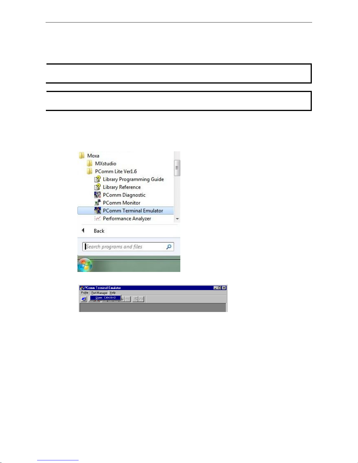
After installing PComm Terminal Emulator, open the Moxa switch’s USB console as follows:
1. From the Windows desktop, click Start Moxa PComm Lite Ver1.6 Terminal Emulator.
2. Select Open under the Port Manager menu to open a new connection.
www.ipc2u.ru
www.moxa.pro
Page 8
PT-G7828/G7728 Getting Started
2-3
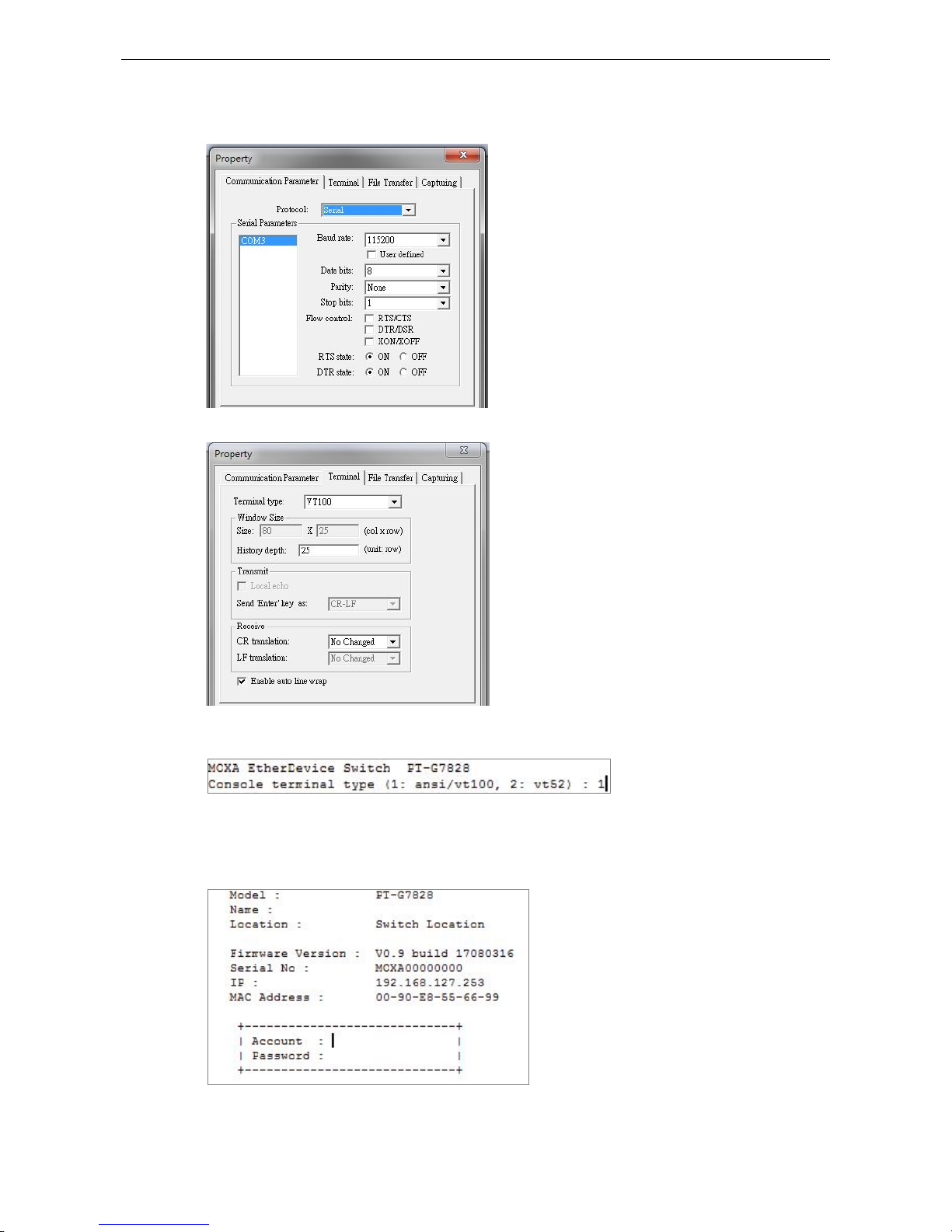
3. The Property window should open. On the Communication Parameter tab for Ports, select the COM
port that is being used for the console connection. Set the other fields as follows: 115200 for Baud Rate,
8 for Data Bits, None for Parity, and 1 for Stop Bits.
4. On the Terminal tab, select VT100 for Terminal Type, and then click OK to continue.
5. In the terminal window, the Moxa switch will prompt you to select a terminal type. Enter 1 to select
ansi/vt100 and then press Enter.
6. The USB console will prompt you to log in. Press Enter and select admin or user. Use the down arrow key
on your keyboard to select the Password field and enter a password if desired. This password will be
required to access any of the consoles (web, serial, Telnet).
www.ipc2u.ru
www.moxa.pro
Page 9
PT-G7828/G7728 Getting Started
2-4
NOTE
By default, the
password assigned to the Moxa switch is moxa. Be sure to
change the default password after
you first
log in to help keep your system secure.
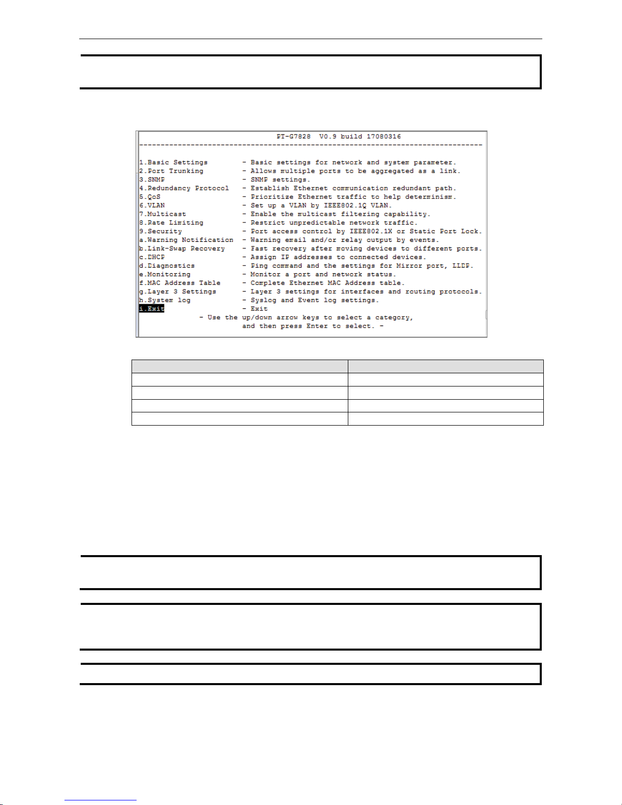
7. The Main Menu of the Moxa switch’s USB console should appear. (In PComm Terminal Emulator, you can
adjust the font by selecting Font… from the Edit menu.)
8. Use the following keys on your keyboard to navigate the Moxa switch’s USB console:
Key Function
Up, down, right, left arrow keys, Tab
Move the onscreen cursor
Enter Display and select options
Space Toggle options
Esc Previous menu
Configuration by Command Line Interface (CLI)
Opening the Moxa switch’s Telnet or web console over a network requires that the PC host and Moxa switch are
on the same logical subnet. You may need to adjust your PC host’s IP address and subnet mask. By default, the
Moxa switch’s IP address is 192.168.127.253 and the Moxa switch’s subnet mask is 255.255.255.0 (referred to
as a Class B network). Your PC’s IP address must be set to 192.168.xxx.xxx if the subnet mask is 255.255.0.0,
or to 192.168.127.xxx if the subnet mask is 255.255.255.0.
NOTE
To connect to the Moxa switch’s Telnet or web console, your PC host and the Moxa switch must be on the same
logical subnet.
NOTE
When connecting to the Moxa switch’s Telnet or web console, first connect one of the Moxa switch’s Ethernet
ports to your Ethernet LAN,
or directly to your PC’s Ethernet port. You may use either a straight-
through or
cross
-over Ethernet cable.
NOTE
The Moxa switch’s default IP address is 192.168.127.253.
After making sure that the Moxa switch is connected to the same LAN and logical subnet as your PC, open the
Moxa switch’s Telnet console as follows:
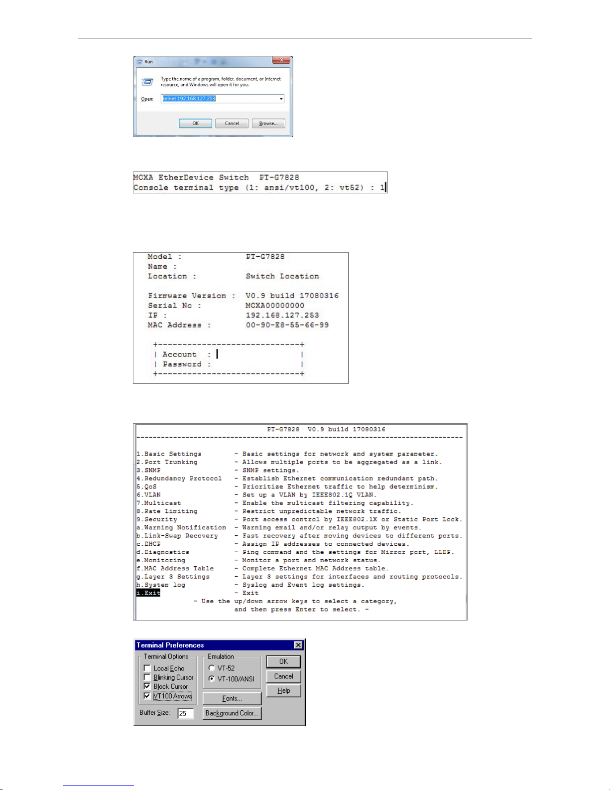
1. Click Start Run from the Windows Start menu and then Telnet to the Moxa switch’s IP address from the
Windows Run window. You may also issue the Telnet command from a DOS prompt.
www.ipc2u.ru
www.moxa.pro
Page 10
PT-G7828/G7728 Getting Started
2-5
2. In the terminal window, the Telnet console will prompt you to select a terminal type. Type 1 to choose
ansi/vt100, and then press Enter.
3. The Telnet console will prompt you to log in. Press Enter and then select admin or user. Use the down
arrow key on your keyboard to select the Password field and enter a password if desired. This password
will be required to access any of the consoles (web, serial, Telnet). If you do not wish to create a password,
leave the Password field blank and press Enter.
4. The Main Menu of the Moxa switch’s Telnet console should appear.
www.ipc2u.ru
www.moxa.pro
Page 11
PT-G7828/G7728 Getting Started
2-6
5. Use the following keys on your keyboard to navigate the Moxa switch’s Telnet console:
Key Function
Up, down, right, left arrow keys, Tab Move the onscreen cursor
Enter Display and select options
Space Toggle options
Esc Previous menu
NOTE
The Telnet console looks and operates in precisely the same manner as the
USB console.
Configuration by Web Console
The Moxa switch’s web console is a convenient platform for modifying the configuration and accessing the
built-in monitoring and network management functions. You can open the Moxa switch’s web console using a
standard web browser, such as Internet Explorer.
NOTE
When connecting to the Moxa switch’s Telnet or web console, your PC host and the Moxa switch must be on
the same logical subnet.
NOTE
If the Moxa switch is configured for other VLAN settings, you must make sure your PC host is on the
management
VLAN.
NOTE
When connecting to the Moxa switch’s Telnet or web console, first connect one of the Moxa switch’s Ethernet
ports to your Ethernet LAN, or directly to your PC’s Ethernet port. You may use either a straight-through or
cross
-over Ethernet cable.
NOTE
The Moxa switch’s default IP address is 192.168.127.253.
After making sure that the Moxa switch is connected to the same LAN and logical subnet as your PC, open the
Moxa switch’s web console as follows:
1. Connect your web browser to the Moxa switch’s IP address by entering it in the Address or URL field.
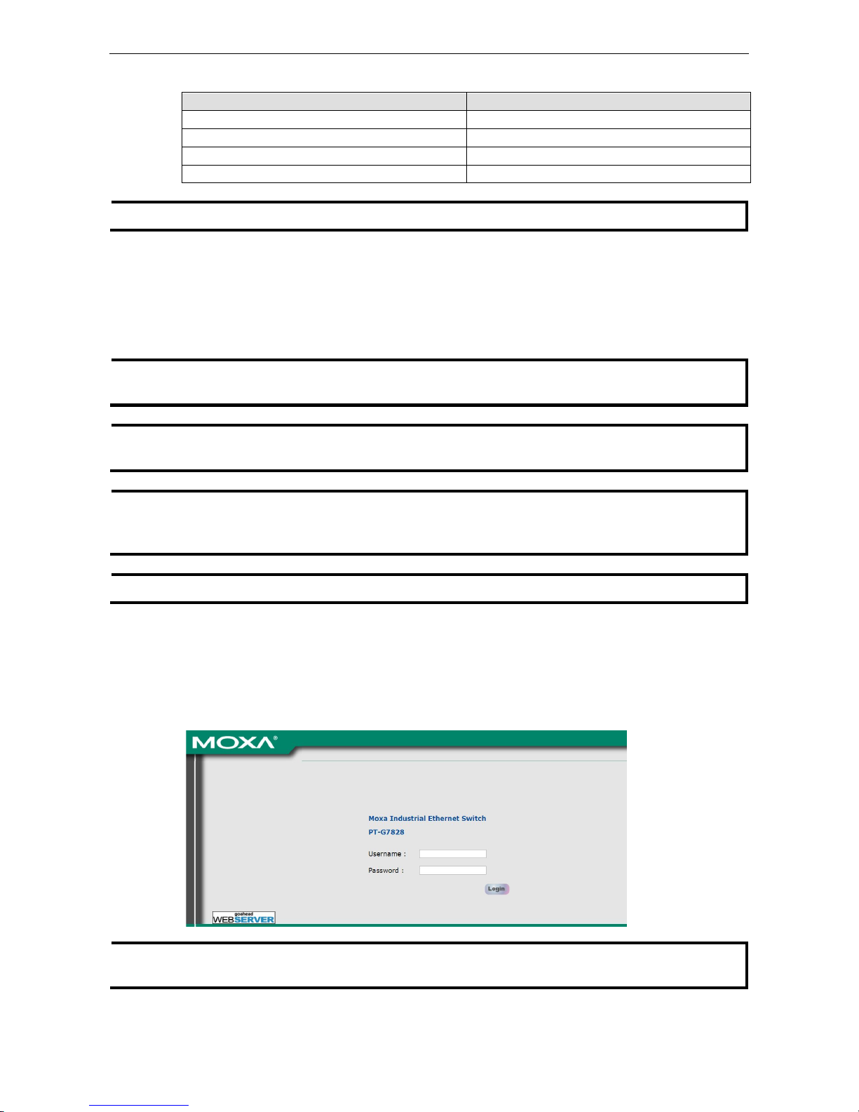
2. The Moxa switch’s web console will open, and you will be prompted to log in. Select the login account
(admin or user) and enter the Password. This password will be required to access any of the consoles (web,
serial, Telnet). If you do not wish to create a password, leave the Password field blank and press Enter.
NOTE
By default, the
password assigned to the Moxa switch is moxa. Be sure to
change the default password after
you first
log in to help keep your system secure.
www.ipc2u.ru
www.moxa.pro
Page 12
PT-G7828/G7728 Getting Started
2-7
3. After logging in, you may need to wait a few moments for the web console to appear. Use the folders in the
left navigation panel to navigate between different pages of configuration options.
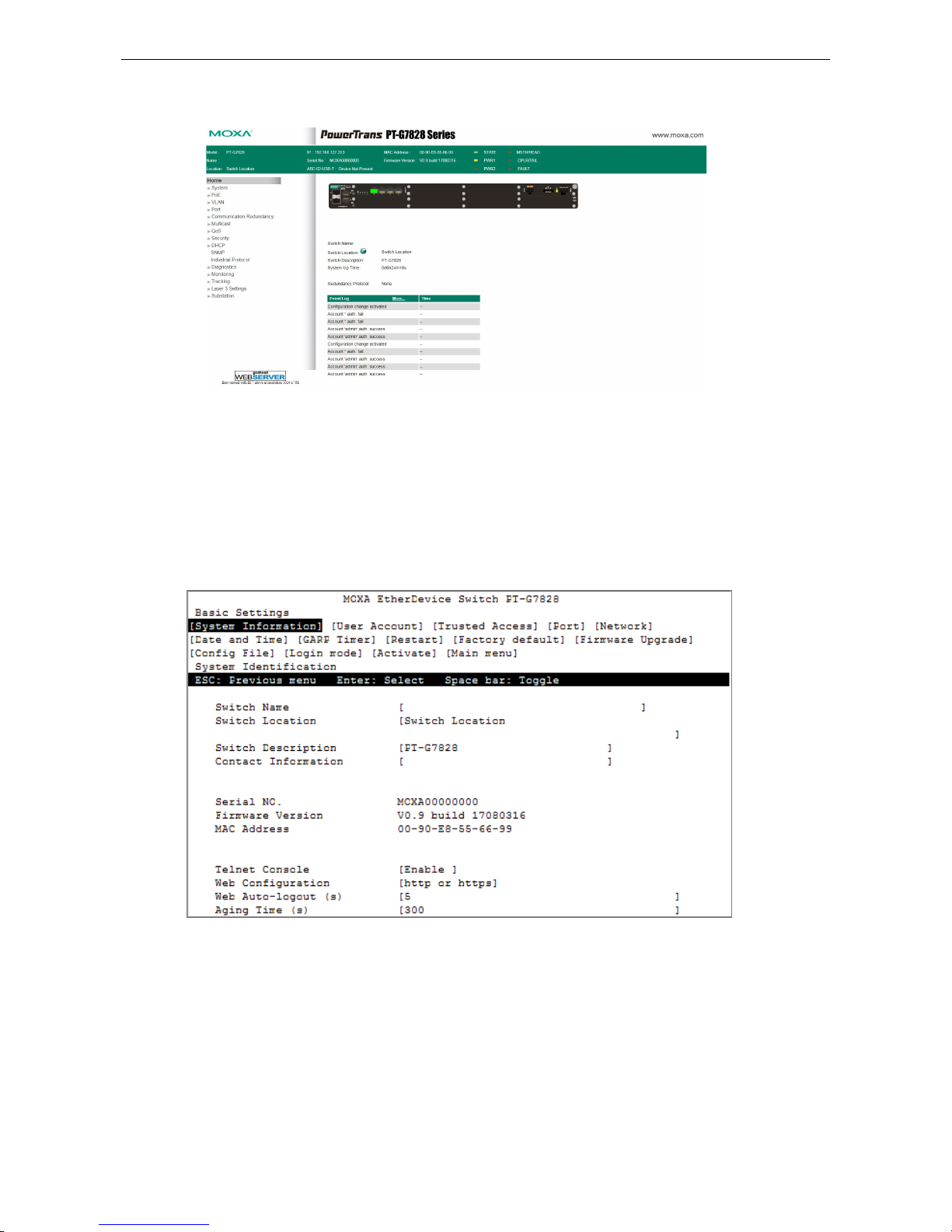
Disabling Telnet and Browser Access
If you are connecting the Moxa switch to a public network but do not intend to manage it over the network, we
suggest disabling both the Telnet and web consoles. This is done from the USB console by navigating to
System Identification under Basic Settings
System Information. Disable or enable the Telnet
Console and Web Configuration as shown below:
www.ipc2u.ru
www.moxa.pro
Page 13

3
3. Featured Functions
In this chapter, we explain how to access the Moxa switch’s various configuration, monitoring, and
management functions. These functions can be accessed by USB console, Telnet console, or web console. The
USB console can be used if you do not know the Moxa switch’s IP address. To access the USB console, connect
switch’s USB port to your PC’s COM port. The Telnet and web consoles can be opened over an Ethernet LAN or
the Internet.
The web console is the most user-friendly interface for configuring a Moxa switch. In this chapter, we use the
web console interface to introduce the console functions. There are only a few differences between the web
console, USB console, and Telnet console.
The following topics are covered in this chapter:
Home
System Settings
System Information
User Account
Password Login Policy
Network
Date and Time
www.ipc2u.ru
www.moxa.pro
Page 14
PT-G7828/G7728 Featured Functions
3-2
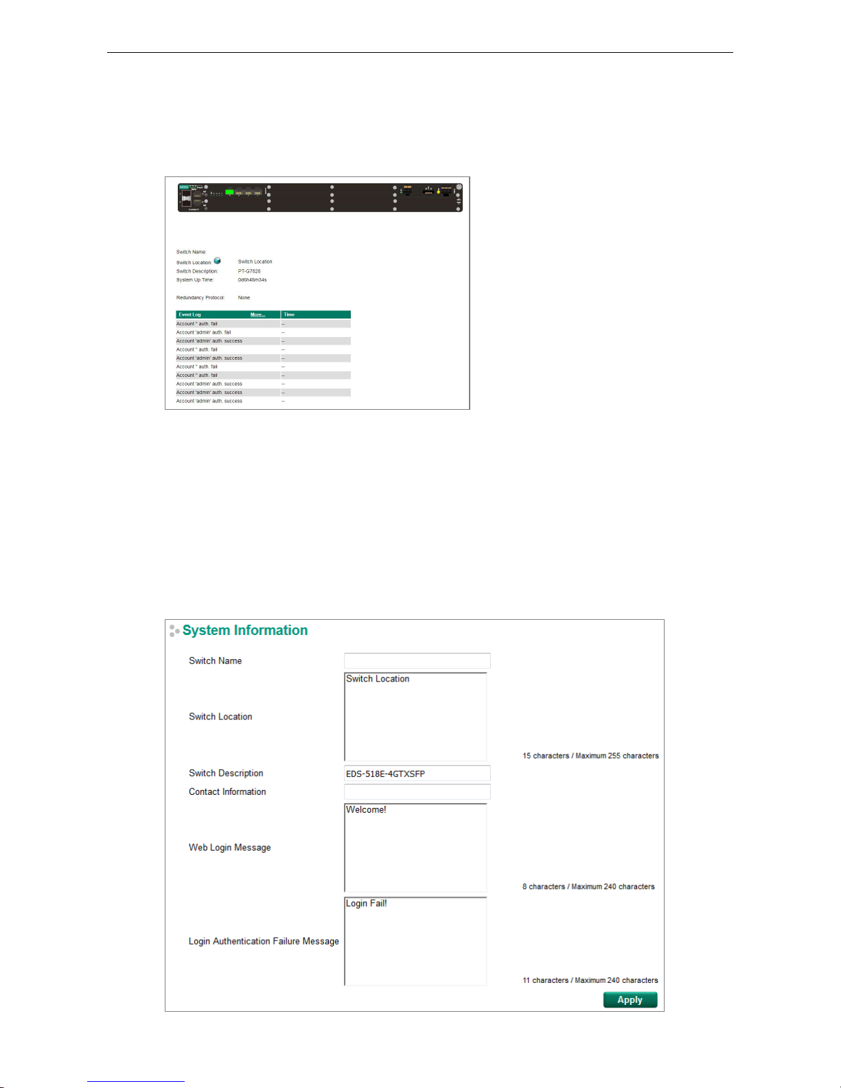
Home
The Home page shows the summary of the Moxa switch information including System Information,
Redundancy Protocol, Event Log, and Device virtualization panel. By showing the switch's information and
event log, the operators can easily understand the system and port link status at a glance.
System Settings
The System Settings section includes the most common settings required by administrators to maintain and
control a Moxa switch.
System Information
Define System Information items to make it easier to identify different switches that are connected to your
network.
www.ipc2u.ru
www.moxa.pro
Page 15
PT-G7828/G7728 Featured Functions
3-3
Switch Name
Setting Description Factory Default
Max. 30 characters This option is useful for differentiating between the roles or
applications of different units. Example: Factory Switch 1.
none
NOTE
The Switch Name field follows
the PROFINET I/O naming rule. The name can only include any of these
character
s, a-z/A-Z/0-9/-/., and the name cannot start with port-xyz or port-xyz-abcde where
xyzabcde=0...9 or is in the form n.n.n.n where n=0...9
Switch Location
Setting Description Factory Default
Max. 255 characters
This option is useful for differentiating between the locations of
different switches. Example: production line 1.
Switch Location
Switch Description
Setting Description Factory Default
Max. 30 characters This option
is useful for recording a more detailed description of
the unit.
Switch Model name
Contact Information
Setting Description Factory Default
Max. 30 characters This option is useful for providing information about who is
responsible for maintaining this unit and how to contact this
person.
None
Web Login Message
Setting Description Factory Default
Max. 240 characters This option is useful as it shows a message when a user’s
login
is successful
Switch Location
Login Authentication Failure Message
Setting Description Factory Default
Max. 240 characters This option is useful
as it shows a message when a user’s login
has failed
Switch Location
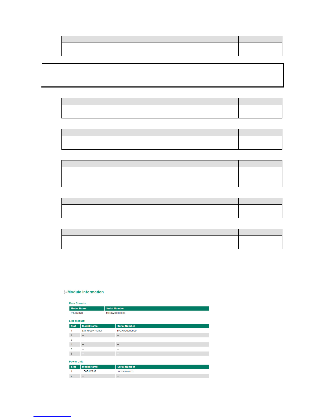
Module Information
This page displays the model name and serial number information of the device, including main chassis, line
module, and power module. Below is an example of the information that will be displayed.
www.ipc2u.ru
www.moxa.pro
Page 16
PT-G7828/G7728 Featured Functions
3-4
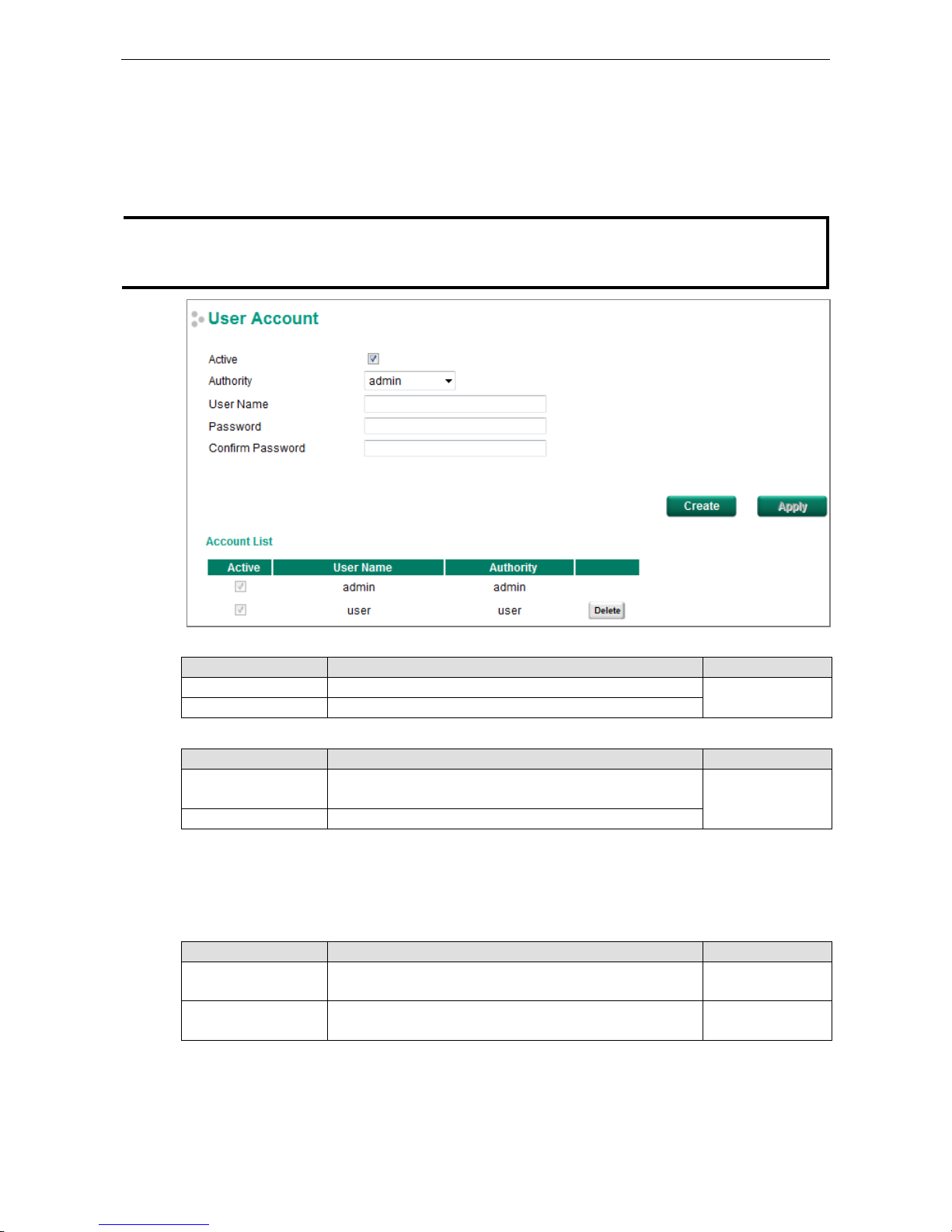
User Account
The Moxa switch supports the management of accounts, including establishing, activating, modifying, disabling,
and removing accounts. There are two levels of configuration access: admin and user. Accounts with admin
authority have read/write access of all configuration parameters, whereas accounts with user authority only
have read access to view configuration items.
NOTE
1.
In order to maintain a higher level of security, we strongly suggest that you change the password after
you
first log in.
2.
By default, the admin user account cannot be deleted or disabled.
Active
Setting Description Factory Default
Checked This account can access the switch’s configuration settings. Checked
Unchecked This account cannot access the switch’s configuration settings.
Authority
Setting Description Factory Default
admin This account has read/write access of all configuration
parameters.
admin
user This account can only view configuration parameters.
Creating a New Account
Click Create, type in the user name and password, and assign an authority to the new account. Click Apply to
add the account to the Account List table.
Setting Description Factory Default
User Name
(Max. of 30 characters)
User Name None
Password Password for the user account.
(between 4 and 16 characters)
None
www.ipc2u.ru
www.moxa.pro
Page 17
PT-G7828/G7728 Featured Functions
3-5
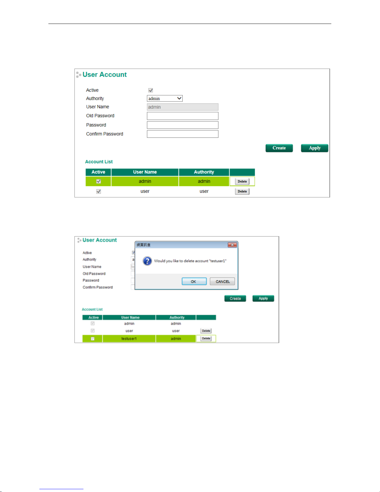
Modifying an Existing Account
Select an existing account from the Account List table, modify the account details, and then click Apply to save
the changes.
Deleting an Existing Account
Select an account from the Account List table and then click Delete to delete the account.
www.ipc2u.ru
www.moxa.pro
Page 18
PT-G7828/G7728 Featured Functions
3-6
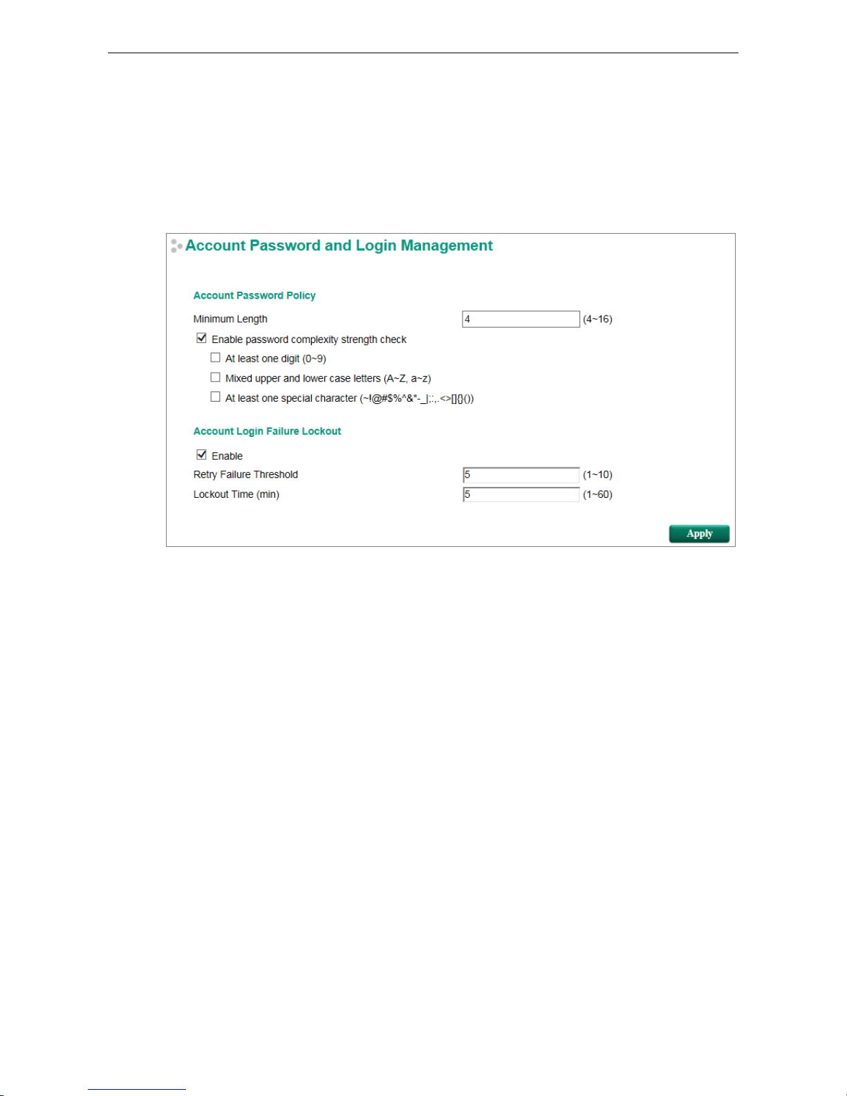
Password Login Policy
In order to prevent hackers from cracking the password, Moxa switches allow users to configure a password for
their account and lock the account in the event that the wrong password is entered. The account password
policy requires passwords to be of a minimum length and complexity with a strength check. If Account Login
Failure Lockout is enabled, you will need to configure the Retry Failure Threshold and Lockout Time
parameters. If the number of login attempts exceeds the Retry Failure Threshold, users will need to wait the
number of minutes configured in Lockout Time before trying again.
Network
Network configuration allows users to configure both IPv4 and IPv6 parameters for management access over
the network. The Moxa switch supports both IPv4 and IPv6, and can be managed through either of these
address types.
www.ipc2u.ru
www.moxa.pro
Page 19
PT-G7828/G7728 Featured Functions
3-7
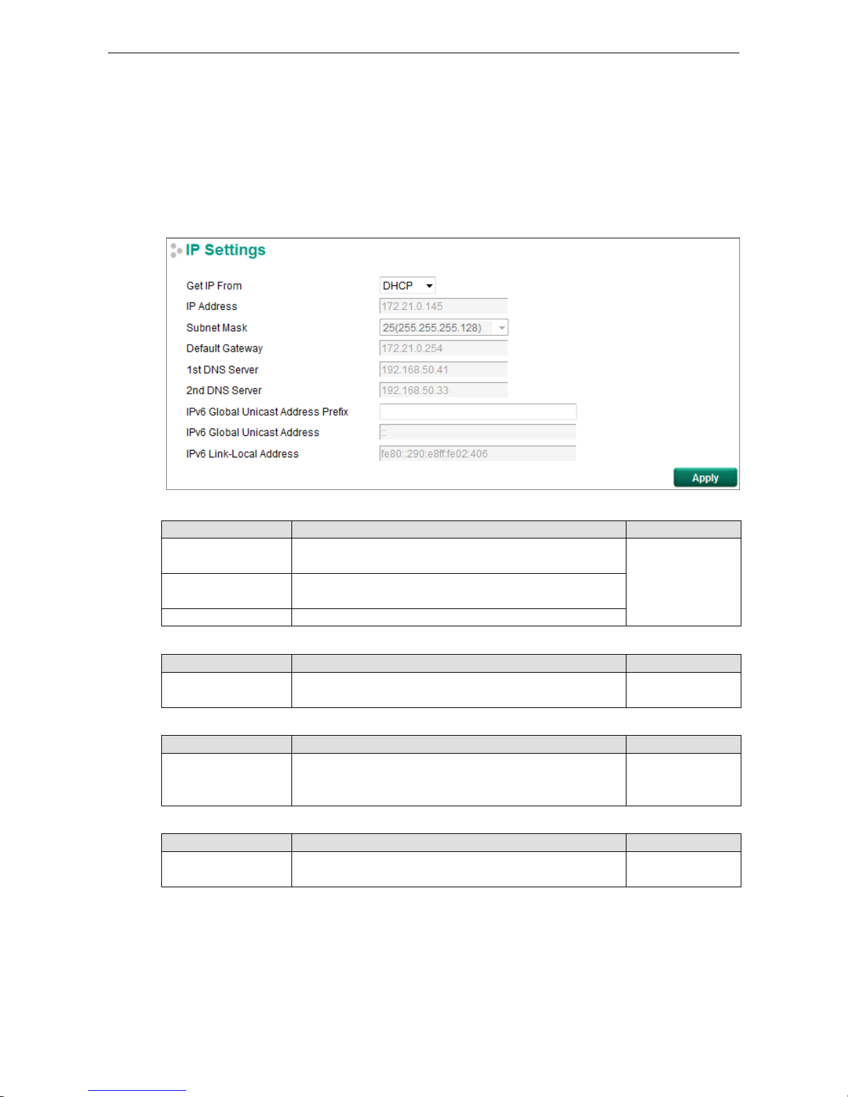
IP Settings
The IPv4 settings include the switch’s IP address and subnet mask, as well as the IP address of the default
gateway. In addition, input cells are provided for the IP addresses of a 1st and 2nd DNS server.
The IPv6 settings include two distinct address types—Link-Local Unicast addresses and Global Unicast
addresses. A Link-Local address makes the switch accessible over IPv6 for all devices attached to the same
local subnet. To connect to a larger network with multiple segments, the switch must be configured with a
Global Unicast address.
Get IP From
Setting Description Factory Default
DHCP The Moxa switch’s IP address
will be assigned automatically by
the network’s DHCP server.
Manual
BOOTP
The Moxa switch’s IP address will be assigned automatically by
the network’s BootP server.
Manual The Moxa switch’s IP address must be set manually.
IP Address
Setting Description Factory Default
IP address for the Moxa
switch
Assigns the Moxa switch’s IP address on a TCP/IP network. 192.168.127.253
Subnet Mask
Setting Description Factory Default
Subnet mask for the
Moxa switch
Identifies the type of network the Moxa
switch is connected to
(e.g., 255.255.0.0 for a Class B network, or 255.255.255.0 for
a Class C network).
24(255.255.255.0)
Default Gateway
Setting
Description
Factory Default
IP address for gateway Specifies the IP address of the router that connects
the LAN to
an outside network.
None
www.ipc2u.ru
www.moxa.pro
Page 20
PT-G7828/G7728 Featured Functions
3-8
DNS Server IP Addresses
Setting Description Factory Default
1st DNS Server Specifies the IP address of the DNS server used by your
network. After specifying the DNS server’s IP address, you can
use the Moxa switch’s URL (e.g., www.PT.company.com) to
open the web console instead of entering the IP address.
None
2nd DNS Server Specifies the IP address of the secondary DNS server used by
your network. The Moxa switch will use the secondary DNS
server if the first DNS server fails to connect.
None
IPv6 Global Unicast Address Prefix (Prefix Length: 64 bits) Default Gateway
Setting Description Factory Default
Global Unicast Address
Prefix
The prefix value must be formatted according to the RFC 2373
“IPv6 Addressing Architecture,” using 8 colon-separated 16-
bit
hexadecimal values. One double colon may be used in the
address to indicate the appropriate number of zeros required to
fill the undefined fields.
None
IPv6 Global Unicast Address
Setting Description Factory Default
None
Displays the IPv6 Global Unicast address. The network portion
of the Global Unicast address can be configured by specifying
the Global Unicast Prefix and using an EUI-64 interface ID in
the low order 64 bits. The host portion of the Global Unicast
address is automatically generated using the modified EUI-64
form of the interface identifier (Switch’s MAC address).
None
IPv6 Link-Local Address
Setting Description Factory Default
None The network portion of the Link-
Local address is FE80 and the
host portion of the Link-Local address is automatically
generated using the modified EUI-64 form of the interface
identifier (Switch’s MAC address).
None
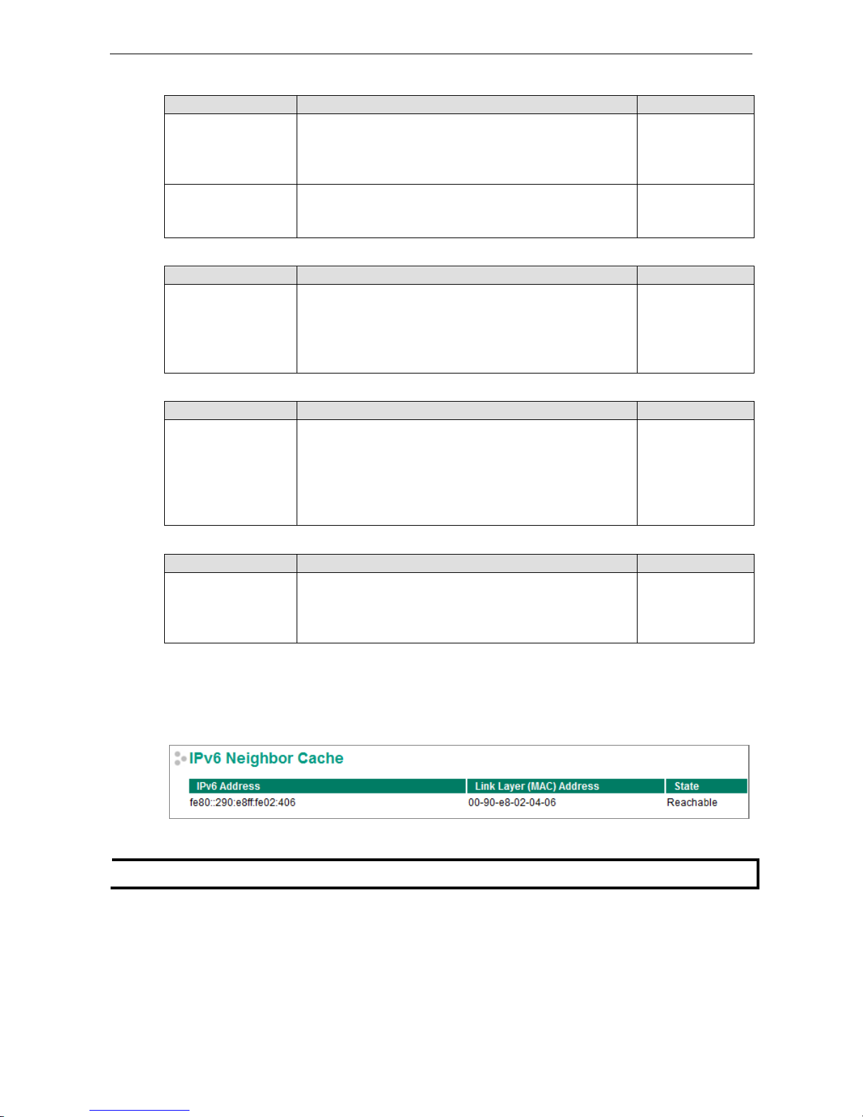
IPv6 Neighbor Cache
The IPv6 neighbor cache includes the neighboring node’s IPv6 address, the corresponding Link-Layer address,
and the current state of the entry.
NOTE
The
IPv6 feature only works on the PT-G7728.
www.ipc2u.ru
www.moxa.pro
Page 21
PT-G7828/G7728 Featured Functions
3-9
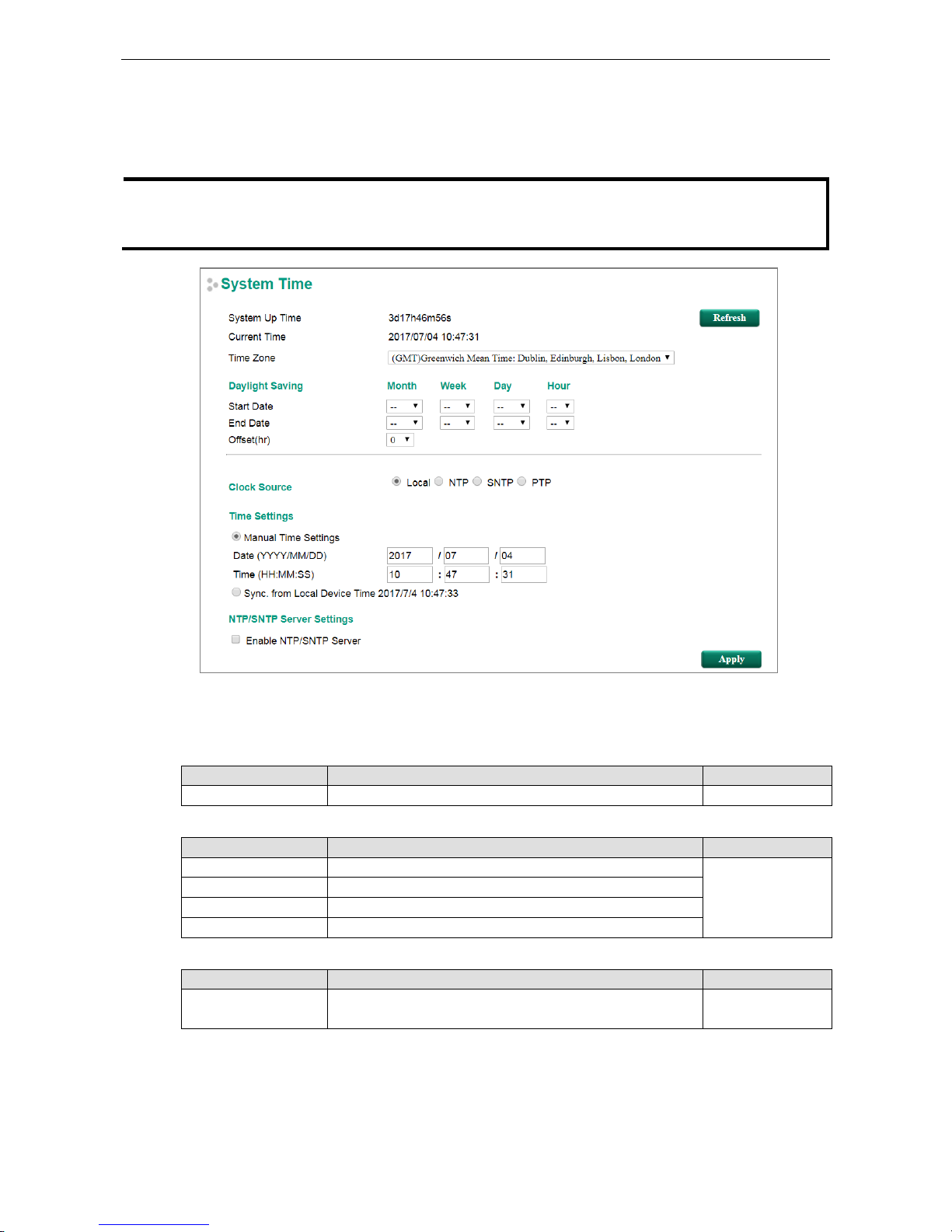
Date and Time
The Moxa switch has a time calibration function based on information from an NTP server or user specified time
and date, allowing functions such as automatic warning emails to include a time and date stamp.
NOTE
The user must update t
he Current Time and Current Date after powering off the switch for a long period o
f
time (for example a few days). The user must pay particular attention to this when there is no time server,
LAN
, or Internet connection.
o
System Up Time
Indicates how long the Moxa switch has been up and running since the last cold start.
Current Time
Setting Description Factory Default
User-specified time Indicates time in yyyy-mm-dd format. None
Clock Source
Setting Description Factory Default
Local Configure clock source from local time Local
NTP Configure clock source from NTP
SNTP Configure clock source from SNTP
PTP Configure clock source from PTP
Time Zone
Setting Description Factory Default
Time zone Specifies the time zone, which is used to determine the local
time offset from GMT (Greenwich Mean Time).
GMT (Greenwich
Mean Time)
Daylight Saving Time
The Daylight Saving Time settings are used to automatically set the Moxa switch’s time ahead according to
national standards.
www.ipc2u.ru
www.moxa.pro
Page 22

PT-G7828/G7728 Featured Functions
3-10
Start Date
Setting Description Factory Default
User-specified date Specifies the date that Daylight Saving Time begins. None
End Date
Setting Description Factory Default
User-specified date Specifies the date that Daylight Saving Time ends. None
Offset
Setting Description Factory Default
User-specified hour Specifies the number of hours that the time should be set
forward during Daylight Saving Time.
None
NOTE
Changing the time zone will automatically correct the current time. Be sure to set the time zone before setting
the time.
If the NTP or SNTP options are enabled, you will also need to configure the following settings.
Time Server IP / Name
Setting Description Factory Default
1st
address or name of
IP server
The IP or domain address (e.g., 192.168.1.1,
time.stdtime.gov.tw, or time.nist.gov).
None
IP address or name of
secondary time server
The Moxa switch will try to locate the secondary S
NTP server if
the first SNTP server fails to connect.
Query Period The time period to sync with time server 600secs
Enable NTP/SNTP Server
Setting Description Factory Default
Enable/Disable
Enables SNTP/NTP server functionality for clients
Disabled
NTP Authentication Settings
NTP authentication is used to authenticate the NTP time synchronization packet. When you enable the NTP
authentication, the device synchronizes to a time source/client/peer only if the packet carries the
authentication key. The device will drop the packet that fails the authentication and will not update the local
time.
www.ipc2u.ru
www.moxa.pro
Page 23

PT-G7828/G7728 Featured Functions
3-11
Setting Description
Enable NTP authentication The NTP authentication will be enabled if the checkbox
is selected
Authentication Key:
This part indicates the key that can be recognized by this device, and a maximum of 5 keys can be stored in the
device. Users can activate the key by selecting the ‘Trusted’ checkbox.
Setting Description
Key ID Indicate the ID of the key
Range: 1 to 65535,
Maximum of 5 key IDs can be stored
Key String Defines the authentication key
Trusted If selected, the key will be activated
NTP Client Settings
Setting Description
Time Server/Peer Address The time server or peer to sync to the ntp
Authentication Enter the key ID that you want to be used for authentication. The
authentication key that user wants to be used to set the time
NTP/SNTP Server settings
Setting Description
Enable NTP/SNTP Server The device will be the NTP server if the checkbox selected.
IEEE 1588
The following information is taken from the NIST website at http://ieee1588.nist.gov/intro.htm:
“Time measurement can be accomplished using the IEEE Standard for a Precision Clock Synchronization
Protocol for Networked Measurement and Control Systems (IEEE 1588-2008) to synchronize real-time clocks
incorporated within each component of the electrical power system for power automation applications.
IEEE 1588, which was published in November 2002, expands the performance capabilities of Ethernet networks
to control systems that operate over a communication network. In recent years an increasing number of
electrical power systems have been using a more distributed architecture with network technologies that have
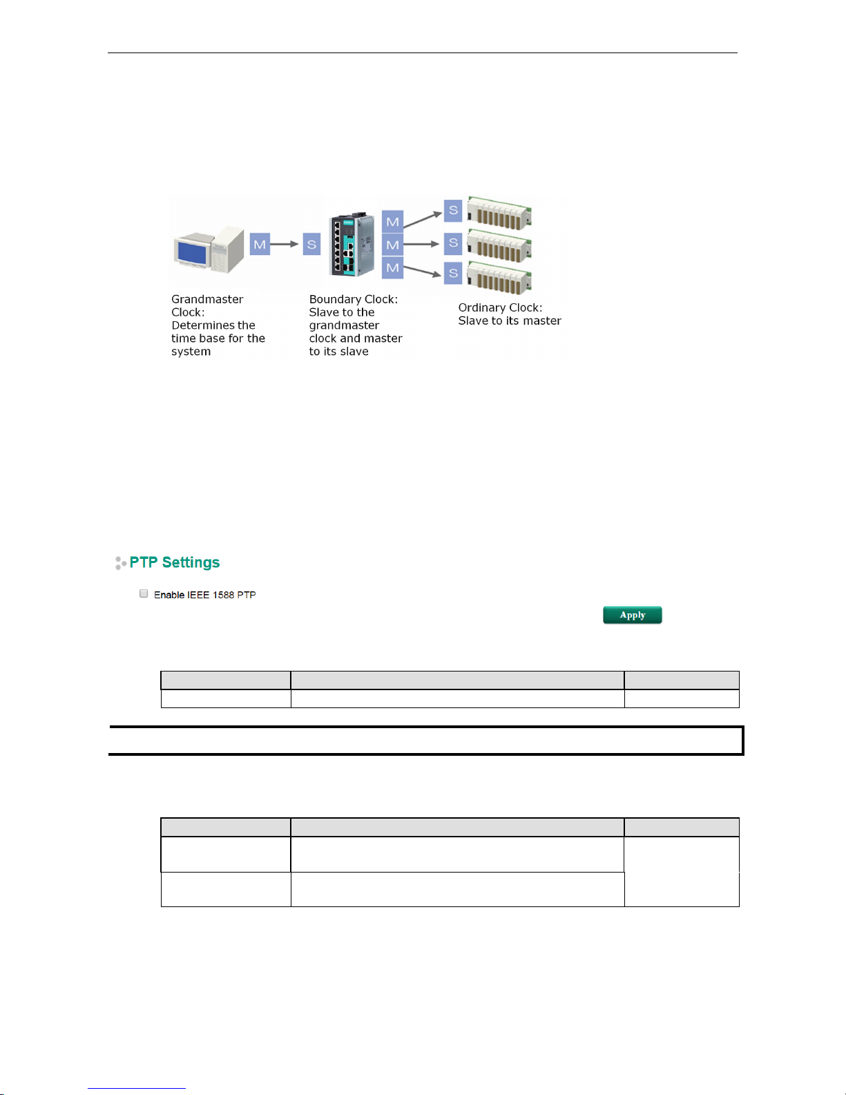
less stringent timing specifications. IEEE 1588 generates a master-slave relationship between the clocks, and
enforces the specific timing requirements in such power systems. All devices ultimately get their time from a
clock known as the grandmaster clock. In its basic form, the protocol is intended to be administration free.”
How Does an Ethernet Switch Affect 1588 Synchronization?
The following content is taken from the NIST website at http://ieee1588.nist.gov/switch.htm:
“An Ethernet switch potentially introduces multi-microsecond fluctuations in the latency between the 1588
grandmaster clock and a 1588 slave clock. Uncorrected these fluctuations will cause synchronization errors.
The magnitude of these fluctuations depends on the design of the Ethernet switch and the details of the
communication traffic. Experiments with prototype implementations of IEEE 1588 indicate that with suitable
care the effect of these fluctuations can be successfully managed. For example, use of appropriate statistics in
the 1588 devices to recognize significant fluctuations and use suitable averaging techniques in the algorithms
controlling the correction of the local 1588 clock will be good design means to achieve the highest time
accuracy.”
www.ipc2u.ru
www.moxa.pro
Page 24
PT-G7828/G7728 Featured Functions
3-12
Can Ethernet switches be designed to avoid the effects of these
fluctuations?
A switch can be designed to support IEEE 1588 while avoiding the effects of queuing. In this case two
modifications to the usual design of an Ethernet switch are necessary:
1. The Boundary Clock and Transparent Clock functionalities defined by IEEE 1588 must be implemented
in the switch.
2. The switch must be configured so that it does not pass IEEE 1588 message traffic using the normal
communication mechanisms of the switch.
Such an Ethernet switch will synchronize clocks directly connected to one of its ports to the highest possible
accuracy.
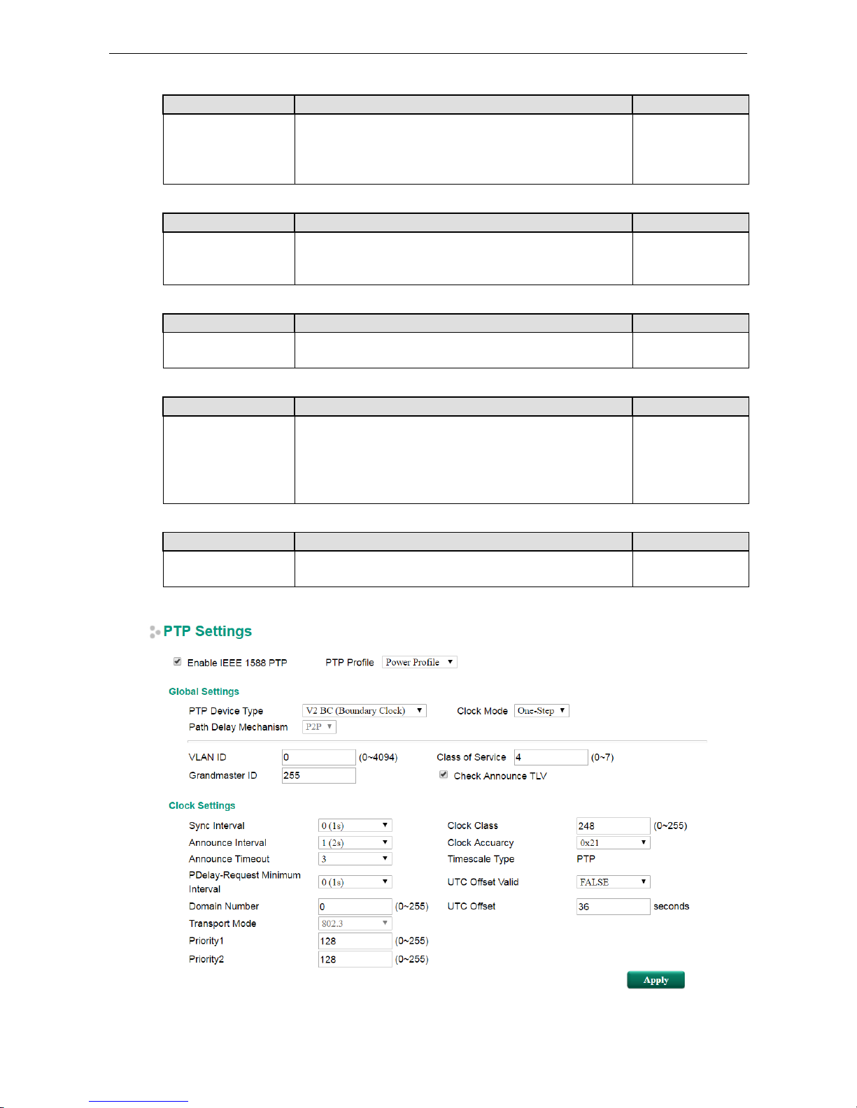
PTP Settings
Enable IEEE 1588 PTP
Setting Description Factory Default
Enable/Disable Enable or disable the IEEE 1588 PTP feature globally. Disabled
NOTE
When using IEEE 1588 PTP, please go to PTP port settings to enable
the PTP feature on each port as well.
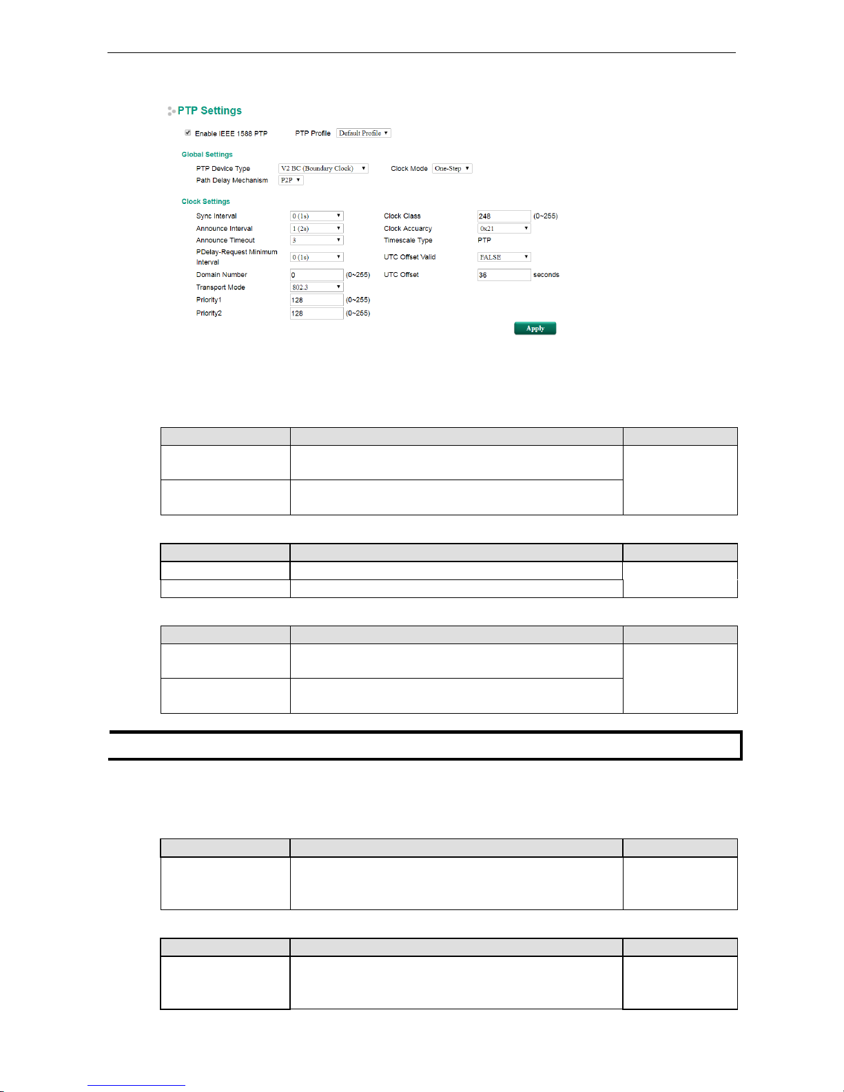
PTP Profile
Setting Description Factory Default
Default Profile Configure as 'PTP default profile' which is defined in IEEE Std
1588-2008, Annex J.
Default Profile
Power Profile Configure as 'PTP power profile' which is defined in IEEE
C37.238-2011.
www.ipc2u.ru
www.moxa.pro
Page 25
PT-G7828/G7728 Featured Functions
3-13
Default profile
Global settings
PTP Device Type
Setting Description Factory Default
V2 BC (Boundary
Clock)
Operates as an IEEE 1588 PTP v2 boundary clock. V2 TC (Transparent
Clock)
V2 TC (Transparent
Clock)
Operates as an IEEE 1588 PTP v2 transparent clock.
Clock Mode
Setting Description Factory Default
One-step Configure as a one-step clock. One-step
Two -step Configure as a two-step clock.
PTP Delay Mechanism
Setting Description Factory Default
P2P Configure as the peer-to-peer method. Power profile
(C37.238)
requires the peer-to-peer method.
P2P
E2E Configure as the end-to-end method, which measures the
propagation time between two PTP ports.
NOTE
Please make sure all PTP devices are configured to the same PTP Delay Mechanism.
Clock settings
Sync Interval
Setting Description Factory Default
-3 (128ms), -2
(256ms), -1 (512ms),
0 (1 sec), 1 (2 sec)
Configure synchronization message time interval. 0 (1 sec)
Announce Interval
Setting Description Factory Default
0 (1 sec), 1 (2 sec), 2
(4 sec), 3 (8 sec), 4 (16
sec)
Configure the mean time interval between successive
Announce messages.
1 (2 sec)
www.ipc2u.ru
www.moxa.pro
Page 26
PT-G7828/G7728 Featured Functions
3-14
Announce Timeout
Setting Description Factory Default
2 to 10 (times
announce interval)
Configure the number of Announce Interval messages that
were not received, before the master clock changes.
3
PDelay-Request Minimum Interval
Setting
Description
Factory Default
-1 (512ms), 0 (1 sec),
1 (2 sec), 2 (4 sec), 3
(8 sec), 4 (16 sec), 5
(32 sec)
Configure the minimum permitted mean time interval between
successive Pdelay_Req messages of the P2P mode.
0 (1 sec)
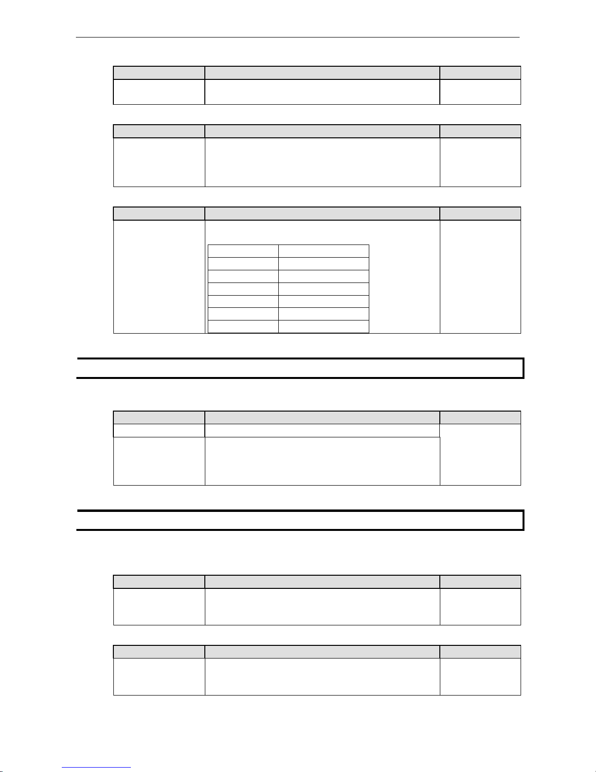
Domain Number
Setting Description Factory Default
0 to 255 A domain defines the scope of communication, state,
operations, data sets, and timescale of the the PTP message.
Value(decimal) Definition
0 Default domain
1 Alternate domain 1
2 Alternate domain 2
3 Alternate domain 3
4 to 127 User-defined domains
128 to 255
Reserved
0
NOTE
The switch and the grandmaster clock must be in the same PTP domain.
Transport Mode
Setting Description Factory Default
802.3 Configure PTP implementations directly using Ethernet format. Default Profile:
802.3;
Power Profile: fixed
to 802.3 as C37.238
required
IPv4 Configure PTP implementations using UDP/IPv4 as a
communication service.
NOTE
Please make sure all PTP devices are using the same communication service.
Priority1
Setting Description Factory Default
0 to 255 Lower values take precedence. PTP power profile (C37.238)
defines that value 128 is for grandmaster-capable devices;
Value 255 is only for slave devices.
128
Priority2
Setting Description Factory Default
0 to 255 Lower values take precedence. PTP power profile (C37.238)
defines that value 128 is for grandmaster-capable device;
Value 255 is only for slave devices.
128
www.ipc2u.ru
www.moxa.pro
Page 27
PT-G7828/G7728 Featured Functions
3-15
Clock Class
Setting Description Factory Default
0 to 255 The clock class attribute of an ordinary or boundary clock
denotes the traceability of the time or frequency
distributed by
the grandmaster clock. Value 248 is used as default if none of
the other clock class definitions a p p l y.
248
Clock Accuracy
Setting Description Factory Default
0x20 to 0x31, 0xFE The clock accuracy indicates the expected accuracy of a clock
when it is the grandmaster.
IEEE 1588 PTP defines value 0x21
for time accuracy within 100ns. The value 0xFE is for unknown.
0x21 (100 ns)
Timescale Type
Setting Description Factory Default
PTP Under normal operations, the epoch is the PTP epoch.
The time
unit is SI (International System) seconds.
PTP
UTC Offset Valid
Setting Description Factory Default
FALSE/TRUE In PTP systems whose epoch is the PTP epoch, the value of
UTC
offset is the offset between TAI (International Atomic Time)
and
UTC (Coordinated Universal Time). The value of the
UTC offset
is TRUE if the UTC offset is known to be correct; otherwise, it is
FALSE.
FALSE
UTC Offset
Setting Description Factory Default
0 to 65535 seconds The offset between the UTC clock and TAI is 37 seconds @ Jan,
2017
37
Power Profile
www.ipc2u.ru
www.moxa.pro
Page 28
PT-G7828/G7728 Featured Functions
3-16
Global settings
VLAN ID
Setting Description Factory Default
0 to 4094 Only available in Power Profile mode. The reserved value 0
indicates that only the priority tag in 802.1Q is considered.
This
value should be match to VLAN rules where the enabled PTP
feature applies to the whole system. Please also take note of
the VLAN setting of the device.
0
Class of Service
Setting Description Factory Default
0 to 7 Only available in Power Profile mode. Configure as an 802.1p
priority tag. Lower values take precedence.
4
Grandmaster ID
Setting Description Factory Default
0 to 255 Only available in Power Profile mode.
Configure grandmaster ID
to identify the grandmaster clock source.
255
Check Announce TLV
Setting Description Factory Default
Enable/Disable Only available in Power Profile mode. When the profile type is
Power profile, the switch will not handle the PTP announce
messages which do not include length and value (TLV)
extensions: Organization_extension and Alternate_timescale.
Configure 'Check announce TLV' to enable or disable announce
TLV checking.
Enabled
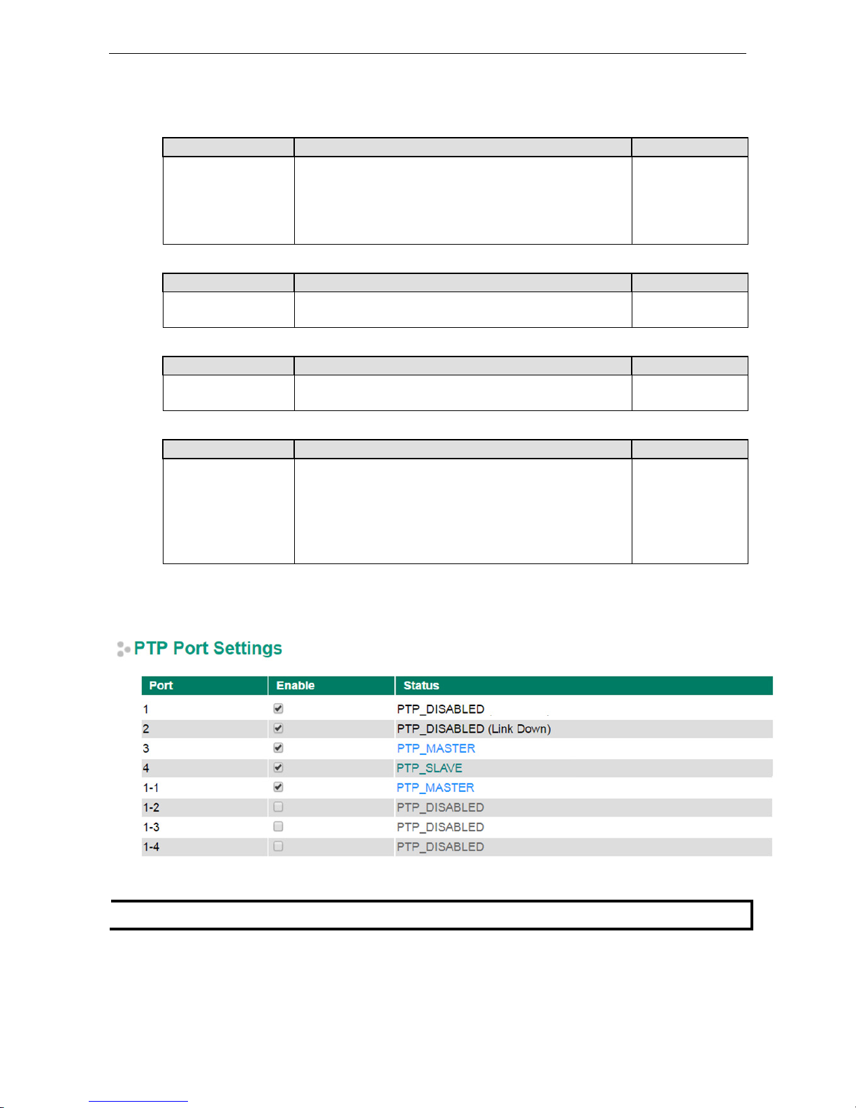
PTP Port Settings
NOTE
When enabl
ing the PTP feature on each port, please also enable the ‘Enable IEEE 1588 PTP’ on ‘PTP settings’
.
www.ipc2u.ru
www.moxa.pro
Page 29
PT-G7828/G7728 Featured Functions
3-17
PTP Port settings
Setting Description Factory Default
Enable/Disable PTP port status:
•
PTP_INITIALIZING
: PTP port is initializing. No PTP messages
on its communication path.
•PTP_MASTER: The port is the source of time on the path
served by the port.
•PTP_DISABLED: A port in this state will not handle any PTP
received messages except for management messages.
•
PTP_PASSIVE:
The port is not the master on the path nor does
it synchronize to a master.
•PTP_LISTENING: The port is waiting for the announce time
out
interval to expire or to receive an Announce message from a
master.
•PTP_SLAVE: The port is synchronizing to the selected PTP
master port.
PTP disabled
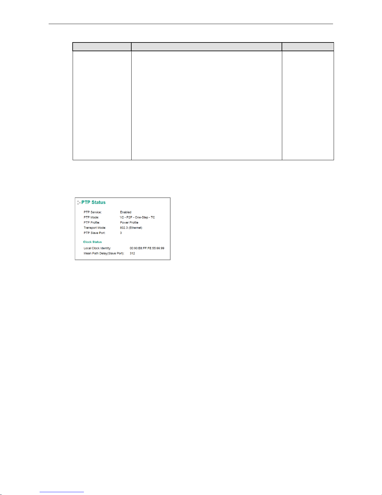
PTP Status
Indicates the current IEEE 1588 PTP status.
Warning Notification
Since industrial Ethernet devices are often located at the endpoints of a system, these devices will not always
know what is happening elsewhere on the network. This means that an industrial Ethernet switch that connects
to these devices must provide system maintainers with real-time alarm messages. Even when control
engineers are out of the control room for an extended period of time, they can still be informed of the status of
devices almost instantaneously when exceptions occur. The Moxa switch supports different approaches to warn
engineers automatically, such as email, trap, syslog and relay output. It also supports two digital inputs to
integrate sensors into your system to automate alarms by email and relay output.
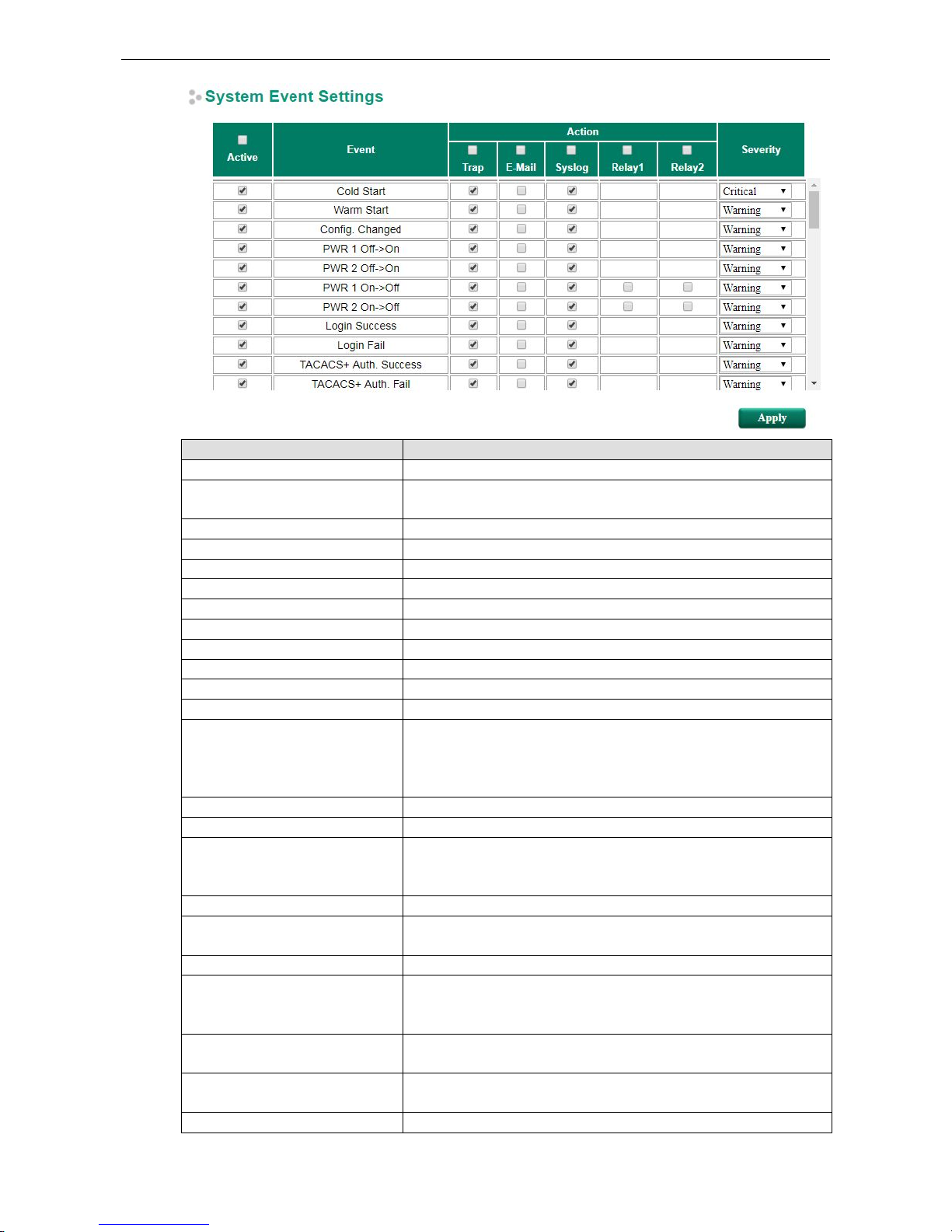
System Event Settings
System Events are related to the overall function of the switch. Each event can be activated independently with
different warning approaches. The Administrator can decide the severity of each system event.
www.ipc2u.ru
www.moxa.pro
Page 30
PT-G7828/G7728 Featured Functions
3-18
System Events Description
Cold Start Power is cut off and then reconnected.
Warm Start The Moxa switch is rebooted, such as when network parameters are
changed (IP address, subnet mask, etc.).
Configuration Change Any configuration item has been changed.
Power Transition (OnOff)
The Moxa switch is powered down.
Power Transition (OffOn)
The Moxa switch is powered up.
Login Success The account logins to the switch
Login Fail An incorrect password was entered.
TACACS+ Auth. Success The account is authorized by a TACACS+ server
TACACS Auth. Fail Incorrect authentication details were entered
RADIUS Auth. Success The account is authorized by a RADIUS server
RADIUS Authentication Fail Incorrect authentication details were entered
Password Change User changes the account password
Topology Changed • If the Master of the Turbo Ring has changed or the backup path is
activated
• If the Turbo Ring path is disconnected
• If the MSTP topology has changed
Coupling Changed Backup path is activated
Master Changed Master of the Turbo Ring has changed
Master Mismatch When the duplicate master (two or more) or non-master is set up, if any
Turbo Ring path/switch fails, the duplicate master switches will
automatically renegotiate to determine a new master.
RSTP Root Changed If the RSTP root has changed
RSTP Topo. Changed If any Rapid Spanning Tree Protocol switches have changed their
position (applies only to the root of the tree)
Turbo Ring Break Turbo Ring path is disconnected
ABC-02 Status Detects if the ABC-02-USB-
T is connected or disconnected to the switch
when the ABC-02-USB-T automatically imports/exports/backs-up the
configuration
Rate Limited On (Disable Port) When the port is disabled due to the ingress throughput exceeding the
configured rate limit.
Rate Limited Off (Disable Port) The port disable function is off because it exceeds
the traffic duration or
the user changes “Port Disable” mode to “Drop Packet” mode.
Port Looping Port looping event is triggered
www.ipc2u.ru
www.moxa.pro
Page 31

PT-G7828/G7728 Featured Functions
3-19
System Events Description
LLDP Table Change Nearly connected devices are changed and shown in the LLDP table
Login Failure Lockout The attempt to log in exceeds the threshold
Account Info Changed The account information has been changed
Configuration is Imported When the configuration is successfully imported
SSL Certification is Imported When SSL Certification is successfully imported
Fiber Check Warning If the corresponding value of the fiber port status exceeds the
threshold
defined by the Fiber Check function
MAC Sticky Violation Port Disable Any port with MAC sticky function is disabled because of a rule violation
Port module inserted The module is inserted to the system
Port module removed The module is removed from the system
Port module unrecognized The module inserted is not recognized by the system
Dual image fail One of the image has failed
Tracking Status Changed The tracking status has changed
Port Enable Tracking Changed The tracking status has changed and reacts on Port Enable
Static Route Tracking Changed The tracking status has changed and reacts on Static Route
VRRP Tracking Changed The tracking status has changed and reacts on VRRP priority
EPS Off->On The external power supply for PoE is on
EPS On->Off The external power supply for PoE is off
GOOSE Check Event The GOOSE check status has changed
Dying Gasp When power input of power module is lower the system uptime threshold
the dying gasp function will be activated. This event will only activate
before the whole system powers off.
Four response actions are available when events are triggered.
Action Description
Trap
A notification will be sent to the trap server when an event is triggered.
E-Mail A notification will be sent to the email server defined in the Email Setting.
Syslog A notification will be sent to the syslog server defined in Syslog Server Setting.
Relay Supports digital inputs to integrate sensors. When an event is triggered, the device will
automate alarms through the relay output.
Severity
Severity Description
Emergency System is unusable
Alert Action must be taken immediately
Critical Critical conditions
Error Error conditions
Warning Warning conditions
Notice Normal but significant condition
Information Informational messages
Debug Debug-level messages
www.ipc2u.ru
www.moxa.pro
Page 32
PT-G7828/G7728 Featured Functions
3-20
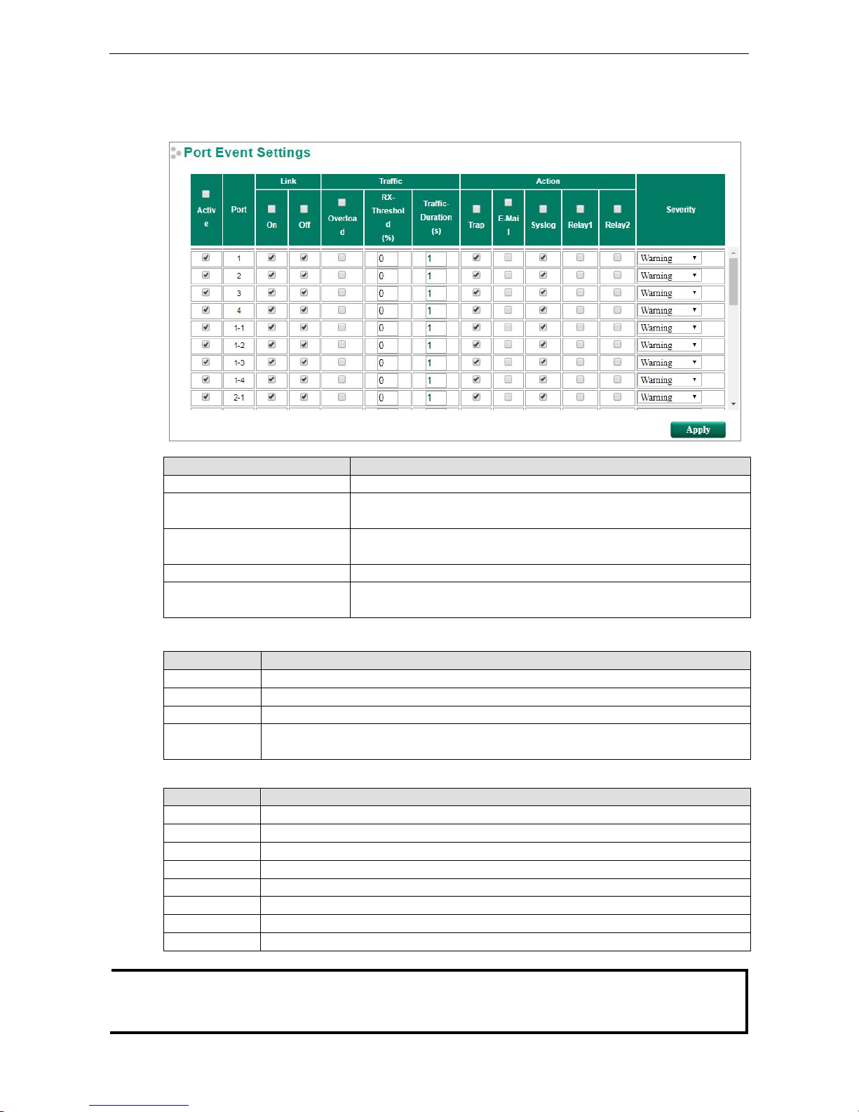
Port Event Settings
Port Events are related to the activity of a specific port.
Port Events Warning e-mail is sent when…
Link-ON The port is connected to another device.
Link-OFF The port is disconnected (e.g., the cable is pulled out, or the opposing
device shuts down).
Traffic-Overload The port’s traffic surpasses the Traffic-Threshold for that port (provided
this item is Enabled).
Traffic-Threshold (%) Enter a nonzero number if the port’s Traffic-Overload item is Enabled.
Traffic-Duration (sec.) A Traffic-Overload warning is sent every Traffic-Duration seconds if the
average Traffic-Threshold is surpassed during that time period.
Four response actions are available on the EDS E series when events are triggered.
Action Description
Trap A notification will be sent to the trap server when an event is triggered.
E-Mail A notification will be sent to the email server defined in the Email Setting.
Syslog A notification will be sent to the syslog server defined in Syslog Server Setting.
Relay Supports digital inputs to integrate sensors. When an event is triggered, the device will
automate alarms through the relay output.
Severity
Severity Description
Emergency System is unusable
Alert
Action must be taken immediately
Critical Critical conditions
Error Error conditions
Warning Warning conditions
Notice Normal but significant condition
Information Informational messages
Debug Debug-level messages
NOTE
The Traffic
-Overload, Traffic-Threshold (%), and Traffic-Duration (sec.) Port Event items are related. If
you
Enable the Traffic
-Overload event, then be sure to enter a nonzero Traffic-
Threshold percentage, as well as a
Traffic
-Duration between 1 and 300 seconds.
www.ipc2u.ru
www.moxa.pro
Page 33
PT-G7828/G7728 Featured Functions
3-21
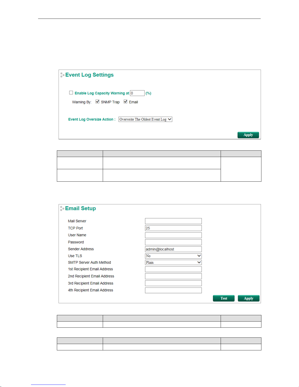
Event Log Settings
This function is used to inform the user what the event log capacity status is and decide what action to take
when an event log is oversized. Select the Enable Log Capacity Warning checkbox to set the threshold
percentage. When the event log capacity is over the percentage, the switch will send a warning message by
SNMP Trap or Email.
Event Log Oversize Action
Setting Description Factory Default
Overwrite The Oldest
Event Log
The oldest event log will be overwritten when the event log
exceeds 1000 records.
Overwrite The
Oldest Event Log
Stop Recording Event
Log
Additional events will not be recorded when the event log
exceeds 1000 records.
Email Settings
Mail Server
Setting Description Factory Default
IP address or url The IP Address or url of the email server. None
TCP Port
Setting Description Factory Default
TCP Port number The TCP port number of your email server. 25
www.ipc2u.ru
www.moxa.pro
Page 34
PT-G7828/G7728 Featured Functions
3-22
User Name
Setting Description Factory Default
Max. of 45 characters Your email account name None
Password Setting
Setting Description Factory Default
Password The email account password. None
Email Address
Setting Description Factory Default
Max. of 30 characters You can set up to 4 email addresses to receive alarm emails
from the Moxa switch.
None
Sender Address
Setting Description Factory Default
Max. 30 characters Sender Email Address admin@localhost
User TLS
Setting Description Factory Default
Yes/No
Enables TLS(Transport Layer Security)
No
SMTP Server Auth Method
Setting Description Factory Default
Plain/Login/
CRAM-MD5
choose an authentication mechanism, PLAIN, LOGIN, and
CRAM-MD5, to login SMTP Server
Plain
Sending a Test Email
After you complete the email settings, you should first click Apply to activate those settings, and then press
the Test button to verify that the settings are correct.
NOTE
Auto warning e
-mail mess
ages will be sent through an authentication protected SMTP server that supports
the CRAM
-MD5, LOGIN, and PAIN methods of SASL (Simple Authentication and Security Layer)
authentication mechanism.
We strongly recommend not entering your Account Name and Acco
unt Password if auto warning e-mail
messages can be delivered without using an authentication mechanism.
www.ipc2u.ru
www.moxa.pro
Page 35
PT-G7828/G7728 Featured Functions
3-23
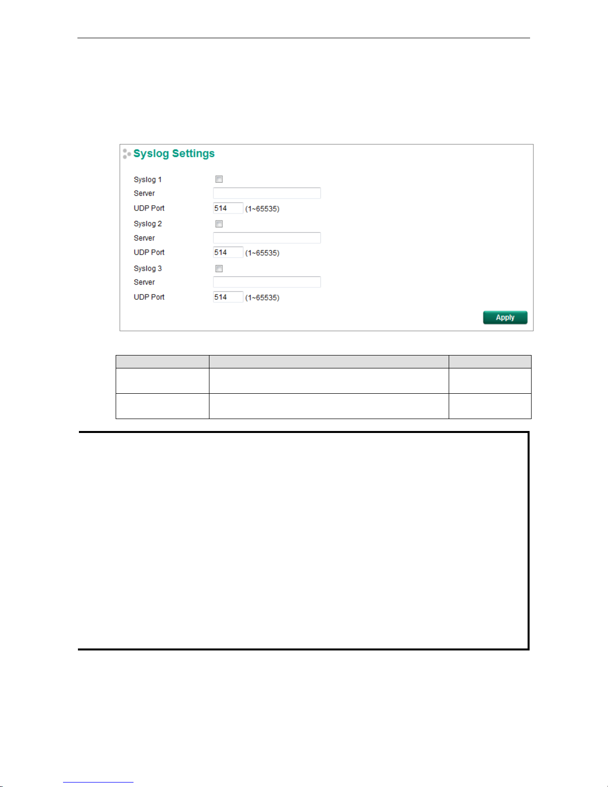
Syslog Server Settings
The Syslog function provides the event logs for the syslog server. The function supports 3 configurable syslog
servers and syslog server UDP port numbers. When an event occurs, the event will be sent as a syslog UDP
packet to the specified syslog servers. Each Syslog server can be activated separately by checking the
appropriate checkbox to enable it.
Syslog Server 1/2/3
Setting Description Factory Default
IP Address Enter the IP address of Syslog server 1/2/3, used by your
network.
None
Port Destination
(1 to 65535)
Enter the UDP port of Syslog server 1/2/3. 514
NOTE
The following events will be recorded into the Moxa switch’s Event Log table, and will then be
sent to the
specified Syslog Server:
•
Cold start
•
Warm start
•
Configuration change activated
•
Power 1 or 2 transition: Off to On or On to Off
•
Authentication fail
•
Password change
•
Redundancy protocol/topology change
•
Master setting mismatch
•
ABC-02 status
•
Web log in
•
Rate Limit on/off(Disable port)
•
Port looping
•
Port traffic overload
•
dot1x Auth Fail
•
Port link off/on
www.ipc2u.ru
www.moxa.pro
Page 36
PT-G7828/G7728 Featured Functions
3-24
Relay Warning Status
When a relay warning is triggered by either the system or port events, the administrator can turn off the
hardware warning buzzer by clicking the Apply button. The event will still be recorded in the event list.
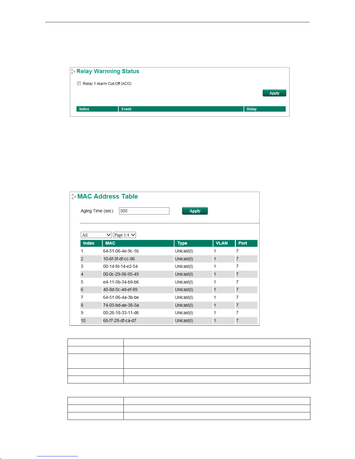
MAC Address Table
The MAC address table shows the MAC address list passed through the Moxa switch. The Aging Time (15 to
3825 seconds) defines the length of time that a MAC address entry can remain in the Moxa switch. When an
entry reaches its aging time, it “ages out” and is purged from the switch, effectively cancelling frame
forwarding to that specific port.
The MAC Address table can be configured to display the following Moxa switch MAC address groups, which are
selected from the drop-down list.
Drop Down List
ALL Select this item to show all of the Moxa switch’s MAC addresses.
ALL Learned Select this item to show all of the Moxa switch’s Learned MAC addresses.
ALL Static Select this item to show all of the Moxa switch’s Static, Static Lock, and Static
Multicast MAC addresses.
ALL Multicast Select this item to show all of the Moxa switch’s Static Multicast MAC addresses.
Port x Select this item to show all of the MAC address’s dedicated ports.
The table displays the following information:
MAC This field shows the MAC address.
Type This field shows the type of this MAC address.
Port This field shows the port that this MAC address belongs to.
www.ipc2u.ru
www.moxa.pro
Page 37
PT-G7828/G7728 Featured Functions
3-25
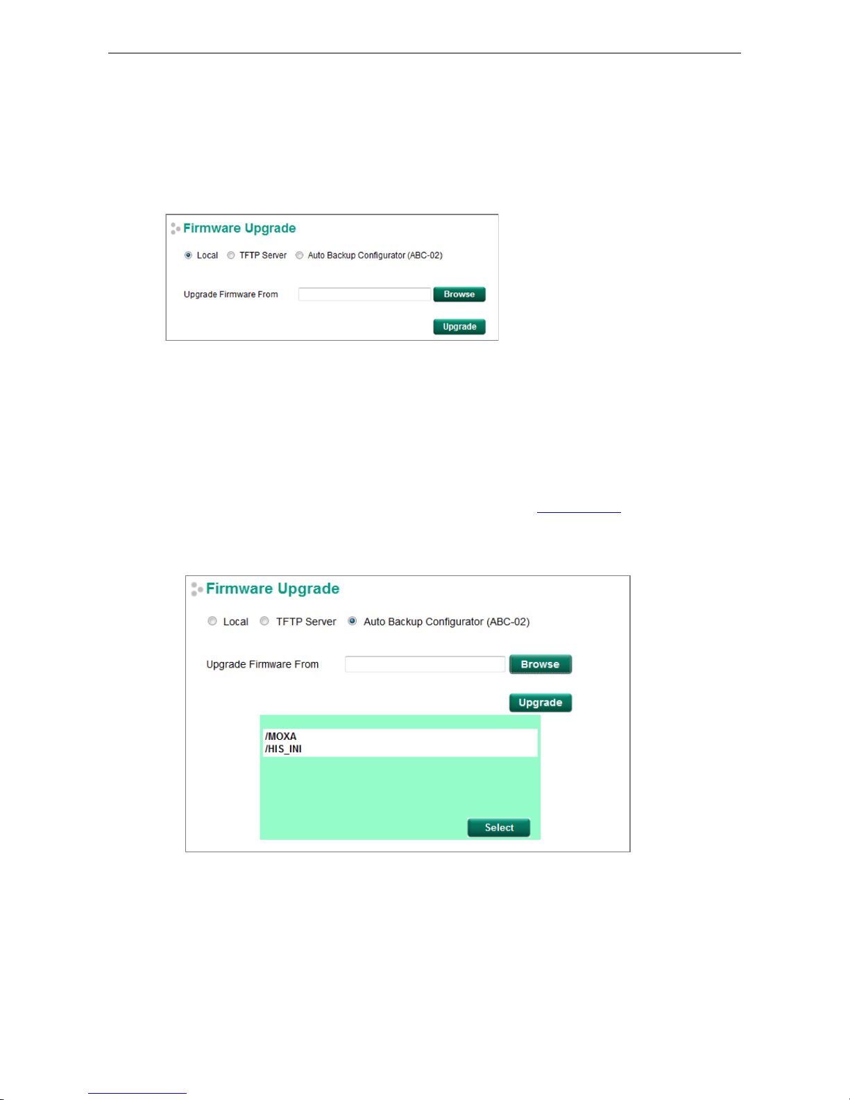
System Files
Firmware Upgrade
There are three ways to update your Moxa switch’s firmware: from a local *.rom file, by remote TFTP server,
and with Auto Backup Configurator (ABC-02).
Local
1. Download the updated firmware (*.rom) file from Moxa’s website (www.moxa.com).
2. Browse for the (*.rom) file, and then click the Upgrade button
TFTP Server
1. Enter the TFTP Server’s IP address.
2. Input the firmware file name (*.rom) and click the Upgrade button.
Auto Backup Configurator (ABC-02)
1. Download the updated firmware (*.rom) file from Moxa’s website (www.moxa.com).
2. Save the file to the ABC-02’s Moxa folder. The file name cannot be longer than 8 characters, and the file
extension must be .rom.
3. Browse for the firmware (*.rom) file from the ABC-02, and then click the Upgrade button.
www.ipc2u.ru
www.moxa.pro
Page 38
PT-G7828/G7728 Featured Functions
3-26
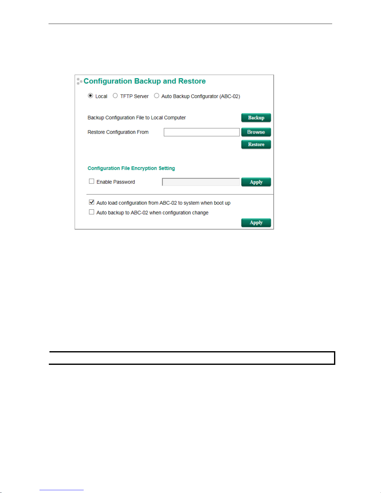
Configuration Backup and Restore
There are three ways to back up and restore your Moxa switch’s configuration: from a local configuration file,
by remote TFTP server, and with Auto Backup Configurator (ABC-02).
Local
1. Click the Backup button to back up the configuration file to a local drive.
2. Browse for a configuration on a local disk, and then click the Restore button.
TFTP Server
1. Enter the TFTP Server’s IP address.
2. Input the backup/restore file name (supports up to 54 characters, including the .ini file extension) and then
click the Backup/Restore button.
Auto Backup Configurator (ABC-02)
1. Click Backup to save the configuration file to the ABC-02. The file will be saved in the ABC-02’s Moxa folder
as a *.ini file (e.g., Sys.ini).
Note that two files will be saved to the ABC-02-USB’s Moxa folder: Sys.ini and MAC.ini. The purpose of
saving the two files is to identify which file will be used when Auto load configuration from ABC to
system when boot up is activated.
NOTE
MAC.ini is named using the last 6 digits of the switch’s MAC address, without spaces.
2. Click Browse to select the configuration file, and then click Restore to start loading the configuration into
your switch.
3. Configuration File Encryption Setting
Select the Configuration File Encryption Setting checkbox, input the password, and then click Apply.
4. Auto load configuration from ABC to system when boot up
Select the Auto load configuration from ABC to system when boot up checkbox and then click Apply.
Note that this function is enabled by default.
Power off your switch first, and then plug in the ABC-02. When you power on your switch, the system will
detect the configuration file on the ABC-02 automatically. The switch will recognize the file name, with the
following sequence priority:
www.ipc2u.ru
www.moxa.pro
Page 39
PT-G7828/G7728 Featured Functions
3-27
First priority: MAC.ini
Second priority: Sys.ini
If no matching configuration file is found, the fault LED light will turn on, and the switch will boot up
normally.
NOTE
MAC.ini is named using the last 6 digits of the switch’s MAC address, without spaces.
5. Auto backup to ABC-02 when configuration changes
Select the Auto backup to ABC-02 when configuration change checkbox and then click Apply. This
function is disabled by default.
The ABC-02 is capable of backing up switch configuration files automatically. While the ABC-02 is plugged
into the switch, enable the Auto backup to ABC-02 when configuration change option, and then click
Apply. Once this configuration is modified, the switch will back up the current configuration to the /His_ini
folder on the ABC-02. The file name will be the system date/time (MMDDHHmm.ini).
NOTE
MM=month, DD=day, HH=
hour, mm=minutes, from the system time.
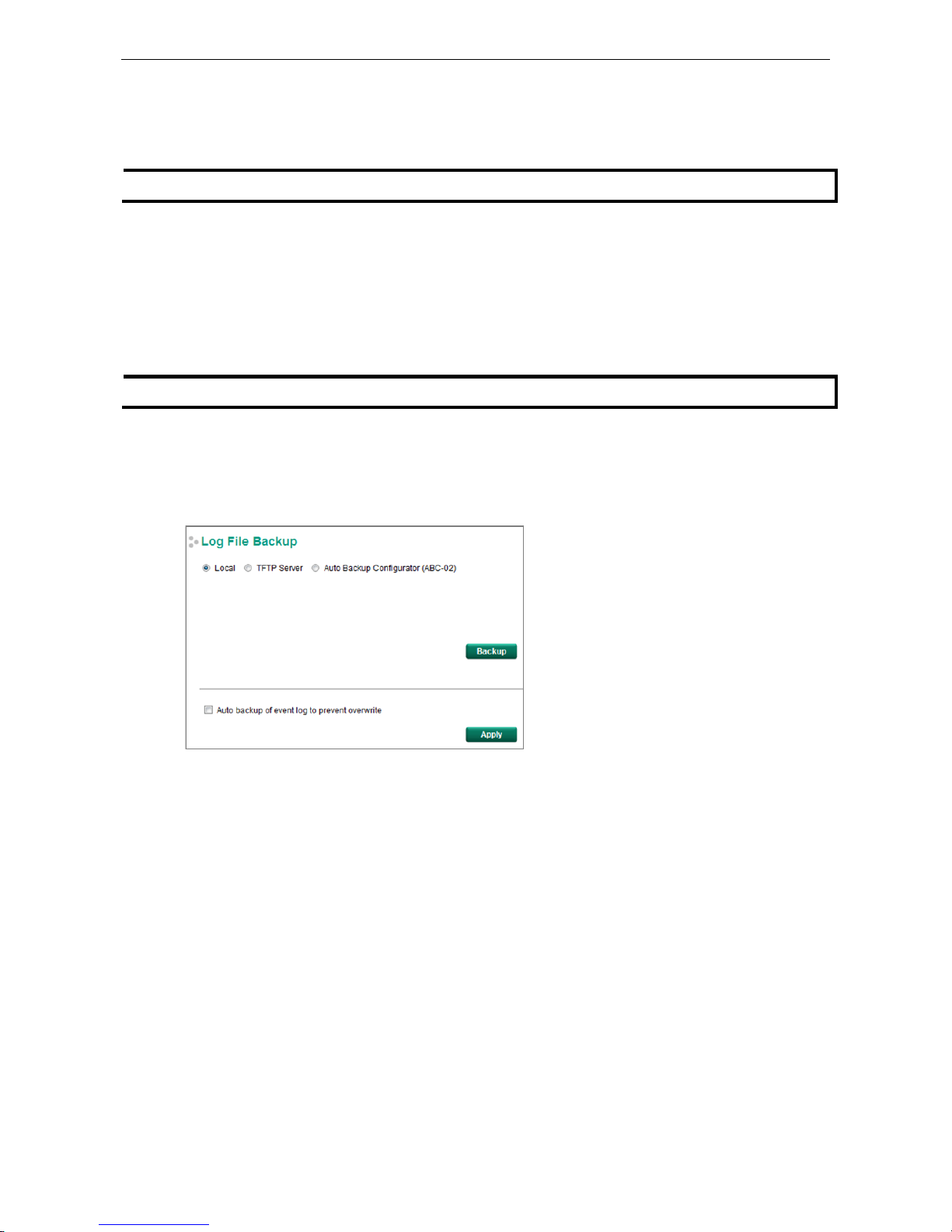
Log File Backup
There are three ways to back up Moxa switch’s log files: from a local drive, by remote TFTP server, or with Auto
Backup Configurator (ABC-02).
Local
Click the Backup button to back up the log file to a local drive.
TFTP Server
Enter the TFTP Server’s IP address and file name and then click the Backup button.
Auto Backup Configurator (ABC-02)
Click Backup to save the configuration file to the ABC-02. The file will be saved in the ABC-02’s Moxa folder
with filename Sys.ini.
Auto backup of event log to prevent overwrite
This function is designed to maintain a long-term record of the switch’s log files. Moxa Ethernet switches are
capable of saving 1000 event log entries. When the 1000-entry storage limit is reached, the switch will delete
the oldest saved event log. The ABC-02 can be used to back up these event logs. When the number of switch
log entries reaches 1000, the ABC-02 will save the oldest 100 entries from the switch.
Enable the Auto backup of event log to prevent overwrite, and then click Apply. After that, when the
ABC-02 is plugged into the switch, the event logs will always be saved to the ABC-02 automatically when the
number of switch log entries reaches 1000. Each backup action saves the oldest 100 logs to the ABC-02 in one
file, with the filename generated by the current system time as MMDDHHmm.ini. The file is saved to the
His_log folder.
www.ipc2u.ru
www.moxa.pro
Page 40
PT-G7828/G7728 Featured Functions
3-28
NOTE
Note: MM=month, DD=day, HH=hour, mm=minutes, from
the system time.
The log file includes the following information:
Index An event index assigned to identify the event sequence.
Bootup
Number
This field shows how many times the Moxa switch has been rebooted or cold started.
Date The date is updated based on how the current date is set on the System Settings page.
Time The time is updated based on how the current time is set on the System Settings page.
System
Startup Time
The system startup time related to this event.
Event Events that have occurred.
Switch Reset Button
The Moxa switch reset button can be used to perform two functions: quickly reset the switch’s configuration
and save the current configuration and log files to the ABC-02. Please refer to the QIG for how to use the
ABC-02.
NOTE
DO NOT remove the ABC
-02 when performing an upgrade, backup, or restore.
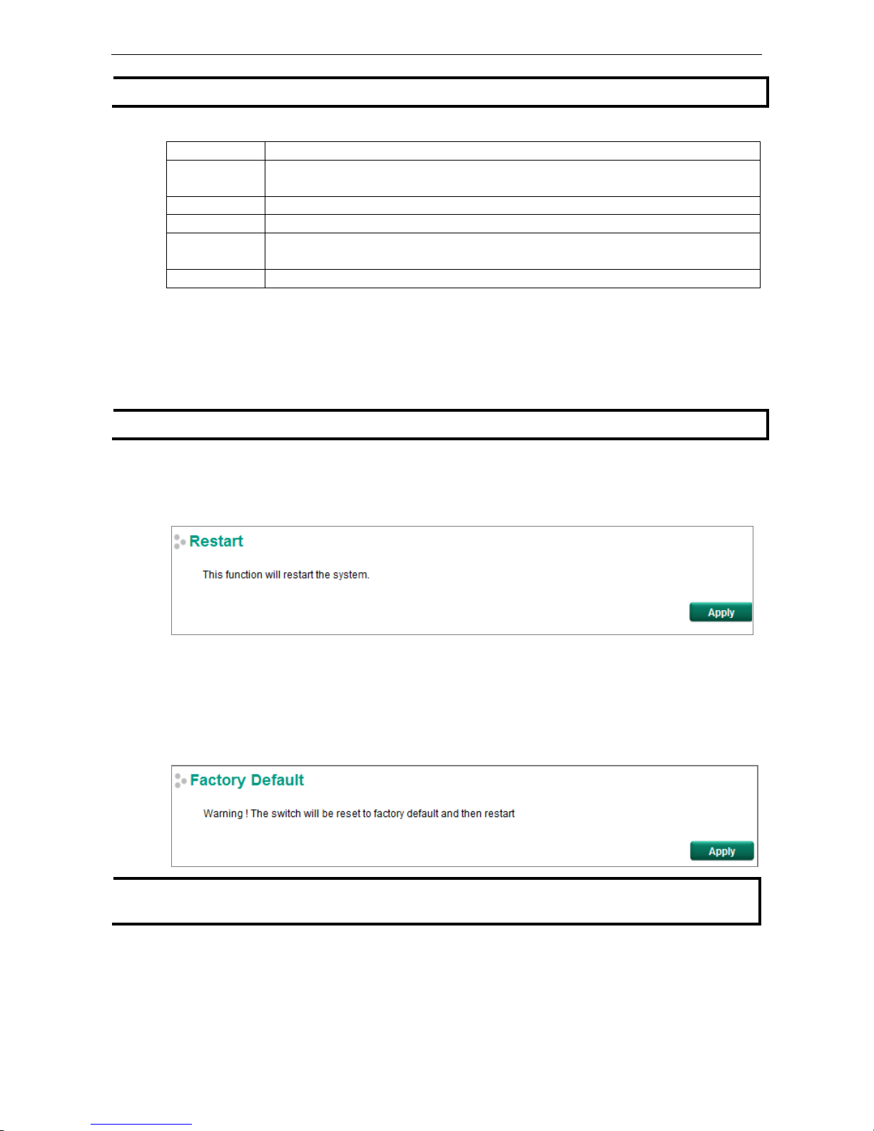
Restart
The Restart function provides users with a quick way to restart the switch’s operating system.
Factory Default
The Factory Default function provides users with a quick way of restoring the Moxa switch’s configuration to
factory defaults. The function can be activated from the USB serial interface, via Telnet, through the web-based
console, or with the hardware reset button.
NOTE
After restoring the factory default configuration, you will need to use the default network settings to
re
-establish the web or Telnet console connection with the Moxa switch.
www.ipc2u.ru
www.moxa.pro
Page 41
PT-G7828/G7728 Featured Functions
3-29
PoE (PoE Models Only)
Power over Ethernet has become increasingly popular, due in large part to the reliability provided by PoE
Ethernet switches that supply the power to Powered Devices (PD) when AC power is not available, or is too
expensive to provide locally.
Power over Ethernet can be used with the following types of devices:
• Surveillance cameras
• Security I/O sensors
• Industrial wireless access points
• Emergency IP phones
In fact, it’s not uncommon for video, voice, and high-rate industrial application data transfers to be integrated
onto one network. Moxa’s PoE switches are equipped with many advanced PoE management functions,
providing vital security systems with a convenient and reliable Ethernet network. Moreover, Moxa’s advanced
PoE switches support the high power PoE+ standard, a 24 VDC direct power input, and 20 ms fast recovery
redundancy with Turbo Ring and Turbo Chain.
PoE Settings
The PoE settings interface gives users control over the system’s PoE power output, PoE power threshold, PoE
port configuration, and PD failure check. The PoE settings page is divided into three parts: PoE System
Configuration, PoE Port Configuration, and PoE Device Failure Check. Each part is discussed separately
below.
www.ipc2u.ru
www.moxa.pro
Page 42

PT-G7828/G7728 Featured Functions
3-30
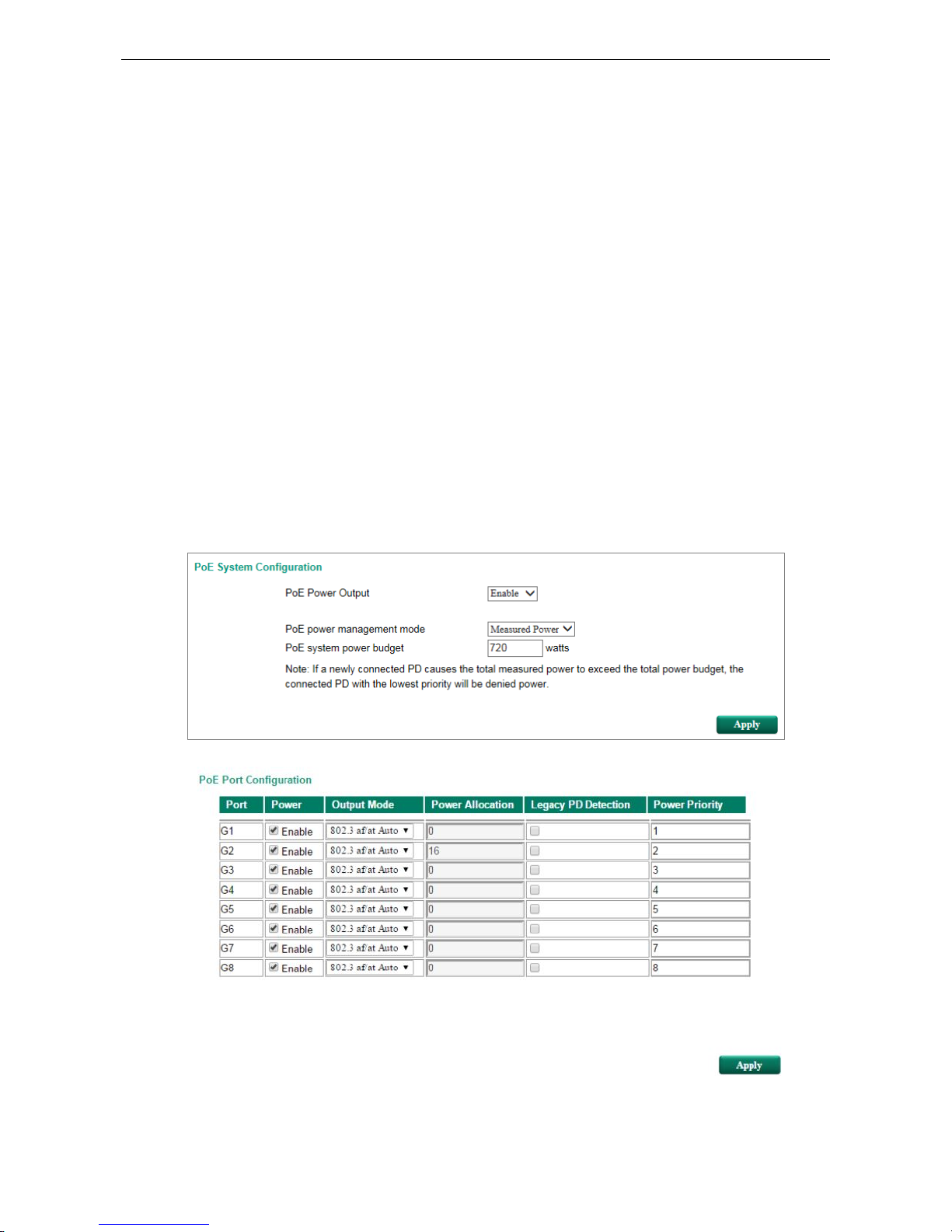
PoE System Configuration
NOTE
The configuration is different, d
epending on whether the “PoE power output managed by” item is set to
“Allocated Power” or “Measured Power.”
PoE Power Management by Allocated Power
PoE Power Management by Measured Power
www.ipc2u.ru
www.moxa.pro
Page 43

PT-G7828/G7728 Featured Functions
3-31
PoE System Configuration Settings
PoE Power Output
Setting Description Factory Default
Enable Enables PoE power transmission to a PD Enable
Disable Disables PoE power transmission to a PD
PoE power management Mode
Setting Description Factory Default
Allocated Power If a powered device is connected that would cause the total
amount of power needed by all connected devices to exceed
the total allocated power limit, the switch will not power up the
device.
Disable
Measured Power If a powered device is connected that would cause the total
amount of power needed by all connected devices to exceed
the total measured
power limit, the switch with will deny power
to the device with the lowest priority.
Enable
Deny next port when exceed
This setting only appears when “PoE power output management mode” is set to “Allocated Power.”
Setting Description Factory Default
wattage Assigns the “Total allocated power” limit for all PoE ports
combined.
720 W
Deny low priority port when exceed
This setting only appears when “PoE power output managed by” is set to “Measured Power.”
Setting Description Factory Default
wattage Assigns the “Total measured power” limit for all PoE ports
combined.
720 W
PoE Port Configuration
Power
Setting Description Factory Default
Checked Allows data and power to be transmitted through the port. Checked
Unchecked Immediately shuts off power to that port
www.ipc2u.ru
www.moxa.pro
Page 44

PT-G7828/G7728 Featured Functions
3-32
Output Mode
Setting Description Factory Default
802.3 af/at Auto Power transmission follows the IEEE 802.3 af/at protocols.
The
acceptable PD resistance range is 17 kΩ to 29 kΩ.
802.3 af/at Auto
High Power Provides a higher power output to the
PD. The acceptable PD
resistance range is 17 kΩ to 29 kΩ, and the power allocation of
the port is automatically set to 36 W.
Force Provides power output to non-802.3 af/at PDs
. The acceptable
PD resistance range is over 2.4 kΩ, and the range of power
allocation is 0 to 36 W.
Power Allocation
Setting Description Factory Default
0 to 36 When the Output Mode is set to Force, the Power Allocation
can be set from 0 to 36 W.
36
Legacy PD Detection
The PoE Ethernet Switch provides a Legacy PD Detection function. When the capacitance of the PD is higher
than 2.7 μF, checking the Legacy PD Detection checkbox enables the system to output power to the PD. In
this case, it will take 10 to 15 seconds for PoE power to be output through this port after the switch is turned
on.
Setting Description Factory Default
Checked
Enables legacy PD detection
Unchecked
Unchecked Disables legacy PD detection
Power Priority
Use Power Priority when managing PoE power with measured power mode. The smaller the number, the
higher the priority. You may set the same priority for different PoE ports, but if you configure two ports with the
same priority, then the port with the lower port number has the higher priority. The setting can range from 1
up to the total number of ports. When the PoE measured power exceeds the assigned limit, the switch will
disable the PoE port with the lowest priority.
Setting Description Factory Default
1 to “number of PoE
ports”
The smaller
the number, the higher the PoE port priority. When
the PoE measured power exceeds the assigned
limit, the switch
will disable the PoE port with the lowest priority.
The PoE port index
number
www.ipc2u.ru
www.moxa.pro
Page 45

PT-G7828/G7728 Featured Functions
3-33
PoE Device Failure Check
The PoE Ethernet switch can monitor the status of a PD via its IP address. If the PD fails, the switch will not
receive a PD response after the defined period, and the authentication process will be restarted. This function
is extremely useful for ensuring your network’s reliability and reducing your management burden.
Enable
Setting Description Factory Default
Checked Enables the PD Failure Check function Unchecked
Unchecked Disables the PD Failure Check function
PoE Device IP Address
Setting Description Factory Default
Max. 15 Characters Enter the PD’s IP address None
No Response Timeout
Setting Description Factory Default
1 to 10 The maximum number of IP checking cycles. 3
Check Period
Setting Description Factory Default
5 to 300
Enter maximum time allowed for each IP checking cycle.
10
No Response Action
Setting Description Factory Default
No Action The PSE has no action on the PD No Action
Reboot PD The PSE reboots the PD after the PD Failure Check
Power Off PD The PSE powers off the PD after the PD Failure Check
www.ipc2u.ru
www.moxa.pro
Page 46

PT-G7828/G7728 Featured Functions
3-34
PoE Timetabling
Powered devices usually do not need to be running 24
hours a day, 7 days a week.
The PoE Ethernet switch
provides a PoE timetabling mechanism t
hat lets users
economize the system
’s power burden by setting a
flexible working schedule for
each PoE port.
Port
Setting Description Factory Default
Port Select which port you would like to configure. The first port of the first
PoE module
Enable
Setting Description Factory Default
Checked Enables the PoE function of the port for the defined time
period.
Unchecked
Unchecked Enables the PoE function of the port all the time.
MON, TUE, WED, THU, FRI, SAT, SUN
Setting Description Factory Default
Checked Select those days on which you would like the port to be
enabled (you will then be able to modify the StartTime and
EndTime)
Disable
Unchecked
The port will not provide PoE power on days that are not check
marked.
Start/End Time
Setting Description Factory Default
Configured time
period
Enter the hour of the day the configuration will be enabled,
and the hour of the day the configuration will be disabled.
0 to 24
PoE Warning Event Settings
Since industrial Ethernet devices are often located at the endpoints of a system, these devices do not always
know what is happening elsewhere on the network. This means that a PoE port connected to a PD must provide
system administrators with real-time alarm messages. Even when control engineers are out of the control room
for an extended period of time, they can still be informed of the status of the PD almost instantaneously when
exceptions occur. The PoE Ethernet switch supports different methods for warning engineers automatically,
including SNMP trap, email, and relay output. It also supports two digital inputs to integrate sensors into your
system to automate alarms using email and relay output. The PoE warning event settings are on the System
Event Settings page.
www.ipc2u.ru
www.moxa.pro
Page 47

PT-G7828/G7728 Featured Functions
3-35
Warning Type
Action Description
Trap A notification will be sent to the trap server when an event is
triggered.
E-Mail A notification will be sent to the email server defined in Email
Settings.
Syslog Record a syslog to a syslog server defined in Syslog Server
Settings.
Relay1/2 Supports digital inputs to integrate sensors. When an event is
triggered, the device will automatically activate an alarm through
the relay output.
Event Type
Port Events Description
PoE PD on Power is being output to the PD.
PoE PD off The PoE power output is cut off.
PoE over current When the current of the port exceeds the following limits:
802.3 af: 350 mA
802.3 at: 600 mA
High Power: 720 mA
Force: 600 mA
PoE PD Failure Check When the switch does not
receive a PD response after the defined
period.
Over Measured Power Limitation When the total PD power consumption exceeds the total measured
power limit.
PoE FETBad When the MOSFET of the port is out of order (
please contact Moxa
for technical service)
PoE over Temperature Check the temperature of the environment. If you cannot keep the
temperature under 75°C, contact Moxa for technical support.
PoE VEE Uvlo - VEE (PoE input voltage)
under Voltage Lockout
The voltage of the power supply has dropped below 44 VDC.
Adjust
the voltage to between 46 and 57 VDC to eliminate this issue.
Over Allocated Power Limitation When the
total PD power consumption exceeds the total allocated
power.
www.ipc2u.ru
www.moxa.pro
Page 48
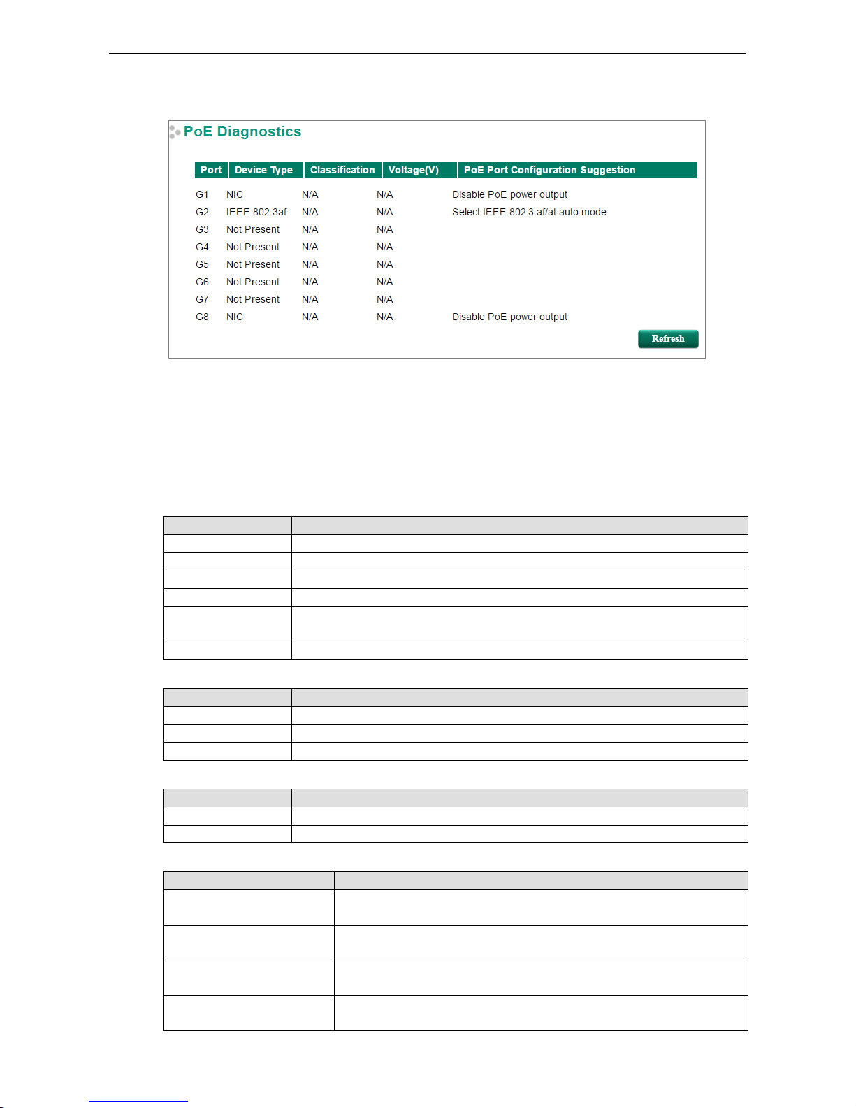
PT-G7828/G7728 Featured Functions
3-36
PoE Diagnose
PoE Diagnose helps users determine the PD conditions. The system provides the user with configuration
options; select the best option for your PDs. Take the following steps to diagnose PD conditions:
Step 1: Check which port numbers will be diagnosed.
Step 2: Click Activate.
Step 3: The system will show the selected PD conditions.
Diagnose Configuration
Device Type
Item Description
Not Present No connection to the port
NIC A NIC is connected to the port
IEEE 802.3af An IEEE 802.3af PD is connected to the port
IEEE 802.3 at An IEEE 802.3at PD is connected to the port
Legacy PoE Device
A legacy PD is connected to the port, and the PD’s detected voltage is too high or low,
or the PD’s detected capacitance is too high.
Unknown Unknown PD connected to the port
Classification
Item Description
N/A The port is not classified
0 to 4 Class 0 to 4
Unknown Unknown class for the port; in this case it will usually be higher than class 4
Voltage (V)
Item Description
N/A No voltage output on the port
Voltage Display the voltage of the port
PoE Port Configuration Suggestion
Item Description
Disable PoE power output When detecting a NIC or unknown PD, the system suggests disabling PoE
power output.
Enable “Legacy PD Detection” When detecting a higher capacitance of PD, the system suggests enabling
Legacy PD Detection.
Select Force Mode When detecting higher/lower resistance or higher capacitance, the system
suggests selecting Force Mode.
Select IEEE 802.3af/at auto
mode
When detecting an IEEE 802.3 af/at PD, the system suggests selecting 802.3
af/at Auto mode.
www.ipc2u.ru
www.moxa.pro
Page 49
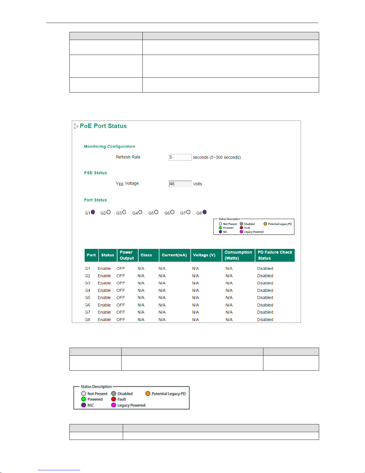
PT-G7828/G7728 Featured Functions
3-37
Item Description
Select high power output When detecting an unknown classification, the system suggests selecting
High Power output.
Raise the external power
supply voltage to greater than
46 VDC
When the external supply voltage is detected at under 46 V, the system
suggests raising the voltage.
Enable PoE function for
detection
The system suggests enabling the PoE function.
PoE Port Status
Monitoring Configuration
Refresh Rate
Setting
Description
Factory Default
5 to 300 The period of time for the system to refresh the PoE Port
Status (in seconds)
5
Port Status
Status Description
Item Description
Not Present
No connection to the port. PoE power is not being provided.
www.ipc2u.ru
www.moxa.pro
Page 50
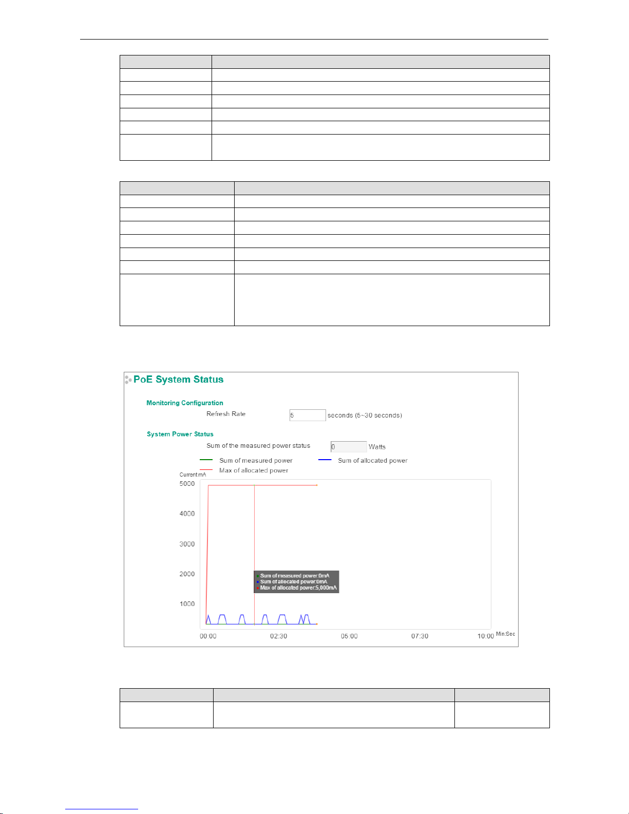
PT-G7828/G7728 Featured Functions
3-38
Item Description
Powered PoE power is being provided by the PSE.
NIC System has detected a NIC connected to the port. PoE power is not being provided.
Disabled The PoE function of the port is disabled. PoE power is not being provided.
Fault In Force mode; the system has detected an out-of-range PD.
Legacy Powered In Force mode; the system has detected a legacy PD.
Potential Legacy PD In 802.3af/at or High Power mode; the system has detected a potential legacy PD.
PoE
power is not being provided.
Port Description
Item Description
Status
Indicates if the PoE function is enabled or disabled.
Power Output Indicates the power output of each PoE port.
Class Indicates the classification of each PoE port.
Current (mA) Indicates the actual current consumed by each PoE port.
Voltage (V) Indicates the actual voltage consumed by each PoE port.
Consumption (Watts) Indicates the actual Power consumed by each PoE port.
PD Failure Check Status Indicates the PD Failure Check status of each PoE port.
Alive: The system receives a response from all pings to the PD.
Not Alive: The system receives no response from pings to the PD.
Disabled: The PD Failure Check function is not activated.
PoE System Status
Monitoring Configuration
Refresh Rate
Setting Description Factory Default
5 to 300 If the Refresh Rate = T, then the PoE Port Status will be
refreshed every T seconds.
5
www.ipc2u.ru
www.moxa.pro
Page 51
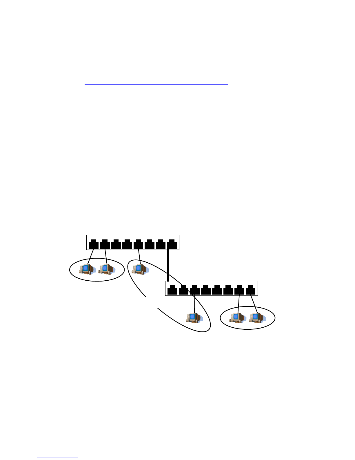
PT-G7828/G7728 Featured Functions
3-39
System Power Status
System Power Status shows a graph of Sum of measured power, Sum of allocated power, and Max of
allocated power. “Sum of measured power” (in green) shows the total measured power of all PDs, “Sum of
allocated power” (in blue) shows the total allocated power, and “Max of allocated power” (in red) shows the
threshold of total PoE power output. The graphs show Current (mA) versus Sec. (second), and are refreshed
at the configured Refresh Rate.
Patent http://www.moxa.com/doc/operations/Moxa_Patent_Marking.pdf
VLAN
Setting up Virtual LANs (VLANs) on your Moxa switch increases the efficiency of your network by dividing the
LAN into logical segments, as opposed to physical segments. In general, VLANs are easier to manage.
The Virtual LAN (VLAN) Concept
What is a VLAN?
A VLAN is a group of devices that can be located anywhere on a network, but which communicate as if they are
on the same physical segment. With VLANs, you can segment your network without being restricted by physical
connections—a limitation of traditional network design. With VLANs you can segment your network into:
• Departmental groups—You could have one VLAN for the marketing department, another for the finance
department, and another for the product development department.
• Hierarchical groups—You could have one VLAN for directors, another for managers, and another for
general staff.
• Usage groups—You could have one VLAN for email users and another for multimedia users.
Benefits of VLANs
The main benefit of VLANs is that they provide a network segmentation system that is far more flexible than
traditional networks. Using VLANs also provides you with three other benefits:
• VLANs ease the relocation of devices on networks: With traditional networks, network administrators
spend much of their time dealing with moves and changes. If users move to a different subnetwork, the
addresses of each host must be updated manually. With a VLAN setup, if a host originally on the Marketing
VLAN, is moved to a port on another part of the network, and retains its original subnet membership, you
only need to specify that the new port is on the Marketing VLAN. You do not need to do any re-cabling.
1 2 3 4 5 6 7 8
1 2 3 4 5 6 7 8
Switch A
Switch B
Department 1
VLAN 1
Department 2
VLAN 2
Department 3
VLAN 3
Backbone connects multiple switches
www.ipc2u.ru
www.moxa.pro
Page 52

PT-G7828/G7728 Featured Functions
3-40
• VLANs provide extra security: Devices within each VLAN can only communicate with other devices on
the same VLAN. If a device on the Marketing VLAN needs to communicate with devices on the Finance VLAN,
the traffic must pass through a routing device or Layer 3 switch.
• VLANs help control traffic: With traditional networks, congestion can be caused by broadcast traffic that
is directed to all network devices, regardless of whether or not they need it. VLANs increase the efficiency
of your network because each VLAN can be set up to contain only those devices that need to communicate
with each other.
VLANs and the Rackmount switch
Your Moxa switch provides support for VLANs using IEEE Std 802.1Q-1998. This standard allows traffic from
multiple VLANs to be carried across one physical link. The IEEE Std 802.1Q-1998 standard allows each port on
your Moxa switch to be placed as follows:
• On a single VLAN defined in the Moxa switch
• On several VLANs simultaneously using 802.1Q tagging
The standard requires that you define the 802.1Q VLAN ID for each VLAN on your Moxa switch before the switch
can use it to forward traffic:
Managing a VLAN
A new or initialized Moxa switch contains a single VLAN—the Default VLAN. This VLAN has the following
definition:
• VLAN Name—Management VLAN
• 802.1Q VLAN ID—1 (if tagging is required)
All the ports are initially placed on this VLAN, and it is the only VLAN that allows you to access the management
software of the Moxa switch over the network.
Communication Between VLANs
If devices connected to a VLAN need to communicate with devices on a different VLAN, a router or Layer 3
switching device with connections to both VLANs needs to be installed. Communication between VLANs can
only take place if they are all connected to a routing or Layer 3 switching device.
VLANs: Tagged and Untagged Membership
The Moxa switch supports 802.1Q VLAN tagging, a system that allows traffic for multiple VLANs to be carried
on a single physical link (backbone, trunk). When setting up VLANs you need to understand when to use
untagged or tagged membership of VLANs. Simply put, if a port is on a single VLAN it can be an untagged
member, but if the port needs to be a member of multiple VLANs, a tagged membership must be defined.
A typical host (e.g., clients) will be an untagged member of one VLAN, defined as an Access Port in a Moxa
switch, while an inter-switch connection will be a tagged member of all VLANs, defined as a Trunk Port in a
Moxa switch.
The IEEE Std 802.1Q-1998 defines how VLANs operate within an open packet-switched network. An 802.1Q
compliant packet carries additional information that allows a switch to determine which VLAN the port belongs
to. If a frame is carrying the additional information, it is known as a tagged frame.
To carry multiple VLANs across a single physical link (backbone, trunk), each packet must be tagged with a
VLAN identifier so that the switches can identify which packets belong in which VLAN. To communicate between
VLANs, a router must be used.
The Moxa switch supports three types of VLAN port settings:
• Access Port: The port connects to a single device that is not tagged. The user must define the default port
PVID that assigns which VLAN the device belongs to. Once the ingress packet of this Access Port egresses
to another Trunk Port (the port needs all packets to carry tag information), the Moxa switch will insert this
PVID into this packet so the next 802.1Q VLAN switch can recognize it.
• Trunk Port: The port connects to a LAN that consists of untagged devices, tagged devices, and/or switches
and hubs. In general, the traffic of the Trunk Port must have a Tag. Users can also assign a PVID to a Trunk
Port. The untagged packet on the Trunk Port will be assigned the default port PVID as its VID.
www.ipc2u.ru
www.moxa.pro
Page 53
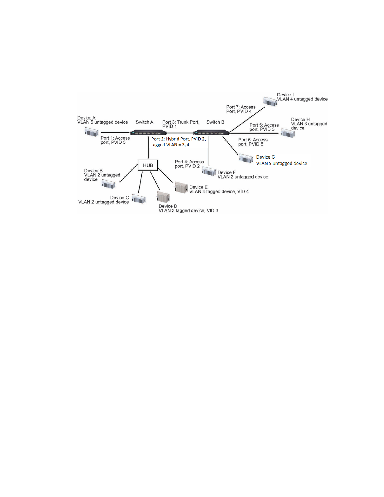
PT-G7828/G7728 Featured Functions
3-41
• Hybrid Port: The port is similar to a Trunk port, except users can explicitly assign tags to be removed from
egress packets.
The following section illustrates how to use these ports to set up different applications.
Sample Applications of VLANs Using Moxa Switches
In this application:
• Port 1 connects a single untagged device and assigns it to VLAN 5; it should be configured as an Access
Port with PVID 5.
• Port 2 connects a LAN with two untagged devices belonging to VLAN 2. One tagged device with VID 3 and
one tagged device with VID 4. It should be configured as a Hybrid Port with PVID 2 for untagged device
and Fixed VLAN (Tagged) with 3 and 4 for tagged device. Since each port can only have one unique PVID,
all untagged devices on the same port must belong to the same VLAN.
• Port 3 connects with another switch. It should be configured as a Trunk Port. GVRP protocol will be used
through the Trunk Port.
• Port 4 connects a single untagged device and assigns it to VLAN 2; it should be configured as an Access
Port with PVID 2.
• Port 5 connects a single untagged device and assigns it to VLAN 3; it should be configured as an Access
Port with PVID 3.
• Port 6 connect a single untagged device and assigns it to VLAN 5; it should be configured as an Access Port
with PVID 5.
• Port 7 connects a single untagged device and assigns it to VLAN 4; it should be configured as an Access
Port with PVID 4.
After the application is properly configured:
• Packets from Device A will travel through Trunk Port 3 with tagged VID 5. Switch B will recognize its VLAN,
pass it to port 6, and then remove tags received successfully by Device G, and vice versa.
• Packets from Devices B and C will travel through Hybrid Port 2 with tagged VID 2. Switch B recognizes its
VLAN, passes it to port 4, and then removes tags received successfully by Device F, and vice versa.
• Packets from Device D will travel through Trunk Port 3 with tagged VID 3. Switch B will recognize its VLAN,
pass to port 5, and then remove tags received successfully by Device H. Packets from Device H will travel
through Trunk Port 3 with PVID 3. Switch A will recognize its VLAN and pass it to port 2, but will not
remove tags received successfully by Device D.
• Packets from Device E will travel through Trunk Port 3 with tagged VID 4. Switch B will recognize its VLAN,
pass it to port 7, and then remove tags received successfully by Device I. Packets from Device I will travel
www.ipc2u.ru
www.moxa.pro
Page 54
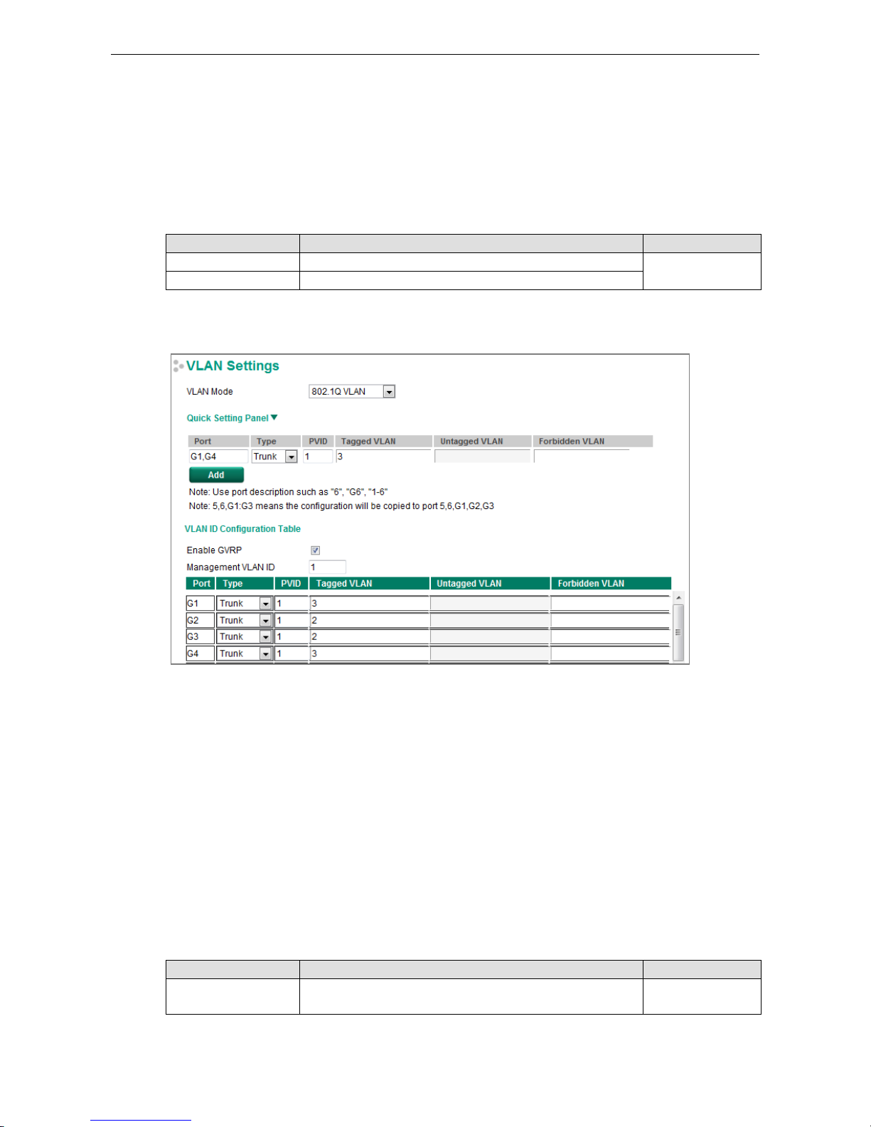
PT-G7828/G7728 Featured Functions
3-42
through Trunk Port 3 with tagged VID 4. Switch A will recognize its VLAN and pass it to port 2, but will not
remove tags received successfully by Device E.
Configuring a Virtual LAN
To configure 802.1Q VLAN and port-based VLANs on the Moxa switch, use the VLAN Settings page to
configure the ports for either an 802.1Q VLAN or Port-based VLAN.
VLAN Mode
Setting Description Factory Default
802.1Q VLAN Sets VLAN mode to 802.1Q VLAN 802.1Q VLAN
Port-based VLAN Sets VLAN mode to Port-based VLAN
VLAN Settings: 802.1Q
When VLAN Mode is set to 802.1Q VLAN, the configuration options will be divided into the Quick Setting Panel
and VLAN ID Configuration Table. The Quick Setting Panel is generally used to configure VLAN settings for
groups of ports, with the settings pushed down to the VLAN ID Configuration Panel when the user clicks the Add
button. The VLAN ID Configuration Table can be used to configure the settings for individual ports.
Quick Setting Panel
Administrators can use the Quick Setting Panel to quickly configure VLAN settings for single ports or groups
of ports. To configure a group of ports, type the port names in the Port column, separated commas (,) for
individual port names, or colons (:) to indicate a range of ports. For example, typing “G1,G3” applies the
settings to ports G1 and G3, whereas typing “G1:G3” applies the settings to ports G1, G2, and G3. Next, if
necessary configure Type, PVID, Tagged VLAN, Untagged VLAN, and Forbidden VLAN, and then click the
Add button to move the settings down to the table at the bottom of the window.
VLAN ID Configuration Table
Enable GVRP
Setting Description Factory Default
Checked/Unchecked Check the checkbox to enable the GVRP function.
Remove the
checkmark to disable the GVRP function.
Checked
www.ipc2u.ru
www.moxa.pro
Page 55
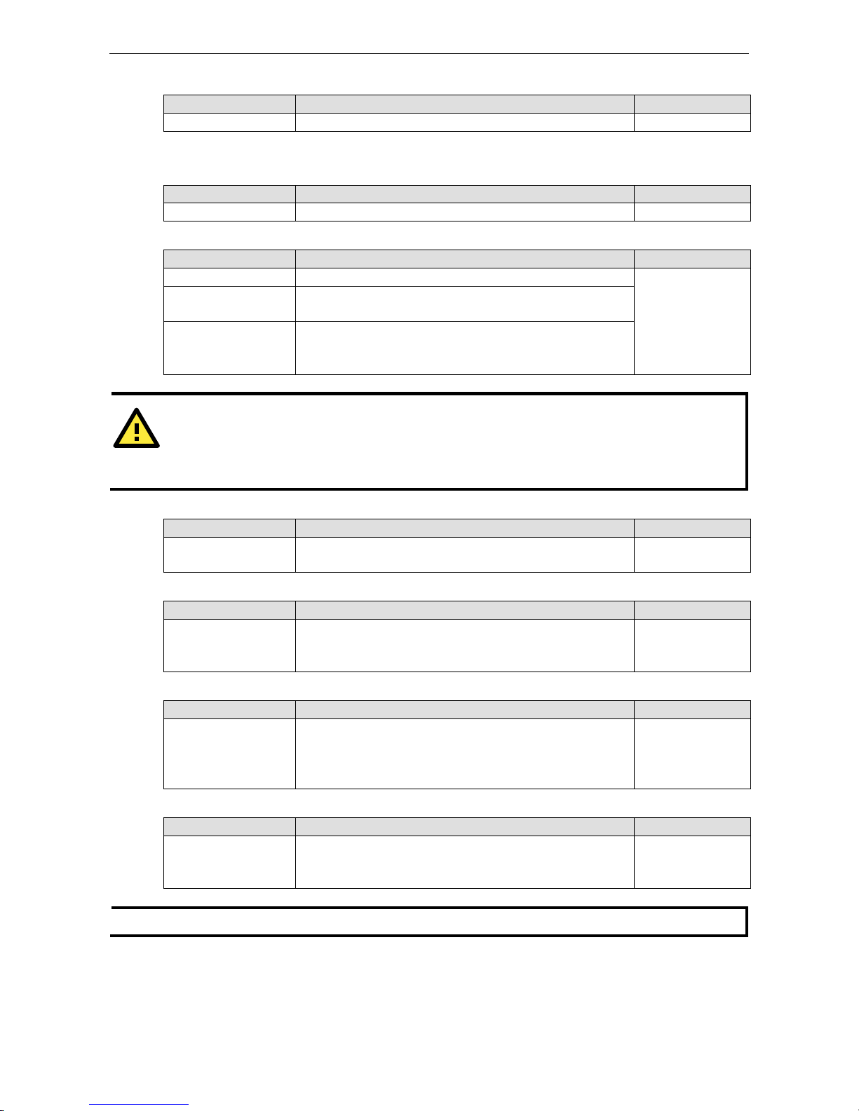
PT-G7828/G7728 Featured Functions
3-43
Management VLAN ID
Setting Description Factory Default
1 to 4094 Assigns the VLAN ID to this Moxa switch. 1
Note: Some of the following settings can be modified in the Quick Setting Panel.
Port
Setting Description Factory Default
Port name Read only N/A
Type
Setting Description Factory Default
Access When this port is connected to a single device, without tags. Access
Trunk When this port is connected to another 802.1Q VLAN aware
switch.
Hybrid When this port is connected to another Access 802.1Q VLAN
aware switch or another LAN that combines tagged and/or
untagged devices and/or other switches/hubs.
ATTENTION
For communication redundancy in the VLAN environment, set
Redundant Port Coupling Ports and
Coupling Control Por
ts to Trunk Port, since these ports act as the backbone for transmitting packets
fr
om different VLANs to different Moxa switch units.
PVID
Setting Description Factory Default
1 to 4094 Sets the default VLAN ID for untagged devices connected
to the
port.
1
Tagged VLAN
Setting Description Factory Default
1 to 4094
This field will be active only when selecting the Trunk or Hybrid
port type. Set the other VLAN ID for tagged devices that
connect to the port. Use commas to separate different VIDs.
None
Untagged VLAN
Setting Description Factory Default
VID range from 1 to
4094
This field is only active when the Hybrid port type is selected.
Set the other VLAN ID for tagged devices that connect to the
port and tags that need to be removed in egress
packets. Use
commas to separate different VIDs.
None
Forbidden VLAN
Setting Description Factory Default
1 to 4094 This field is only active when Trunk or Hybrid port type is
selected
. Set the other VLAN IDs that will not be supported by
this port. Use commas to separate different VIDs.
None
NOTE
The
Quick Setting Panel provides a quick way of configuring multiple VLAN ports with the same setting.
www.ipc2u.ru
www.moxa.pro
Page 56
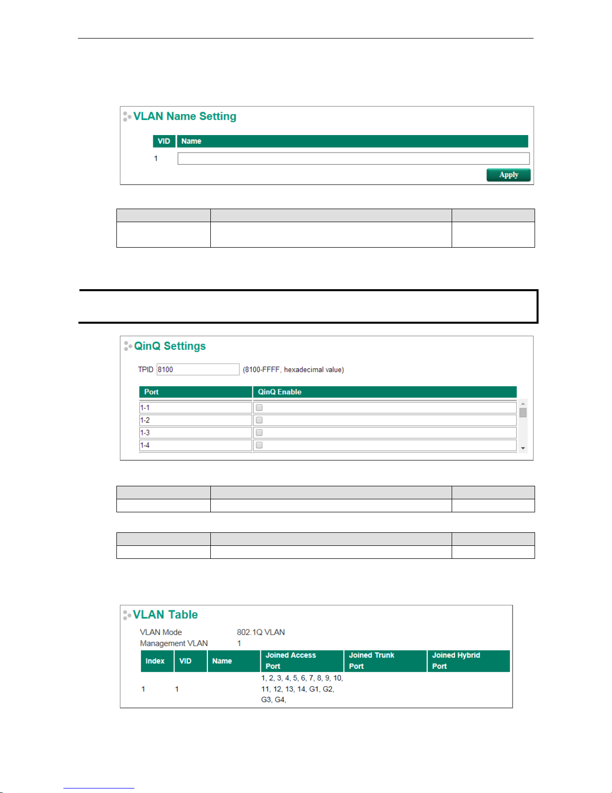
PT-G7828/G7728 Featured Functions
3-44
VLAN Name Setting
For the 802.1Q VLAN, the user is able to set VLAN name of each VLAN ID (VID).
VLAN Name Setting
Setting Description Factory Default
Name The VLAN name can only include these characters,
a-z/A-Z/0-9/-/_/
Null
QinQ Settings
NOTE
Moxa
’s layer 3 switches support the IEEE 802.1ad QinQ function, which allows users to tag double VLAN
headers into a single Ethernet frame.
TPID
Setting Description Factory Default
8100 to FFFF Assign the TPID of the second VLAN tag 8100
QinQ Enable
Setting Description Factory Default
Enable/Disable
Enable VLAN QinQ function
Disable
VLAN Table
www.ipc2u.ru
www.moxa.pro
Page 57
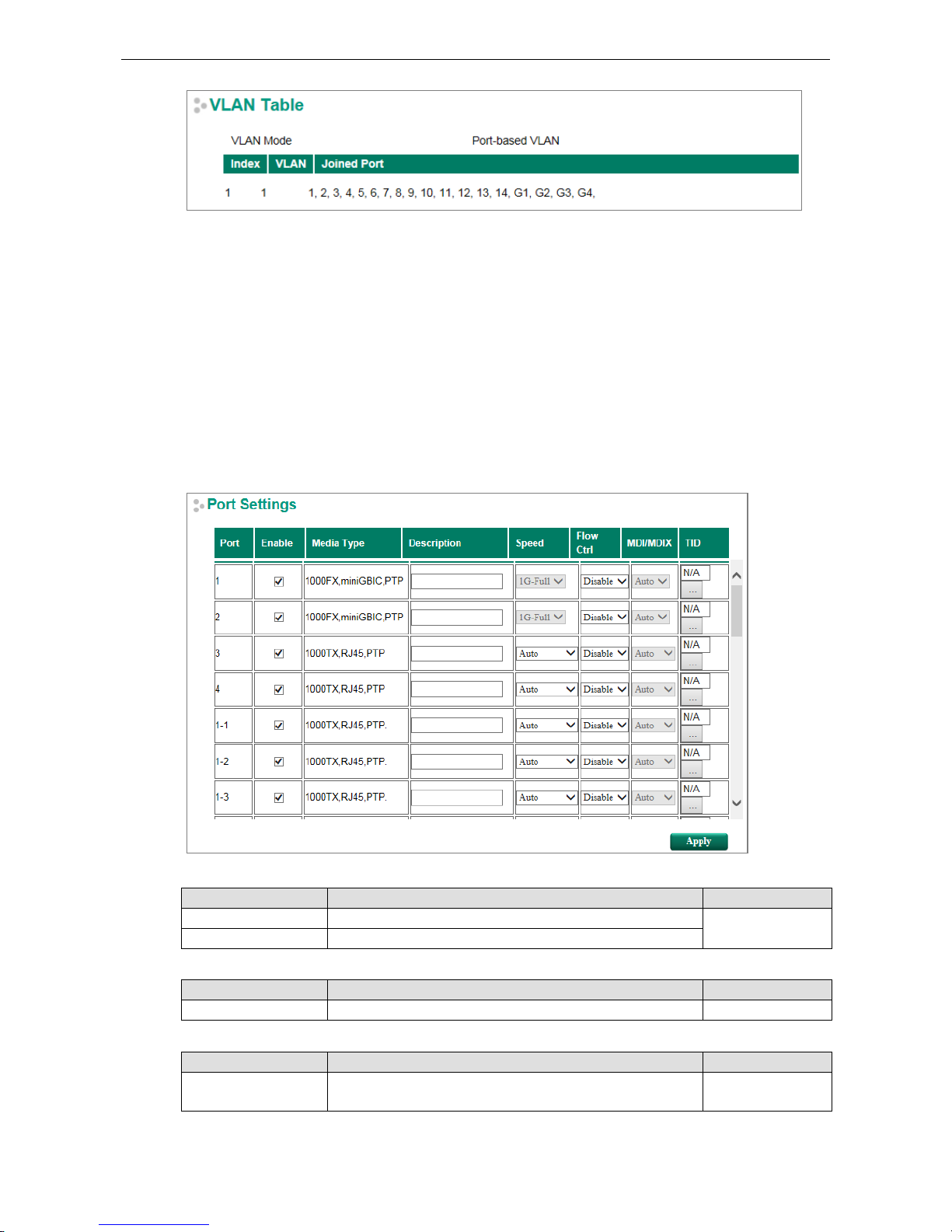
PT-G7828/G7728 Featured Functions
3-45
Use the 802.1Q VLAN table to review the VLAN groups that were created, VLAN Name, Joined Access Ports,
Trunk Ports, and Hybrid Ports, and use the Port-based VLAN table to review the VLAN groups and
Joined Ports.
Port
Port Settings
Port settings are included to give the user control over port access, port transmission speed, flow control, and
port type (MDI or MDIX).
Enable
Setting Description Factory Default
Checked Allows data transmission through the port. Checked
Unchecked Immediately shuts off port access.
Media Type
Setting Description Factory Default
Media type Displays the media type for each module’s port N/A
Description
Setting Description Factory Default
Max. 63 characters Specifies an alias for the port to help administrators
differentiate between different ports. Example: PLC 1
None
www.ipc2u.ru
www.moxa.pro
Page 58

PT-G7828/G7728 Featured Functions
3-46
Speed
Setting Description Factory Default
Auto Allows the port to use the IEEE 802.3u protocol to negotiate
with connected devices. The port and connected devices will
determine the best speed for that connection.
Auto
100M-Full Choose one of these fixed speed options if the connected
Ethernet device has trouble auto-negotiating for line speed.
100M-Half
10M-Full
10M-Half
FDX Flow Ctrl
This setting enables or disables flow control for the port when the port’s Speed is set to Auto. The final result
will be determined by the Auto process between the Moxa switch and connected devices.
Setting Description Factory Default
Enable Enables flow
control for this port when the port’s Speed is set to
Auto.
Disabled
Disable
Disables flow control for this port when the port’s Speed is set
to Auto.
MDI/MDIX
Setting Description Factory Default
Auto Allows the port to auto-detect the port type of the connected
Ethernet device and change the port type accordingly.
Auto
MDI Choose MDI or MDIX if the connected Ethernet device has
trouble auto-negotiating for port type.
MDIX
NOTE
For the Gigabit ports, MDI/MDIX is only Auto mode.
Port Status
The following table shows the status of each port, including the media type, link status, flow control, and port
state.
www.ipc2u.ru
www.moxa.pro
Page 59

PT-G7828/G7728 Featured Functions
3-47
Link Aggregation
Link aggregation involves grouping links into a link aggregation group. A MAC client can treat link aggregation
groups as if they were a single link.
The Moxa switch’s port trunking feature allows devices to communicate by aggregating up to 4 trunk groups,
with a maximum of 8 ports for each group. If one of the 8 ports fails, the other seven ports will automatically
provide backup and share the traffic.
Port trunking can be used to combine up to 8 ports between two Moxa switches. If all ports on both switches
are configured as 100BaseTX and they are operating in full duplex, the potential bandwidth of the connection
will be 1600 Mbps.
The Port Trunking Concept
Moxa has developed a port trunking protocol that provides the following benefits:
• Greater flexibility in setting up your network connections, since the bandwidth of a link can be doubled,
tripled, or quadrupled.
• Redundancy—if one link is broken, the remaining trunked ports share the traffic within this trunk group.
• Load sharing—MAC client traffic can be distributed across multiple links.
To avoid broadcast storms or loops in your network while configuring a trunk, first disable or disconnect all
ports that you want to add to the trunk or remove from the trunk. After you finish configuring the trunk, enable
or re-connect the ports.
If all ports on both switch units are configured as 100BaseTX and they are operating in full duplex mode, the
potential bandwidth of the connection will be up to 1.6 Gbps. This means that users can double, triple, or
quadruple the bandwidth of the connection by port trunking between two Moxa switches.
Each Moxa switch can set a maximum of 3 port trunking groups. When you activate port trunking, certain
settings on each port will be reset to factory default values or disabled:
• Communication redundancy will be reset.
• 802.1Q VLAN will be reset.
• Multicast Filtering will be reset.
• Port Lock will be reset and disabled.
• Set Device IP will be reset.
• Mirror will be reset.
After port trunking has been activated, you can configure these items again for each trunking port.
Port Trunking
The Port Trunking Settings page is where ports are assigned to a trunk group.
www.ipc2u.ru
www.moxa.pro
Page 60

PT-G7828/G7728 Featured Functions
3-48
Step 1:
Select the desired
Trunk Group
Step 2:
Select the
Trunk Type (Static or LACP).
Step 3:
Select the
Trunk Group to modify the desired ports if necessary
Trunk Group (maximum of 4 trunk groups)
Setting Description Factory Default
Trk1, Trk2, Trk3, Trk4
(depends on switching
chip capability; some
Moxa switches only
support 3 trunk
groups)
Specifies the current trunk group. Trk1
The PT-G7728/G8728 supports 4 Trunk Groups
Trunk Type
Setting Description Factory Default
Static Selects Moxa’s static trunking protocol. Static
LACP Selects LACP (IEEE 802.3ad, Link Aggregation Control
Protocol).
Static
Trunking Status
The Trunking Status table shows the Trunk Group configuration status.
www.ipc2u.ru
www.moxa.pro
Page 61

PT-G7828/G7728 Featured Functions
3-49
Link-Swap Fast Recovery
The Link-Swap Fast Recovery function, which is enabled by default, allows the Moxa switch to return to normal
operation extremely quickly after devices are unplugged and then re-plugged into different ports. The recovery
time is on the order of a few milliseconds (compare this with standard commercial switches for which the
recovery time could be on the order of several minutes). To disable the Link-Swap Fast Recovery function, or
to re-enable the function after it has already been disabled, access either the Console utility’s Link-Swap
recovery page, or the Web Browser interface’s Link-Swap fast recovery page, as shown below.
Link-Swap-Fast-Recovery
Setting Description Factory Default
Enable/Disable Select the checkbox to enable the Link-Swap-Fast-Recovery
function
Enable
RSTP Grouping
The purpose of RSTP grouping is to fulfil the legacy requirement of IEDs or PLCs that utilize RSTP to
communicate with each other through the IEC 62439-3 HSR network or Moxa’s proprietary architecture –
Turbo Ring v2. As there is a max hops limitation when using RSTP, the quality of the devices that use RSTP is
also limited. By grouping RSTP devices via assigning “RSTP Group ID”, the total number of RSTP devices that
are connected to Turbo Ring v2 or HSR can be extended.
www.ipc2u.ru
www.moxa.pro
Page 62

PT-G7828/G7728 Featured Functions
3-50
Enable RSTP Grouping
Setting Description Factory Default
Enable/Disable RSTP
Grouping of selected
port
Enable or disable RSTP Grouping of selected port Disable
Group ID
Setting Description Factory Default
1 to 4094 The RSTP Group ID As port number
Connected Network
Setting Description Factory Default
Turbo Ring v2 Ring 1,
Turbo Ring v2 Ring 2,
HSR
Select the connected network of the RSTP Grouping. Turbo Ring v2 Ring 1
NOTE
Moxa’s
PT-G7728/PT-G7828 only supports Turbo Ring v2.
Multicast
Multicast filtering improves the performance of networks that carry multicast traffic. This section explains
multicasts, multicast filtering, and how multicast filtering can be implemented on your Moxa switch.
The Concept of Multicast Filtering
What is an IP Multicast?
A multicast is a packet sent by one host to multiple hosts. Only those hosts that belong to a specific multicast
group will receive the multicast. If the network is set up correctly, a multicast can only be sent to an end-station
or a subset of end-stations on a LAN or VLAN that belong to the multicast group. Multicast group members can
be distributed across multiple subnets, so that multicast transmissions can occur within a campus LAN or over
a WAN. In addition, networks that support IP multicast send only one copy of the desired information across the
www.ipc2u.ru
www.moxa.pro
Page 63

PT-G7828/G7728 Featured Functions
3-51
network until the delivery path that reaches group members diverges. To make more efficient use of network
bandwidth, it is only at these points that multicast packets are duplicated and forwarded. A multicast packet
has a multicast group address in the destination address field of the packet’s IP header.
Benefits of Multicast
The benefits of using IP multicast are:
• It uses the most efficient, sensible method to deliver the same information to many receivers with only one
transmission.
• It reduces the load on the source (for example, a server) since it will not need to produce several copies of
the same data.
• It makes efficient use of network bandwidth and scales well as the number of multicast group members
increases.
• Works with other IP protocols and services, such as Quality of Service (QoS).
Multicast transmission makes more sense and is more efficient than unicast transmission for some applications.
For example, multicasts are often used for video-conferencing, since high volumes of traffic must be sent to
several end-stations at the same time, but where broadcasting the traffic to all end-stations would cause a
substantial reduction in network performance. Furthermore, several industrial automation protocols, such as
Allen-Bradley, EtherNet/IP, Siemens Profibus, and Foundation Fieldbus HSE (High Speed Ethernet), use
multicast. These industrial Ethernet protocols use publisher/subscriber communications models by
multicasting packets that could flood a network with heavy traffic. IGMP Snooping is used to prune multicast
traffic so that it travels only to those end destinations that require the traffic, reducing the amount of traffic on
the Ethernet LAN.
Multicast Filtering
Multicast filtering ensures that only end-stations that have joined certain groups receive multicast traffic. With
multicast filtering, network devices only forward multicast traffic to the ports that are connected to registered
end-stations. The following two figures illustrate how a network behaves without multicast filtering, and with
multicast filtering.
Network without multicast filtering
All hosts receive the multicast
traffic, even if they don’t need it.
www.ipc2u.ru
www.moxa.pro
Page 64
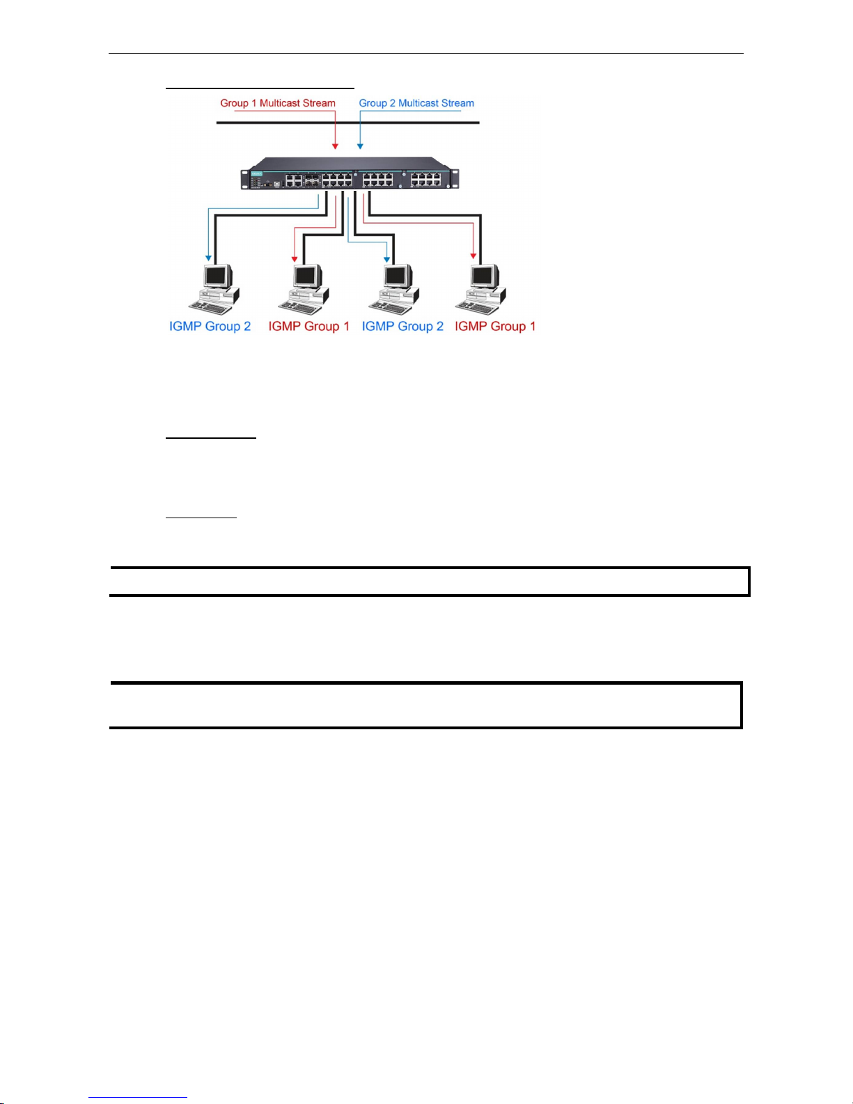
PT-G7828/G7728 Featured Functions
3-52
Network with multicast filtering
Hosts only receive
dedicated
traffic from other hosts belonging
to the same group.
Multicast Filtering and Moxa’s Industrial Rackmount Switches
There are three ways to achieve multicast filtering with a Moxa switch: IGMP (Internet Group Management
Protocol) Snooping, GMRP (GARP Multicast Registration Protocol), and adding a static multicast MAC manually
to filter multicast traffic automatically.
Snooping Mode
Snooping Mode allows your switch to forward multicast packets only to the appropriate ports. The switch
snoops on exchanges between hosts and an IGMP device, such as a router, to find those ports that want to join
a multicast group, and then configures its filters accordingly.
Query Mode
Query mode allows the Moxa switch to work as the Querier if it has the lowest IP address on the subnetwork to
which it belongs.
NOTE
IGMP Snooping Enhanced mode is only provided in Layer 2 switches.
IGMP querying is enabled by default on the Moxa switch to ensure that query election is activated. Enable query
mode to run multicast sessions on a network that does not contain IGMP routers (or queriers). Query mode
allows users to enable IGMP snooping by VLAN ID. Moxa switches support IGMP snooping version 1, version 2,
and version 3. Version 2 is compatible with version 1.The default setting is IGMP V1/V2.
NOTE
Moxa Layer 3 switches are compatible with any device that conforms to the IGMP v2 and IGMP v3 device
protocols. Layer 2 switches only support IGMP v1/v2.
IGMP Multicast Filtering
IGMP is used by IP-supporting network devices to register hosts with multicast groups. It can be used on all
LANs and VLANs that contain a multicast capable IP router, and on other network devices that support
multicast filtering. Moxa switches support IGMP version 1, 2 and 3. IGMP version 1 and 2 work as follows:
• The IP router (or querier) periodically sends query packets to all end-stations on the LANs or VLANs that are
connected to it. For networks with more than one IP router, the router with the lowest IP address is the
querier. A switch with IP address lower than the IP address of any other IGMP queriers connected to the LAN
or VLAN can become the IGMP querier.
• When an IP host receives a query packet, it sends a report packet back that identifies the multicast group
that the end-station would like to join.
• When the report packet arrives at a port on a switch with IGMP Snooping enabled, the switch knows that the
port should forward traffic for the multicast group, and then proceeds to forward the packet to the router.
• When the router receives the report packet, it registers that the LAN or VLAN requires traffic for the
multicast groups.
• When the router forwards traffic for the multicast group to the LAN or VLAN, the switches only forward the
traffic to ports that received a report packet.
www.ipc2u.ru
www.moxa.pro
Page 65

PT-G7828/G7728 Featured Functions
3-53
IGMP version 3 supports “source filtering,” which allows the system to define how to treat packets from
specified source addresses. The system can either white-list or black-list specified sources.
IGMP version comparison
IGMP Version Main Features Reference
V1 Periodic query RFC-1112
V2 Compatible with V1 and adds:
a. Group-specific query
b. Leave group messages
c. Resends specific queries to verify leave message was the last one in
the group
d. Querier election
RFC-2236
V3 Compatible with V1, V2, and adds:
Source filtering
- accept multicast traffic from specified source
- accept multicast traffic from any source except the specified source
RFC-3376
GMRP (GARP Multicast Registration Protocol)
Moxa switches support IEEE 802.1D-1998 GMRP (GARP Multicast Registration Protocol), which is different from
IGMP (Internet Group Management Protocol). GMRP is a MAC-based multicast management protocol, whereas
IGMP is IP-based. GMRP provides a mechanism that allows bridges and end stations to register or de-register
Group membership information dynamically. GMRP functions similarly to GVRP, except that GMRP registers
multicast addresses on ports. When a port receives a GMRP-join message, it will register the multicast
address to its database if the multicast address is not registered, and all the multicast packets with that
multicast address are able to be forwarded from this port. When a port receives a GMRP-leave message, it will
de-register the multicast address from its database, and all the multicast packets with this multicast address
will not be able to be forwarded from this port.
Static Multicast MAC
Some devices may only support multicast packets, but not support either IGMP Snooping or GMRP. The Moxa
switch supports adding multicast groups manually to enable multicast filtering.
Enabling Multicast Filtering
Use the USB console or web interface to enable or disable IGMP Snooping and IGMP querying. If IGMP Snooping
is not enabled, then IP multicast traffic is always forwarded, flooding the network.
IGMP Snooping
IGMP Snooping provides the ability to prune multicast traffic so that it travels only to those end destinations
that require that traffic, thereby reducing the amount of traffic on the Ethernet LAN.
NOTE
IGMP Snooping will be disabled when Port
-Based VLAN is enabed.
www.ipc2u.ru
www.moxa.pro
Page 66
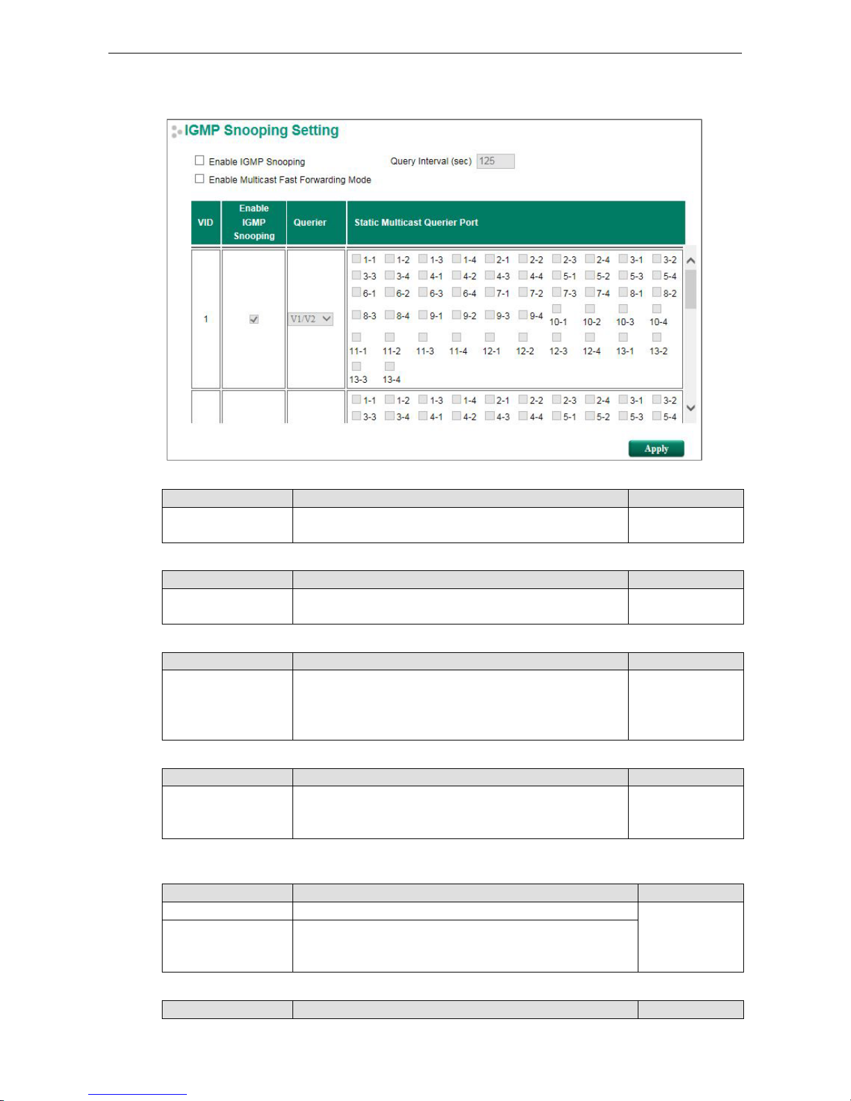
PT-G7828/G7728 Featured Functions
3-54
IGMP Snooping Setting
Enable IGMP Snooping (Global)
Setting Description Factory Default
Enable/Disable Select
the Enable IGMP Snooping checkbox near the top of the
window to enable the IGMP Snooping function globally.
Disabled
Query Interval (sec)
Setting Description Factory Default
Numerical value, input
by the user
Sets the query interval of the Querier function globally. Valid
settings are from 20 to 600 seconds.
125 seconds
Enable Multicast Fast Forwarding Mode
Setting Description Factory Default
Enable/Disable Select the Enable Multicast Fast Forwarding Mode checkbox
to
achieve fast multicast forwarding path re-learning while the
ring redundant network is down.
Note: Turbo Ring V2 or Turbo Chain must be enabled.
Disabled
Enable IGMP Snooping
Setting Description Factory Default
Enable/Disable Enables or disables the IGMP Snooping function on that
particular VLAN.
Enabled if IGMP
Snooping is enabled
globally
Querier
Setting Description Factory Default
Disable Disables the Moxa switch’s querier function. V1/V2
V1/V2 and V3 checkbox V1/V2: Enables the
switch to send IGMP snooping version 1 and
2 queries
V3: Enables the switch to send IGMP snooping version 3 queries
Static Multicast Querier Port
Setting Description Factory Default
www.ipc2u.ru
www.moxa.pro
Page 67
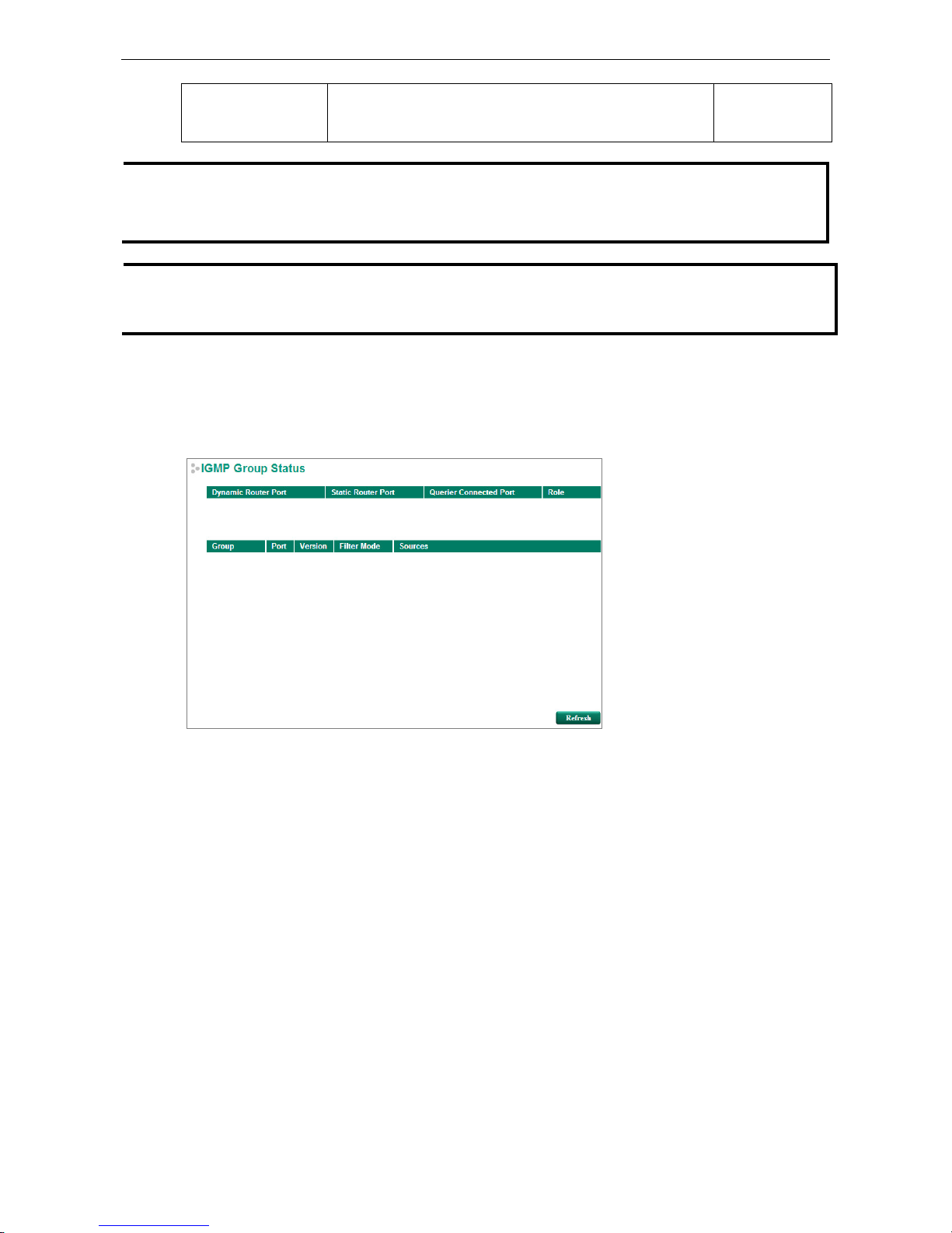
PT-G7828/G7728 Featured Functions
3-55
Select/Deselect Select the
ports that will connect to the multicast routers. These
ports will receive all multicast packets from the source. This
option is only active when IGMP Snooping is enabled.
Disabled
NOTE
If a router or layer 3 switch
is connected to the network, it will act as the Querier, and consequently this
Querier option will be disabled on all Moxa layer 2 switches.
If all switches on the network are Moxa layer 2 switches, then only one layer 2 switch will act as Querier.
NOTE Multicast Fast Forwarding Mode is one function of V
-ON technology that
should be enabled in layer 2 and layer
3 switches. For
a detailed introduction, refer to
Moxa Managed Ethernet Switch Redundancy Protocol (UI 2.0)
User’s Manual
.
IGMP Group Status
The Moxa switch displays the current active IGMP groups that were detected. On this page, you can view IGMP
group settings by VLAN ID.
The information shown in the table includes:
• Dynamic Router Port: Indicates that a multicast router connects to or sends packets from these port(s).
• Static Router Port: Displays the static multicast querier port(s).
• Querier Connected Port: Displays the port that is connected to the querier.
• Role: Indicates if the switch is a querier. Displays Querier or Non-Querier.
• Group: Displays the multicast group addresses.
• Port: Displays the port that receives the multicast stream or the port the multicast stream is forwarded to
• Version: Displays the IGMP Snooping version.
• Filter Mode: Indicates that the multicast source address is included or excluded. Displays Include or Exclude
when IGMP v3 is enabled
• Sources: Displays the multicast source address when IGMP v3 is enabled
Stream Table
This page displays the multicast stream forwarding status. It allows you to view the status by VLAN ID.
www.ipc2u.ru
www.moxa.pro
Page 68
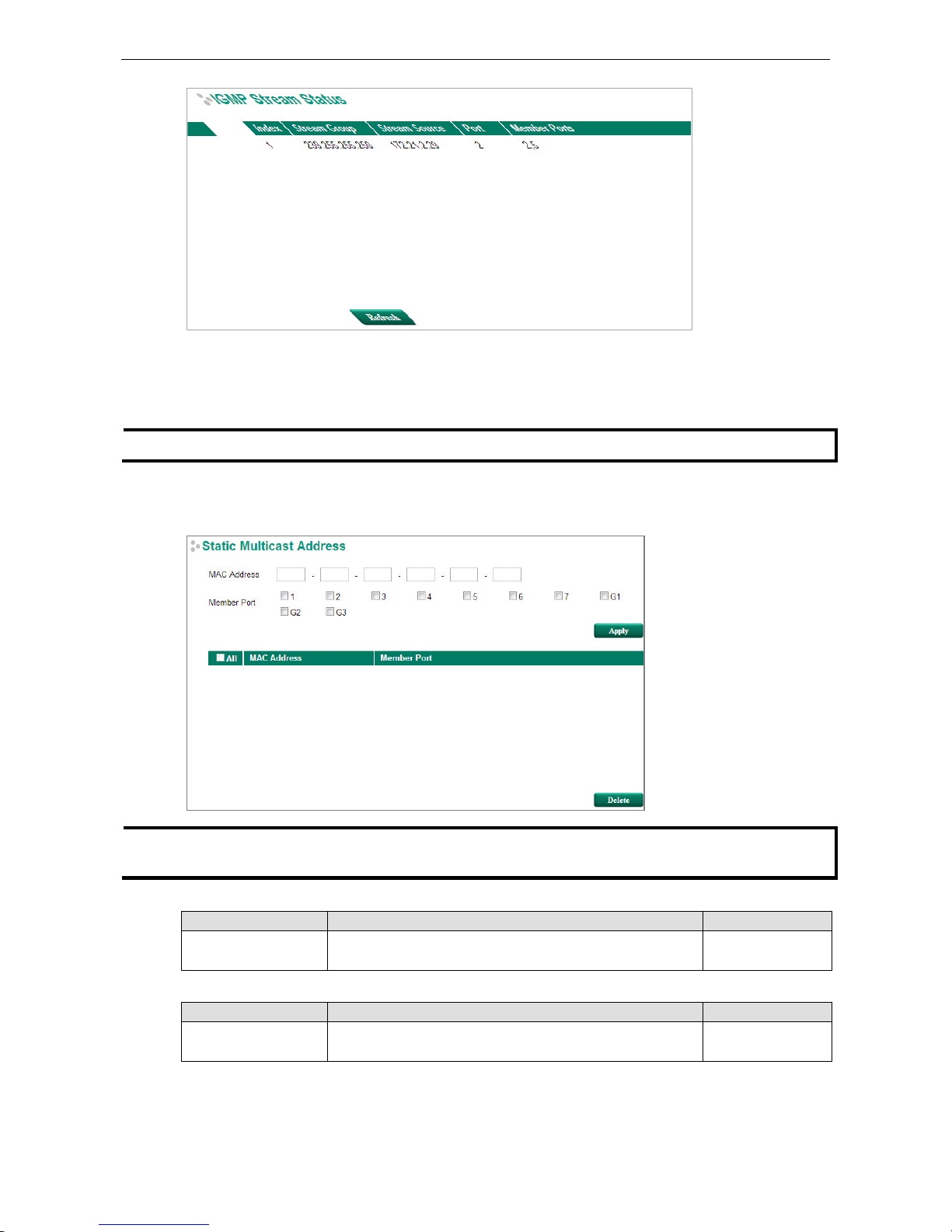
PT-G7828/G7728 Featured Functions
3-56
Stream Group: Multicast group IP address
Stream Source: Multicast source IP address
Port: The port that receives the multicast stream
Member Ports: Ports the multicast stream is forwarded to
NOTE
IGMP Stream Status is only
supported by Moxa’s Layer 3 switches.
Static Multicast Address
NOTE
The MAC address (
01:00:5E:XX:XX:XX) will appear on the Static Multicast Address page. Activate IGMP
Snooping to implement automatic classification
.
MAC Address
Setting Description Factory Default
Integer Type the MAC address in the MAC Address field to specify a
static multicast address.
None
Member Port
Setting Description Factory Default
Select/Deselect Select the appropriate checkboxes to define the join ports for
this multicast group.
None
www.ipc2u.ru
www.moxa.pro
Page 69
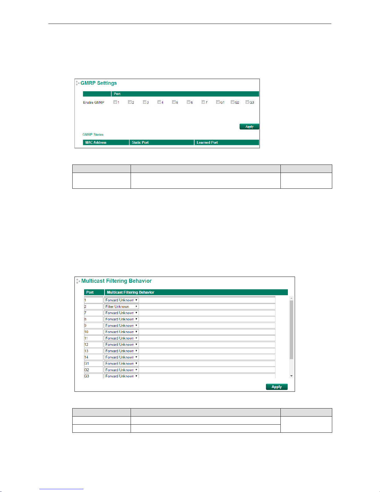
PT-G7828/G7728 Featured Functions
3-57
GMRP
GMRP is a MAC-based multicast management protocol, whereas IGMP is IP-based. GMRP provides a
mechanism that allows bridges and end stations to register or un-register Group membership information
dynamically.
Enable GMRP
Setting Description Factory Default
Select/Deselect Select the appropriate checkboxes to define which ports
are to
be GMRP enabled.
None
GMRP Status
The Moxa switch displays the current active GMRP groups that were detected.
MAC Address: The Multicast MAC address
Static Port: This multicast address is defined by static multicast
Learned Port: This multicast address is learned by GMRP
Multicast Filtering Behavior
Multicast Filtering Behavior supports two options: Forward Unknown and Filter Unknown.
Multicast Filtering Behavior
Setting Description Factory Default
Forward Unknown Allows the switch to forward all unknown Multicast streams Forward Unknown
Filter Unknown Allows the switch to drop all unknown Multicast steams
www.ipc2u.ru
www.moxa.pro
Page 70

PT-G7828/G7728 Featured Functions
3-58
QoS
The Moxa switch’s traffic prioritization capability provides Quality of Service (QoS) to your network by making
data delivery more reliable. You can prioritize traffic on your network to ensure that high priority data is
transmitted with minimum delay. Traffic can be controlled by a set of rules to obtain the required Quality of
Service for your network. The rules define different types of traffic and specify how each type should be treated
as it passes through the switch. The Moxa switch can inspect both IEEE 802.1p/1Q layer 2 CoS tags, and even
layer 3 TOS information to provide consistent classification of the entire network. The Moxa switch’s QoS
capability improves the performance and determinism of industrial networks for mission-critical applications.
The Traffic Prioritization Concept
Traffic prioritization allows you to prioritize data so that time-sensitive and system-critical data can be
transferred smoothly and with minimal delay over a network. The benefits of using traffic prioritization are:
• Improve network performance by controlling a wide variety of traffic and by managing congestion.
• Assign priorities to different categories of traffic. For example, set higher priorities for time-critical or
business-critical applications.
• Provide predictable throughput for multimedia applications, such as video conferencing or voice over IP,
and minimize traffic delay and jitter.
• Improve network performance as the amount of traffic grows. Doing so will reduce costs since it will not be
necessary to keep adding bandwidth to the network.
Traffic prioritization uses the four traffic queues that are present in your Moxa switch to ensure that high
priority traffic is forwarded on a different queue from lower priority traffic. Traffic prioritization provides Quality
of Service (QoS) to your network.
Moxa switch traffic prioritization depends on two industry-standard methods:
• IEEE 802.1D—a layer 2 marking scheme.
• Differentiated Services (DiffServ)—a layer 3 marking scheme.
IEEE 802.1D Traffic Marking
The IEEE Std 802.1D, 1998 Edition marking scheme, which is an enhancement to IEEE Std 802.1D, enables
Quality of Service on the LAN. Traffic service levels are defined in the IEEE 802.1Q 4-byte tag, which is used to
carry VLAN identification as well as IEEE 802.1p priority information. The 4-byte tag immediately follows the
destination MAC address and Source MAC address.
The IEEE Std 802.1D, 1998 Edition priority marking scheme assigns an IEEE 802.1p priority level between 0
and 7 to each frame. The priority marking scheme determines the level of service that this type of traffic should
receive. Refer to the table below for an example of how different traffic types can be mapped to the eight IEEE
802.1p priority levels.
IEEE 802.1p Priority Level IEEE 802.1D Traffic Type
0 Best Effort (default)
1 Background
2 Standard (spare)
3 Excellent Effort (business critical)
4 Controlled Load (streaming multimedia)
5 Video (interactive media); less than 100 milliseconds of latency and jitter
6 Voice (interactive voice); less than 10 milliseconds of latency and jitter
7 Network Control Reserved traffic
Even though the IEEE 802.1D standard is the most widely used prioritization scheme for LAN environments, it
still has some restrictions:
www.ipc2u.ru
www.moxa.pro
Page 71

PT-G7828/G7728 Featured Functions
3-59
• It requires an additional 4-byte tag in the frame, which is normally optional for Ethernet networks. Without
this tag, the scheme cannot work.
• The tag is part of the IEEE 802.1Q header, so to implement QoS at layer 2, the entire network must
implement IEEE 802.1Q VLAN tagging.
• It is only supported on a LAN and not across routed WAN links, since the IEEE 802.1Q tags are removed
when the packets pass through a router.
Differentiated Services (DiffServ) Traffic Marking
DiffServ is a Layer 3 marking scheme that uses the DiffServ Code Point (DSCP) field in the IP header to store
the packet priority information. DSCP is an advanced intelligent method of traffic marking that allows you to
choose how your network prioritizes different types of traffic. DSCP uses 64 values that map to user-defined
service levels, allowing you to establish more control over network traffic.
The advantages of DiffServ over IEEE 802.1D are:
• You can configure how you want your switch to treat selected applications and types of traffic by assigning
various grades of network service to them.
• No extra tags are required in the packet.
• DSCP uses the IP header of a packet to preserve priority across the Internet.
• DSCP is backwards compatible with IPV4 TOS, which allows operation with existing devices that use a layer
3 TOS enabled prioritization scheme.
Traffic Prioritization
Moxa switches classify traffic based on layer 2 of the OSI 7 layer model, and the switch prioritizes received
traffic according to the priority information defined in the received packet. Incoming traffic is classified based
upon the IEEE 802.1D frame and is assigned to the appropriate priority queue based on the IEEE 802.1p service
level value defined in that packet. Service level markings (values) are defined in the IEEE 802.1Q 4-byte tag,
and consequently traffic will only contain 802.1p priority markings if the network is configured with VLANs and
VLAN tagging. The traffic flow through the switch is as follows:
• A packet received by the Moxa switch may or may not have an 802.1p tag associated with it. If it does not,
then it is given a default 802.1p tag (which is usually 0). Alternatively, the packet may be marked with a
new 802.1p value, which will result in all knowledge of the old 802.1p tag being lost.
• Because the 802.1p priority levels are fixed to the traffic queues, the packet will be placed in the
appropriate priority queue, ready for transmission through the appropriate egress port. When the packet
reaches the head of its queue and is about to be transmitted, the device determines whether or not the
egress port is tagged for that VLAN. If it is, then the new 802.1p tag is used in the extended 802.1D header.
• The Moxa switch will check a packet received at the ingress port for IEEE 802.1D traffic classification, and
then prioritize it based on the IEEE 802.1p value (service levels) in that tag. It is this 802.1p value that
determines which traffic queue the packet is mapped to.
Traffic Queues
The hardware of Moxa switches has multiple traffic queues that allow packet prioritization to occur. Higher
priority traffic can pass through the Moxa switch without being delayed by lower priority traffic. As each packet
arrives in the Moxa switch, it passes through any ingress processing (which includes classification,
marking/re-marking), and is then sorted into the appropriate queue. The switch then forwards packets from
each queue.
Moxa switches support two different queuing mechanisms:
• Weight Fair: This method services all the traffic queues, giving priority to the higher priority queues.
Under most circumstances, the Weight Fair method gives high priority precedence over low priority, but in
the event that high priority traffic does not reach the link capacity, lower priority traffic is not blocked.
• Strict: This method services high traffic queues first; low priority queues are delayed until no more high
priority data needs to be sent. The Strict method always gives precedence to high priority over low priority.
www.ipc2u.ru
www.moxa.pro
Page 72
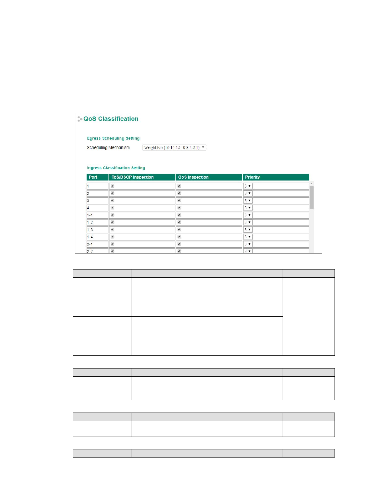
PT-G7828/G7728 Featured Functions
3-60
Configuring Traffic Prioritization
Quality of Service (QoS) provides a traffic prioritization capability to ensure that important data is delivered
consistently and predictably. The Moxa switch can inspect IEEE 802.1p/1Q layer 2 CoS tags, and even layer 3
TOS information, to provide a consistent classification of the entire network. The Moxa switch’s QoS capability
improves your industrial network’s performance and determinism for mission critical applications.
CoS Classification
Scheduling Mechanism
Setting Description Factory Default
Weight Fair The Moxa switch has 8 priority queues. In the weight fair
scheme, an 16, 14, 12, 10, 8, 4, 2, 1
weighting is applied to the
four priorities. This approach prevents the lower priority frames
from being starved of opportunity for transmission wit
h only a
slight delay to the higher priority frames
Weight Fair
Strict In the Strict-priority scheme, all top-priority frames egress a
port until that priority’s frames egress. This approach can cause
the lower priorities to be starved of opportunity for
transmitting
frames but ensures that all high priority frames will egress the
switch as soon as possible.
TOS/DSCP Inspection
Setting Description Factory Default
Enable/Disable Enables or disables the Moxa switch for inspecting Type of
Server (TOS) bits
in the IPV4 frame to determine the priority of
each frame.
Enable
COS Inspection
Setting
Description
Factory Default
Enable/Disable
Enables or disables the Moxa switch for inspecting 802.1p COS
tags in the MAC frame to determine the priority of each frame.
Enable
Priority
Setting Description Factory Default
www.ipc2u.ru
www.moxa.pro
Page 73
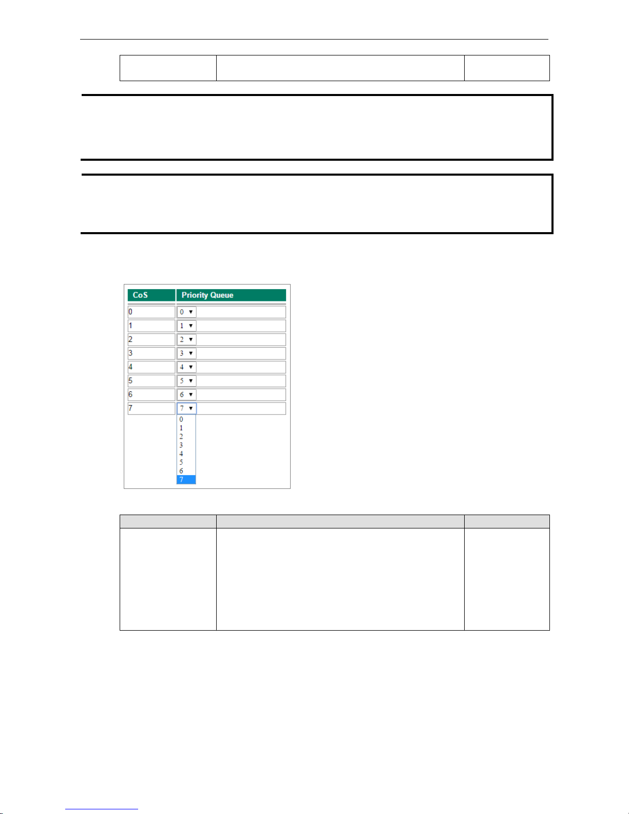
PT-G7828/G7728 Featured Functions
3-61
0 to 7 The port priority has 8 priority queues: from 0 (lowest) to 7
(highest)
3
NOTE
The priority of an ingress frame is determined in the following order:
1. ToS/DSCP Inspection
2. CoS Inspection
3. Priority
NOTE
The designer can enable these classifications individually or in combination. For instance, if a “hot” higher
priority port is required for a network design,
TOS/DSCP Inspection and Cos Inspection
can be disabled.
This setting leaves only port default priority active, which results in all ingress frames being assigned the same
priority on that port.
Priority Mapping
CoS Value and Priority Queues
Setting Description Factory Default
0 to 7 Maps different CoS values to 8 different egress queues. CoS 0: 0
CoS 1: 1
CoS 2: 2
CoS 3: 3
CoS 4: 4
CoS 5: 5
CoS 6: 6
CoS 7: 7
www.ipc2u.ru
www.moxa.pro
Page 74

PT-G7828/G7728 Featured Functions
3-62
DSCP Mapping
DSCP Value and Priority
Setting Description Factory Default
0 to 7
Different DSCP values map to one of 8 different priorities.
0
8 to 15 1
16 to 23 2
24 to 31 3
32 to 39 4
40 to 47 5
48 to 55 6
56 to 63 7
Rate Limiting
In general, one host should not be allowed to occupy unlimited bandwidth, particularly when the device
malfunctions. For example, so-called “broadcast storms” could be caused by an incorrectly configured topology,
or a malfunctioning device. Moxa industrial Ethernet switches not only prevent broadcast storms, but can also
be configured to a different ingress rate for all packets, giving administrators full control of their limited
bandwidth to prevent undesirable effects caused by unpredictable faults.
The Control Mode setting on the Rate Limiting page can be set to Normal or Port Disable.
Control Mode
Setting Description Factory Default
Normal Set the max. ingress rate limit for different packet types 30 seconds
Port Disable When the ingress multicast and broadcast packets exceed the
ingress rate limit, the port will be disabled for a certain period.
During this period, all packets from this port will be discarded.
Unlimited
www.ipc2u.ru
www.moxa.pro
Page 75

PT-G7828/G7728 Featured Functions
3-63
Rate Limiting: Normal
Ingress Rate Limit
Policy Description Factory Default
Limit All
Select the ingress rate limit for different packet types from the
following options: Unlimited, 128K, 256K, 512K, 1M, 2M, 4M,
8M, 10%(100Mbps), 15%(150Mbps), 25%(250Mbps),
35%(350Mbps), 50%(500Mbps), 65%(650Mbps),
85%(850Mbps)
Limit Broadcast 8M
Limit Broadcast,
Multicast, Flooded
Unicast
Limit Broadcast,
Multicast
Limit Broadcast
Egress Rate Limit
Setting Description Factory Default
Egress rate Select the egress rate limit (% of max. throughput) for all
packets from the following options: Not Limited, 3%, 5%, 10%,
15%, 25%, 35%, 50%, 65%, 85%
Unlimited
www.ipc2u.ru
www.moxa.pro
Page 76

PT-G7828/G7728 Featured Functions
3-64
Rate Limiting: Port Disable
Setting Description Factory Default
Port disable duration
(1-65535 seconds)
When the ingress packets exceed the ingress rate limit, the
port will be disabled for a certain period.
30 seconds
Ingress (frames per
second)
Select the ingress rate (fps) limit for all packets from the
following options: Not Limited, 44640, 74410, 148810,
223220, 372030, 520840, 744050
Unlimited
Security
Security can be categorized into two levels: the user name/password level, and the port access level. Moxa
switches provide many kinds of security functions, including Management Interface, Trusted Access, SSL/SSH
Authentication certificate, Login Authentication, IEEE 802.1X, MAC Authentication Bypass, Port Security,
Broadcast Storm Protection, Loop Protection, and Access Control List.
Management Interface
www.ipc2u.ru
www.moxa.pro
Page 77

PT-G7828/G7728 Featured Functions
3-65
Enable HTTP
Setting Description Factory Default
Select/Deselect Select the appropriate checkboxes to enable HTTP. TCP Port: 80
Enable HTTPS
Setting Description Factory Default
Select/Deselect Select the appropriate checkboxes to enable HTTPS. TCP Port: 443
Enable Telnet
Setting Description Factory Default
Select/Deselect Select the appropriate checkboxes to enable Telnet. TCP Port: 23
Enable SSH
Setting
Description
Factory Default
Select/Deselect Select the appropriate checkboxes to enable SSH. TCP Port: 22
Enable SNMP
Setting Description Factory Default
Select/Deselect Select the appropriate checkboxes to enable SNMP. TCP Port: 161
Enable Moxa Service
Setting Description Factory Default
Select/Deselect Select the appropriate checkboxes to enable Moxa Service.
NOTE: Moxa Service is only for Moxa network management
software suite.
TCP Port: 4000
UDP Port: 4000
Enable Moxa Service (Encrypted)
Setting Description Factory Default
Select/Deselect Select the appropriate checkboxes to enable Moxa Service
(Encrypted). NOTE: Moxa Service (Encrypted) is only for
Moxa
network management software suite.
TCP Port: 443
UDP Port: 40404
Maximum Login Users for HTTP+HTTPS
Setting Description Factory Default
Integer (1 to 10) Sets the maximum number of login users for HTTP and HTTPS 5
Maximum Login Users for Telnet+SSH
Setting Description Factory Default
Integer (1 to 5)
Sets the maximum number of login users for Telnet and SSH
1
Auto Logout Setting (min)
Setting Description Factory Default
Integer (0 to 1440) Sets the web auto logout period.
(Enter 0 to disable this function.)
5
www.ipc2u.ru
www.moxa.pro
Page 78

PT-G7828/G7728 Featured Functions
3-66
Trusted Access
The Moxa switch uses an IP address-based filtering method to control access.
You may add or remove IP addresses to limit access to the Moxa switch. When the Trusted Access list is enabled,
only addresses on the list will be allowed access to the Moxa switch. Each IP address and netmask entry can be
tailored for different situations:
• Grant access to one host with a specific IP address
For example, enter IP address 192.168.1.1 with netmask 255.255.255.255 to allow access to 192.168.1.1
only.
• Grant access to any host on a specific subnetwork
For example, enter IP address 192.168.1.0 with netmask 255.255.255.0 to allow access to all IPs on the
subnet defined by this IP address/subnet mask combination.
• Grant access to all hosts
Make sure the Trusted Access list is not enabled by removing the checkmark from Enable trusted access.
The following table shows additional configuration examples:
Hosts That Need Access Input Format
Any host Disable
192.168.1.120 192.168.1.120 / 255.255.255.255
192.168.1.1 to 192.168.1.254 192.168.1.0 / 255.255.255.0
192.168.0.1 to 192.168.255.254 192.168.0.0 / 255.255.0.0
192.168.1.1 to 192.168.1.126 192.168.1.0 / 255.255.255.128
192.168.1.129 to 192.168.1.254 192.168.1.128 / 255.255.255.128
www.ipc2u.ru
www.moxa.pro
Page 79

PT-G7828/G7728 Featured Functions
3-67
SSL Certificate Management
Certificate Import
1. Click Browse and select Public-Key Cryptography Standard (PKCS) #12 certificate file
2. Enter the Import Password and click Import
3. The SSL certificate is updated
Regenerate SSL Certificate
Setting Description Factory Default
Select/Deselect Enable the SSL Certificate Regeneration Deselect
SSH Key Management
SSH Key Re-generate
Setting Description Factory Default
Select/Deselect Enable SSH Key Re-generate Deselect
Authentication
Login Authentication
Moxa switches provide three different user login authentications: TACACS+ (Terminal Access Controller
Access-Control System Plus), RADIUS (Remote Authentication Dial In User Service), and Local. The TACACS+
and RADIUS mechanisms are centralized “AAA” (Authentication, Authorization and Accounting) systems for
connecting to network services. The fundamental purpose of both TACACS+ and RADIUS is to provide an
efficient and secure mechanism for user account management.
www.ipc2u.ru
www.moxa.pro
Page 80
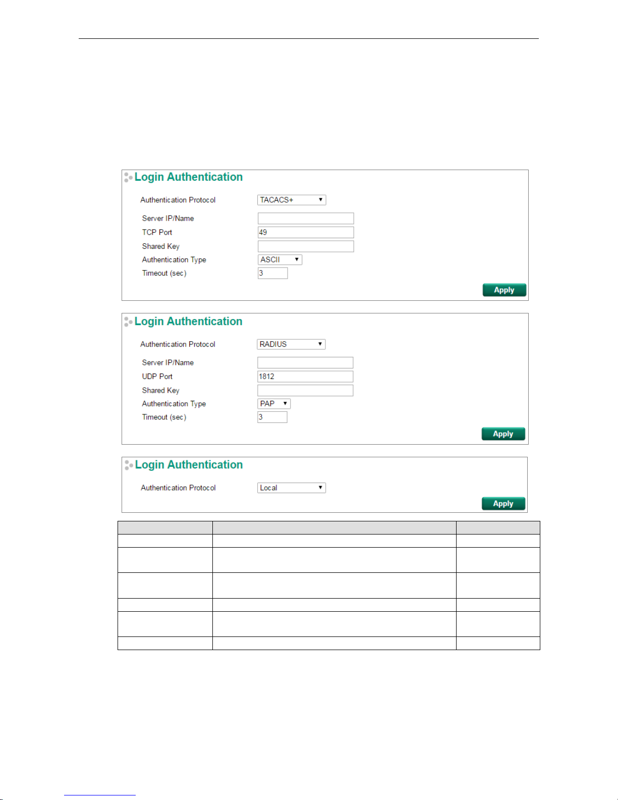
PT-G7828/G7728 Featured Functions
3-68
There are five combinations for users:
1. TACACS+, Local: Check TACACS+ database first. If checking the TACACS+ database fails, then check the
Local database
2. RADIUS, Local: Check RADIUS database first. If checking the RADIUS database fails, then check the Local
database
3. TACACS+: Only check TACACS+ database
4. RADIUS: Only check the RADIUS database
5. Local: Only check the Local database
Setting Description Factory Default
Authentication Protocol Authentication protocol selection. Local
Server IP/Name Sets the IP address of an external
TACACS+/RADIUS server as
the authentication database.
None
TCP/UDP Port
Sets the communication port of an external TACACS+/RADIUS
server as the authentication database.
TACACS+: 49
RADIUS: 1812
Shared Key Sets specific characters for server authentication verification. None
Authentication Type Authentication mechanism selection. ASCII, PAP, CHAP, and
MSCHAP are for TACACS+; PAP and CHAP are for RADIUS.
ASCII for TACACS+
PAP for RADIUS
Timeout (sec) The timeout period for waiting for a server response. 3
www.ipc2u.ru
www.moxa.pro
Page 81
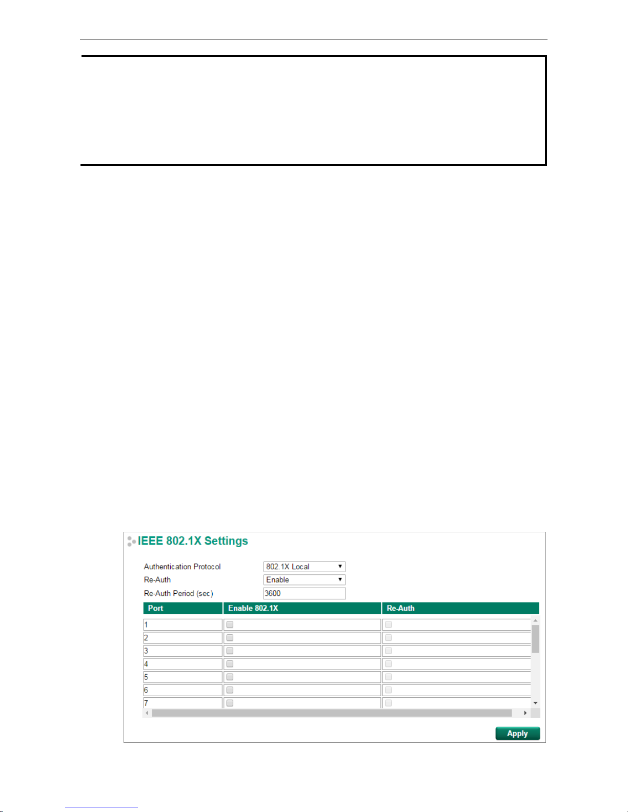
PT-G7828/G7728 Featured Functions
3-69
NOTE
The account privilege level is authorized
under service type settings in RADIUS, and the privilege level is
under
TACACS+.
RADIUS Server
• RADIUS Service type = 6 = read/write = administrator
• RADIUS Service type = 1 = read only = user
TACACS+ Server
• TACACS+ privilege level= 15 = read/write = administrator
• TACACS+ privilege level= 1 to 14 = read only = user
IEEE 802.1X Settings
The IEEE 802.1X standard defines a protocol for client/server-based access control and authentication. The
protocol restricts unauthorized clients from connecting to a LAN through ports that are open to the Internet,
and which otherwise would be readily accessible. The purpose of the authentication server is to check each
client that requests access to the port. The client is only allowed access to the port if the client’s permission is
authenticated.
Three components are used to create an authentication mechanism based on 802.1X standards:
Client/Supplicant, Authentication Server, and Authenticator.
Client/Supplicant: The end station that requests access to the LAN and switch services and responds to the
requests from the switch.
Authentication Server: The server that performs the actual authentication of the supplicant.
Authenticator: Edge switch or wireless access point that acts as a proxy between the supplicant and the
authentication server, requesting identity information from the supplicant, verifying the information with the
authentication server, and relaying a response to the supplicant.
The Moxa switch acts as an authenticator in the 802.1X environment. A supplicant and an authenticator
exchange EAPOL (Extensible Authentication Protocol over LAN) frames with each other. We can either use an
external RADIUS server as the authentication server, or implement the authentication server in the Moxa
switch by using a Local User Database as the authentication look-up table. When we use an external RADIUS
server as the authentication server, the authenticator and the authentication server exchange EAP frames.
Authentication can be initiated either by the supplicant or the authenticator. When the supplicant initiates the
authentication process, it sends an EAPOL-Start frame to the authenticator. When the authenticator initiates
the authentication process or when it receives an EAPOL Start frame, it sends an EAP Request/Identity
frame to ask for the username of the supplicant.
www.ipc2u.ru
www.moxa.pro
Page 82
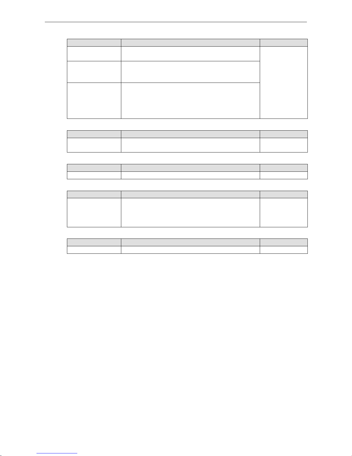
PT-G7828/G7728 Featured Functions
3-70
Authentication Protocol
Setting Description Factory Default
802.1X Local
(Max. of 32 users)
Select this option when setting the 802.1X
Local User Database
as the authentication database.
802.1X Local
RADIUS Select this option to set an external RADIUS server as the
authentication database. The authentication mechanism is
EAP-MD5.
RADIUS, 802.1X Local Select this option to make
using an external RADIUS server as
the authentication database the first priority. The
authentication mechanism is EAP-MD5. The second priority is
to set the 802.1X Local User Database as the authentication
database.
Re-Auth (Global)
Setting Description Factory Default
Enable/Disable Select enable to require re-authentication of the client after a
preset time period of no activity has elapsed.
Enable
Re-Auth Period (sec)
Setting Description Factory Default
60 to 65535 Sets the Re-Auth period 3600
Enable 802.1X
Setting
Description
Factory Default
Select/Deselect Select the checkbox under the 802.1X column to enable IEEE
802.1X for one or more ports. All end stations must enter
usernames and passwords before access to these ports is
allowed.
Deselect
Re-Auth
Setting Description Factory Default
Select/Deselect Select enable to require re-authentication of the client by port Deselect
www.ipc2u.ru
www.moxa.pro
Page 83
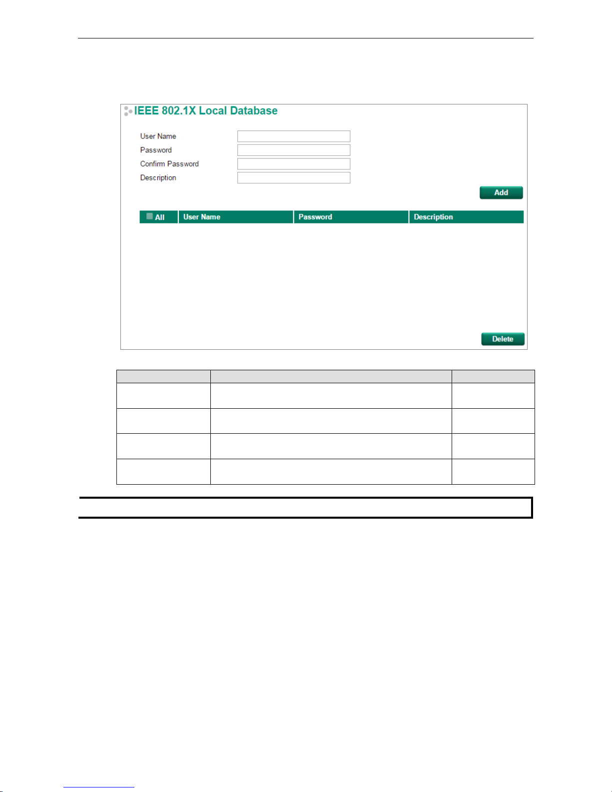
PT-G7828/G7728 Featured Functions
3-71
IEEE 802.1X Local Database
When selecting the 802.1X Local as the authentication protocol, set the IEEE 802.1X Local Database first.
IEEE 802.1X Local Database Setup
Setting Description Factory Default
User Name
(Max. of 30 characters)
User Name for the Local User Database None
Password
(Max. of 16 characters)
Password for the Local User Database None
Confirm Password
(Max. of 16 characters)
Confirm Password for the Local User Database None
Description
(Max. of 30 characters)
Description for the Local User Database None
NOTE
The user name for the
IEEE 802.1X Local Database is case-insensitive.
www.ipc2u.ru
www.moxa.pro
Page 84
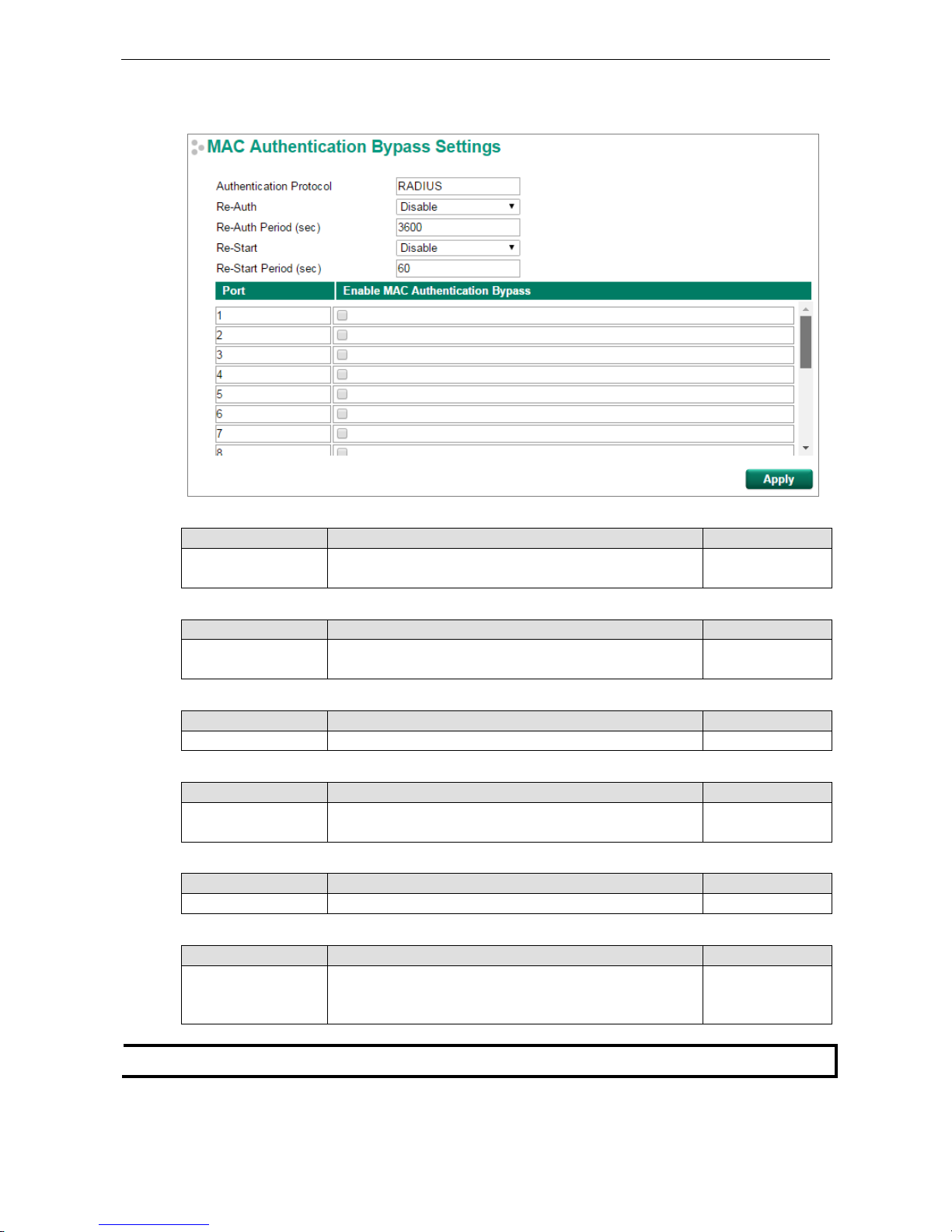
PT-G7828/G7728 Featured Functions
3-72
MAC Authentication Bypass Settings
Authentication Protocol
Setting Description Factory Default
RADIUS RADIUS is the only authentication protocol of the MAC
Authentication Bypass
RADIUS
Re-Auth
Setting Description Factory Default
Enable/Disable Select enable to require re-authentication of the client after a
preset time period of no activity has elapsed
Disable
Re-Auth Period (sec)
Setting Description Factory Default
60 to 65535 Sets the Re-Auth period 3600
Re-Start
Setting Description Factory Default
Enable/Disable Select enable to require a present time period to re-start
authentication after failure of authentication
Disable
Re-Start Period (sec)
Setting Description Factory Default
5 to 300 Sets the Re-Start period 60
Enable MAC Authentication Bypass
Setting
Description
Factory Default
Select/Deselect Check the checkbox under the MAC Authentication Bypass
column to enable MAC Authentication Bypass for one or more
ports
Deselect
NOTE
If RADIUS Server is case sensitive,
use lower-case characters for the username and password.
www.ipc2u.ru
www.moxa.pro
Page 85
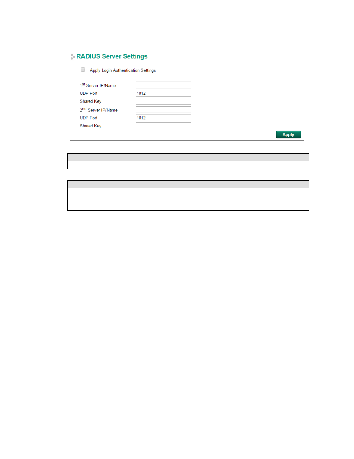
PT-G7828/G7728 Featured Functions
3-73
RADIUS Server Settings
Apply Login Authentication Setting
Setting Description Factory Default
Select/Deselect Enables using the same setting as Auth Server. Deselect
Server Setting
Setting Description Factory Default
Server IP/Name Specifies the IP/name of the server None
Server Port Specifies the port of the server 1812
Server Shared Key Specifies the shared key of the server None
www.ipc2u.ru
www.moxa.pro
Page 86
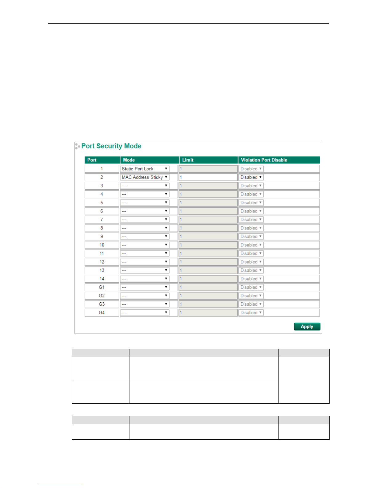
PT-G7828/G7728 Featured Functions
3-74
Port Security
Moxa switches provide a Port Security function that lets packets with allowed MAC Addresses access the
switch’s ports. Two Port Security modes are supported: Static Port Lock and MAC Address Sticky.
Static Port Lock: Allows users to configure specific MAC addresses that are allowed to access the port.
MAC Address Sticky: Allows users to configure the maximum number of MAC addresses (the Limit) that a
port can “learn.” Users can configure what action should be taken (under Violation Port Disable) when a new
MAC address tries to access a port after the maximum number of MAC addresses have already been learned.
The total number of allowed MAC addresses cannot exceed 1024.
Port Security Mode
Mode
Setting Description Factory Default
Static Port Lock The switch will block unauthorized MAC addresses and allow
access to packets with a MAC address defined in the Static
Unicast MAC Address Table.
None
MAC Address Sticky If Limit is set to n, the switch will learn the first n MAC
addresses that access the port, and automatically store
them in
the MAC Address Control Table.
Limit (only active for MAC Address Sticky)
Setting Description Factory Default
1 to 1024 The maximum number of learned MAC addresses allowed for
that port.
1
www.ipc2u.ru
www.moxa.pro
Page 87
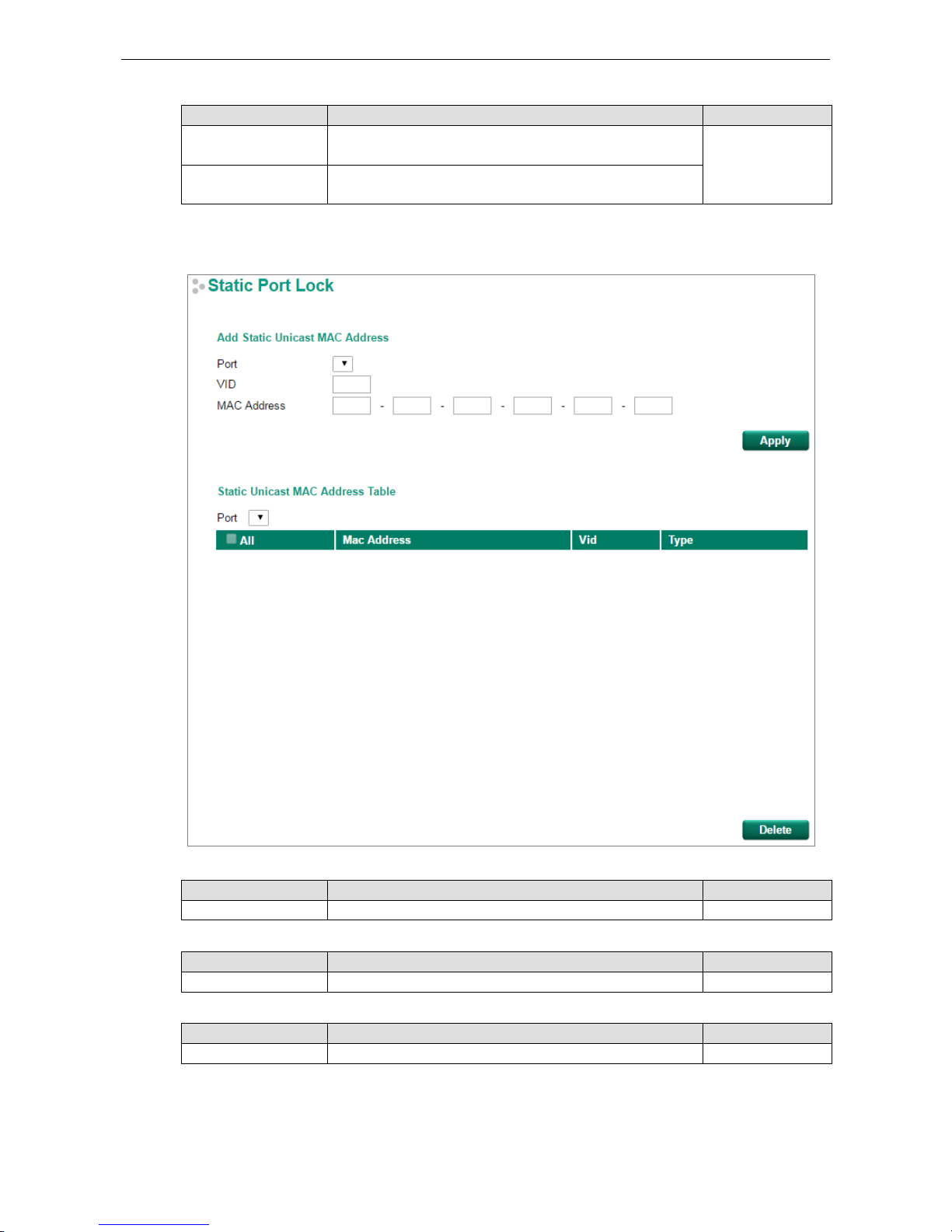
PT-G7828/G7728 Featured Functions
3-75
Violation Port Disable (only active for MAC Address Sticky)
Setting Description Factory Default
Disable When the port receives a packet with an unlearned MAC
address, the packet will be discarded.
Disable
Enable When the port receives a packet with an unlearned MAC
address, the port will be disabled.
Static Port Lock
Port Number
Setting Description Factory Default
Port Number
Associates the static address to a dedicated port
None
VID
Setting Description Factory Default
VLAN ID Associates the static address to a dedicated VLAN on the port None
MAC Address
Setting Description Factory Default
MAC Address Adds the static unicast MAC address into the address table None
www.ipc2u.ru
www.moxa.pro
Page 88
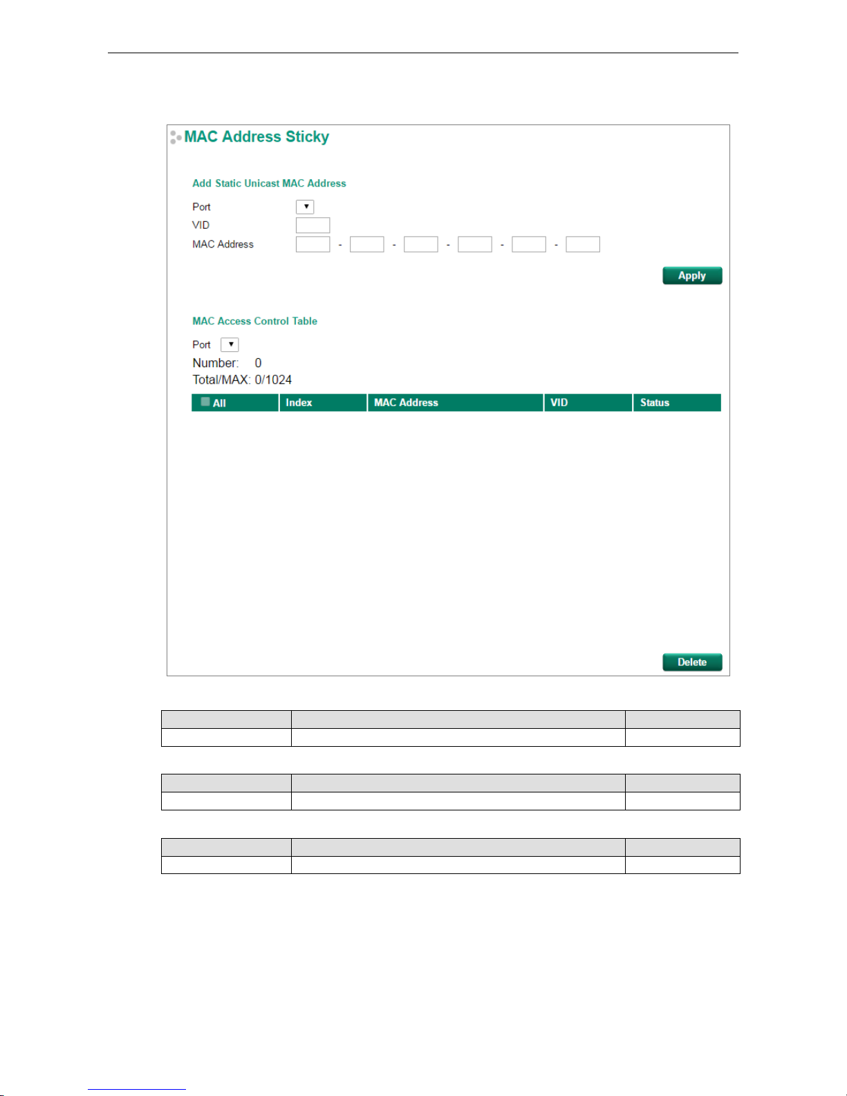
PT-G7828/G7728 Featured Functions
3-76
MAC Address Sticky
Port Number
Setting Description Factory Default
Port Number Associates the static address to a dedicated port None
VID
Setting Description Factory Default
VLAN ID Associates the static address to a dedicated VLAN on the port None
MAC Address
Setting Description Factory Default
MAC Address Adds the static unicast MAC address into the address table None
www.ipc2u.ru
www.moxa.pro
Page 89
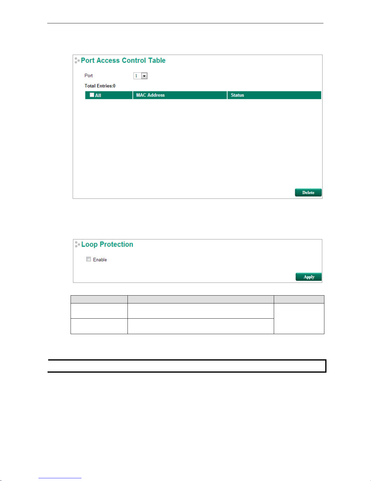
PT-G7828/G7728 Featured Functions
3-77
Port Access Control Table
The port status will be indicated as authorized or unauthorized.
Loop Protection
Enable Loop Protection
Setting Description Factory Default
Enable Select the Enable checkbox to enable the loop protection
function.
Disable
Disable Deselect the Enable checkbox to disable the loop protection
function.
Access Control List
NOTE
PT
-G7728 switches only support Ingress ACL.
Access control lists (ACLs) increase the flexibility and security of networking management. ACLs provide traffic
filtering capabilities for ingress and egress packets. Moxa ACLs can manage filter criteria for a diverse range of
protocols and allow users to configure customized filter criteria. For example, users can deny access to specific
source or destination IP/MAC addresses. The Moxa ACL configuration interface is easy to use. Users can quickly
establish filtering rules, manage rule priorities, and view overall settings on the display page.
www.ipc2u.ru
www.moxa.pro
Page 90

PT-G7828/G7728 Featured Functions
3-78
The ACL Concept
What is ACL?
An access control list is a basic traffic filter for ingress and egress packets. The ACL can examine each Ethernet
packet’s information and take the necessary action. Moxa Layer 3 switches provide complete filtering
capabilities. Access list criteria could include the source or destination IP address of the packets, the source or
destination MAC address of the packets, IP protocols, or other information. The ACL can check these criteria to
decide whether to permit or deny access to a packet.
Benefits of ACL
ACLs support per interface, per packet direction, and per protocol filtering capability. These features can
provide basic protection by filtering specific packets. The main benefits of an ACL are:
• Manage authority of hosts: An ACL can restrict specific devices through MAC address filtering. The user
can deny all packets or only permit packets that come from specific devices.
• Subnet authority management: Configure filtering rules for specific subnet IP addresses. An ACL can
restrict packets from or to specific subnets.
• Network security: The demand for networking security is growing. An ACL can provide basic protection
that works in a similar manner to an Ethernet firewall device.
• Control traffic flow by filtering specific protocols: An ACL can filter specific IP protocols such as TCP or
UDP packets.
How an ACL Works
The ACL working structure is based on access lists. Each access list is a filter. When a packet enters into or exits
from a switch, the ACL will compare the packet to the rules in the access lists, starting from the first rule. If a
packet is rejected or accepted by the first rule, the switch will drop or pass this packet directly without checking
the rest of the lower-priority rules. In other words, Access Control Lists have “Priority Index” as an attribute to
define the priority in the web configuration console.
There are two types of settings for an ACL: list settings and rule settings. In order to be created, an Access
Control List needs the following list settings: Name, Priority Index, Filter Type, and Ports to Apply. Once created,
each Access Control List has its own set of rule settings. Priority Index represents the priority of the names in
the access list. Names at Priority Index 1 have first priority in packet filtering. The Priority Index is adjustable
whenever users need to change the priority. Two types of packet filtering can be used:
• IP based
• MAC Based
The filter type defines whether the access list will examine packets based on IP or MAC address. The type
affects what detailed rules can be edited. You can then assign the ports you would like to apply the list to. You
can also define Ingress and Egress per port.
After adding a new access control list, you can also create new rules for the access control list. Each ACL group
accepts 10 rules. Rules can filter packets by source and destination IP/MAC address, IP protocol, TCP/UDP Port,
Ethernet Type, and VLAN ID.
After all rules are set, the ACL starts to filter the packets by the rule with the highest Priority Index (smaller
number, higher priority). Once a rule denies or accepts its access, the packet will be dropped or passed.
www.ipc2u.ru
www.moxa.pro
Page 91
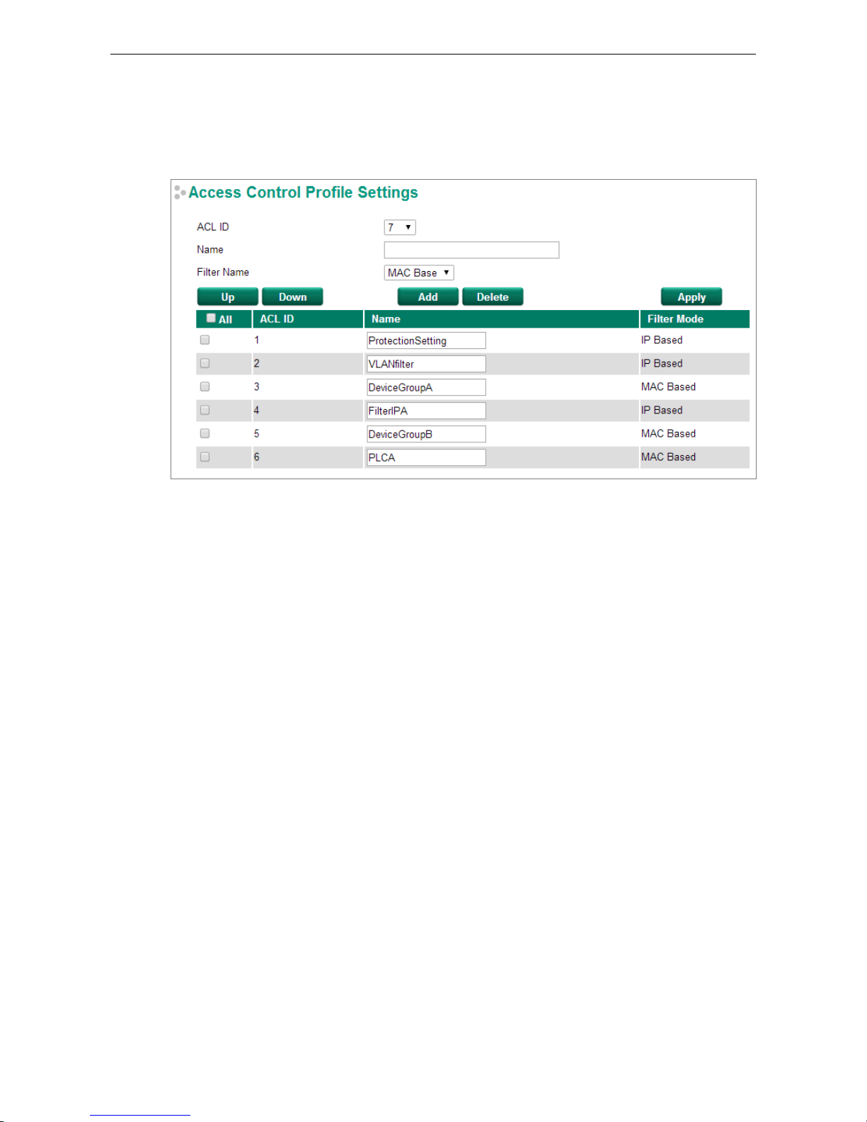
PT-G7828/G7728 Featured Functions
3-79
Access Control List Configuration and Setup
Access Control Profile Settings
On this page, you can configure two settings: (1) Add/Modify Access Control list, and (2) Adjust ACL ID.
Add/Modify Access Control List
This function lets you add a new access control profile or modify an existing access control profile. The
operation depends on the ACL ID you select. If the selected ACL ID is still empty, you can start by creating a
new access control profile. Parameters for editing are as follows:
• ACL ID: The ACL checking sequence is based on these IDs. Smaller ID numbers have a higher priority for
packet filtering. If a packet is filtered by an access control profile with a higher priority, those access control
profiles with a lower priority will not be executed.
Note that the ACL ID is not unique with respect to the profile name. The ID changes when swapping the
priority of different access control profiles.
The maximum Priority Index number is 16.
• Name: You can name the access control profile in this field.
• Filter Name: Select filtering by either IP or MAC address. Detailed settings can be configured in the Access
Control Rule Settings page.
If a selected ACL ID is already in the access control list, then you can modify the parameters listed above. After
the configuration is complete, click Apply to confirm the settings. A new list will appear in the Access Control
List Table.
Adjust ACL ID
Changing an established access control profile’s priority is easy. Moxa provides a simple interface to let you
easily adjust the priority. Follow the three steps below to adjust the priority:
Step 1: Select the profile
Step 2: Click the Up/Down button to adjust the sequence. The ACL ID will change with the profile’s position.
Step 3: Click the Apply button to confirm the settings.
www.ipc2u.ru
www.moxa.pro
Page 92

PT-G7828/G7728 Featured Functions
3-80
Access Control Rule Settings
You can edit access control rules on this page. Each ACL includes up to 10 rules. First, select the access control
profile you would like to edit based on the ACL ID, and then set up the rule content and ingress/egress ports.
After configuring, click the Add button to add the rule to the list. Finally, click Apply to activate the settings.
An access control rule displays setting options based on the filtering type used:
IP Based (Layer 2 Device)
www.ipc2u.ru
www.moxa.pro
Page 93

PT-G7828/G7728 Featured Functions
3-81
IP Based (Layer 3 Device)
• Action: Whether to deny or permit access if the rule criterion is met.
• Source (Destination) IP Address / IP Address Mask: Defines the IP address rule. By using the mask,
you can assign specific subnet ranges to filter. It allows checking the source or destination of the packet.
Choose Any if you do not need to use this criteria.
• IP Protocol: Select the type of protocols to be filtered. Moxa provides ICMP, IGMP, IP over IP, TCP, and
UDP as options in this field.
• TCP/UDP Source (Destination) Port: If TCP or UDP are selected as the filtering protocol, these fields will
allow you to enter port numbers for filtering.
www.ipc2u.ru
www.moxa.pro
Page 94

PT-G7828/G7728 Featured Functions
3-82
MAC Based (Layer 2 Device)
www.ipc2u.ru
www.moxa.pro
Page 95

PT-G7828/G7728 Featured Functions
3-83
MAC Based (Layer 3 Device)
• Action: Whether to deny or permit access if the rule criterion is met.
• Source (Destination) MAC Address / MAC Address Mask: Defines the MAC address rule. By using the
mask, you can assign specific MAC address ranges to filter. It allows checking the source or destination of
the packet. Choose Any if you do not need to use this criterion.
• Ethernet Type: Select the type of Ethernet protocol to filter. Options are IPv4, ARP, RARP, IPv6, IEE802.3,
PROFIENT, LLDP, and IEEE1588.
• VLAN ID: Enter a VLAN ID you would like to filter by.
Once ready, click the Add button to add the rule to the list and set up the ingress/egress ports, and then click
Apply to activate the settings.
www.ipc2u.ru
www.moxa.pro
Page 96
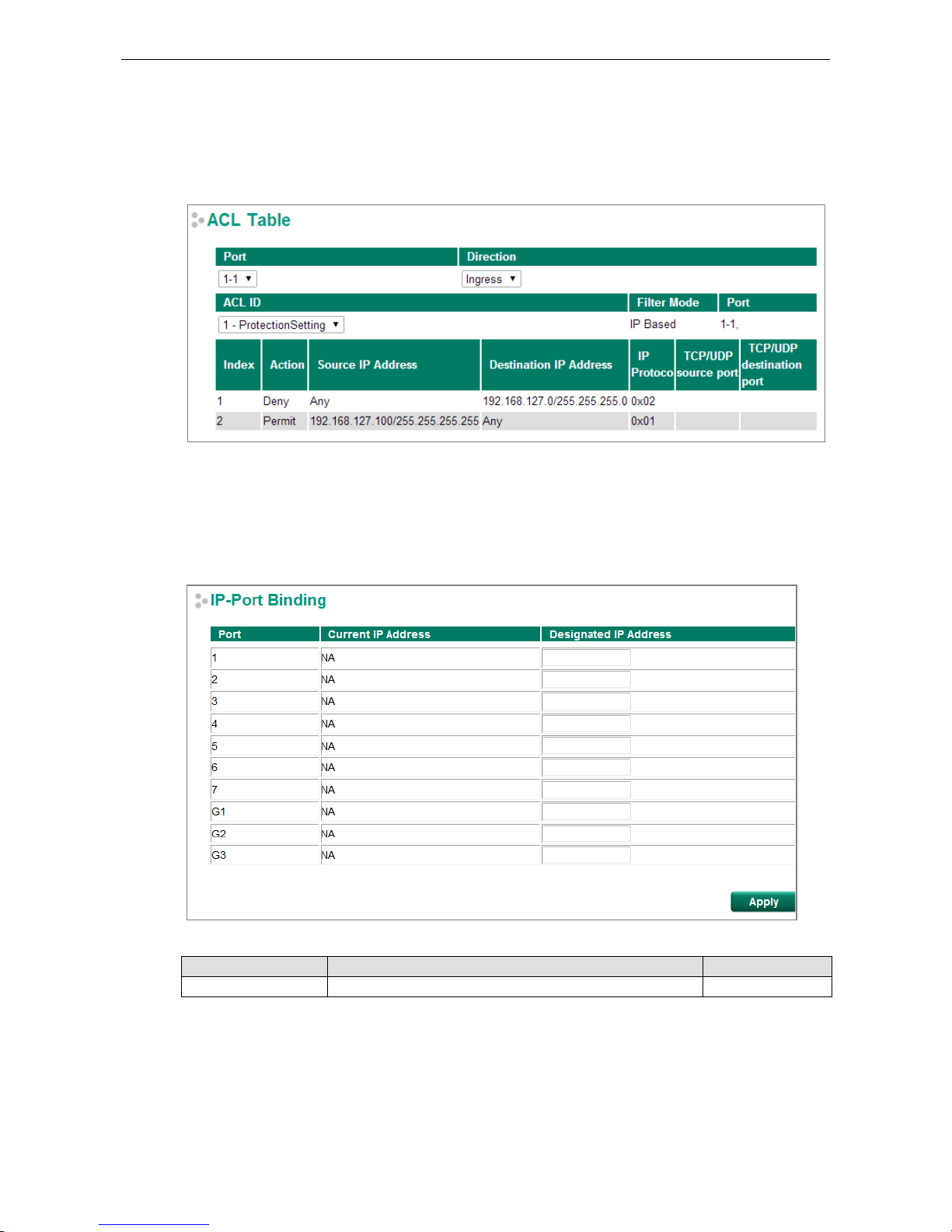
PT-G7828/G7728 Featured Functions
3-84
Access Control List Table
The Access Control List Table page provides a complete view of all ACL settings. On this page, you can view the
rules by Ingress port, Egress port, or ACL ID. Click the drop-down menu to select Port or ACL ID, and all the
rules will be displayed in the table.
DHCP
IP-Port Binding
Designated IP Address
Setting Description Factory Default
IP Address Set the desired IP of connected devices. None
DHCP Relay Agent
The DHCP Relay Agent makes it possible for DHCP broadcast messages to be sent over routers. The DHCP Relay
Agent enables DHCP clients to obtain IP addresses from a DHCP server on a remote subnet, or those that are
not located on the local subnet.
www.ipc2u.ru
www.moxa.pro
Page 97
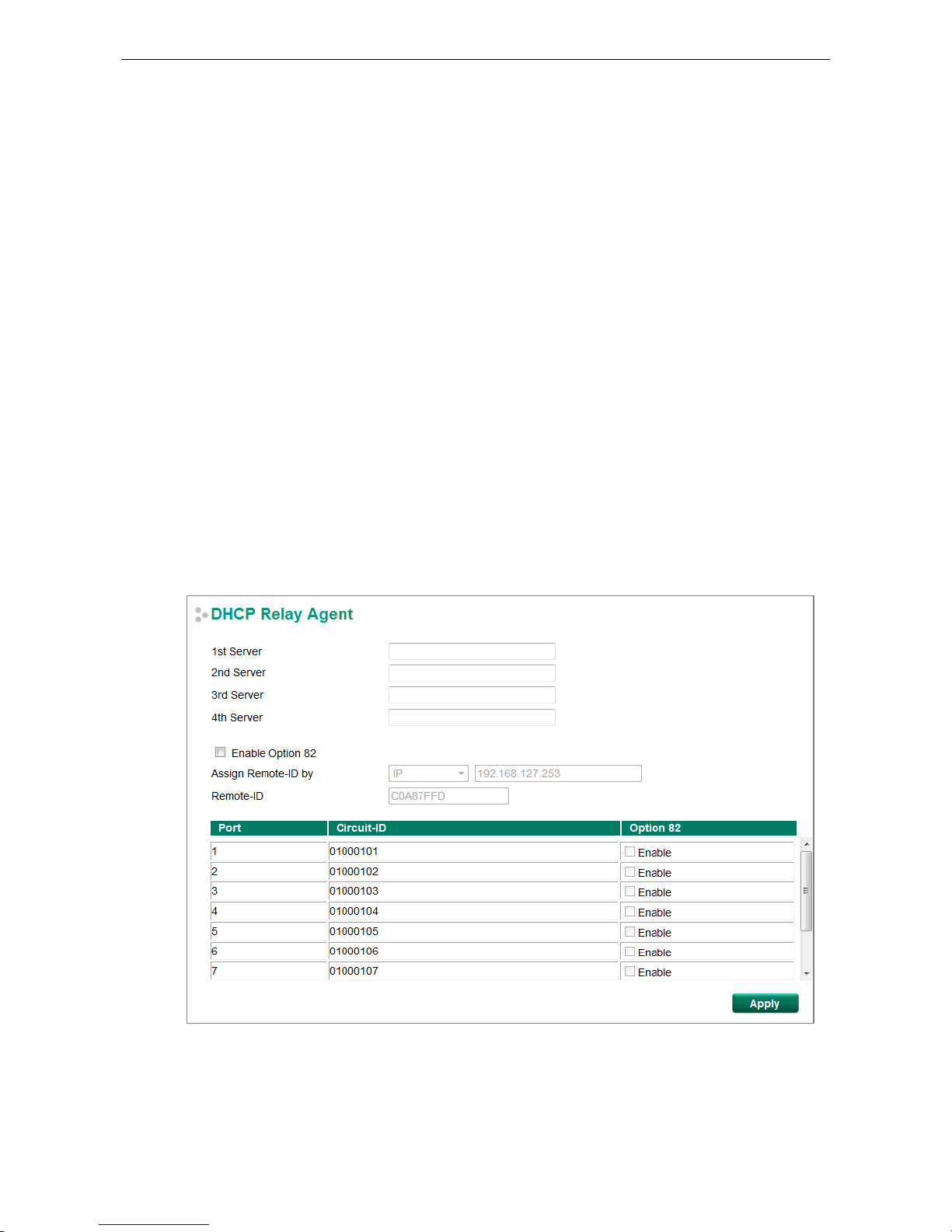
PT-G7828/G7728 Featured Functions
3-85
DHCP Relay Agent (Option 82)
Option 82 is used by the relay agent to insert additional information into the client’s DHCP request. The Relay
Agent Information option is inserted by the DHCP relay agent when forwarding client-originated DHCP packets
to a DHCP server. Servers can recognize the Relay Agent Information option and use the information to
implement IP addresses to Clients.
When Option 82 is enabled on the switch, a subscriber device is identified by the switch port through which it
connects to the network (in addition to its MAC address). Multiple hosts on the subscriber LAN can be connected
to the same port on the access switch and are uniquely identified.
The Option 82 information contains 2 sub-options, Circuit ID and Remote ID, which define the relationship
between the end device IP and the DHCP Option 82 server. The Circuit ID is a 4-byte number generated by the
Ethernet switch—a combination of physical port number and VLAN ID. The format of the Circuit ID is shown
below:
FF–VV–VV–PP
This is where the first byte “FF” is fixed to “01”, the second and the third byte “VV-VV” is formed by the port
VLAN ID in hex, and the last byte “PP” is formed by the port number in hex. For example:
01–00–0F–03 is the “Circuit ID” of port number 3 with port VLAN ID 15.
The “Remote ID” identifies the relay agent itself and can be one of the following:
1. The IP address of the relay agent.
2. The MAC address of the relay agent.
3. A combination of IP address and MAC address of the relay agent.
4. A user-defined string.
www.ipc2u.ru
www.moxa.pro
Page 98
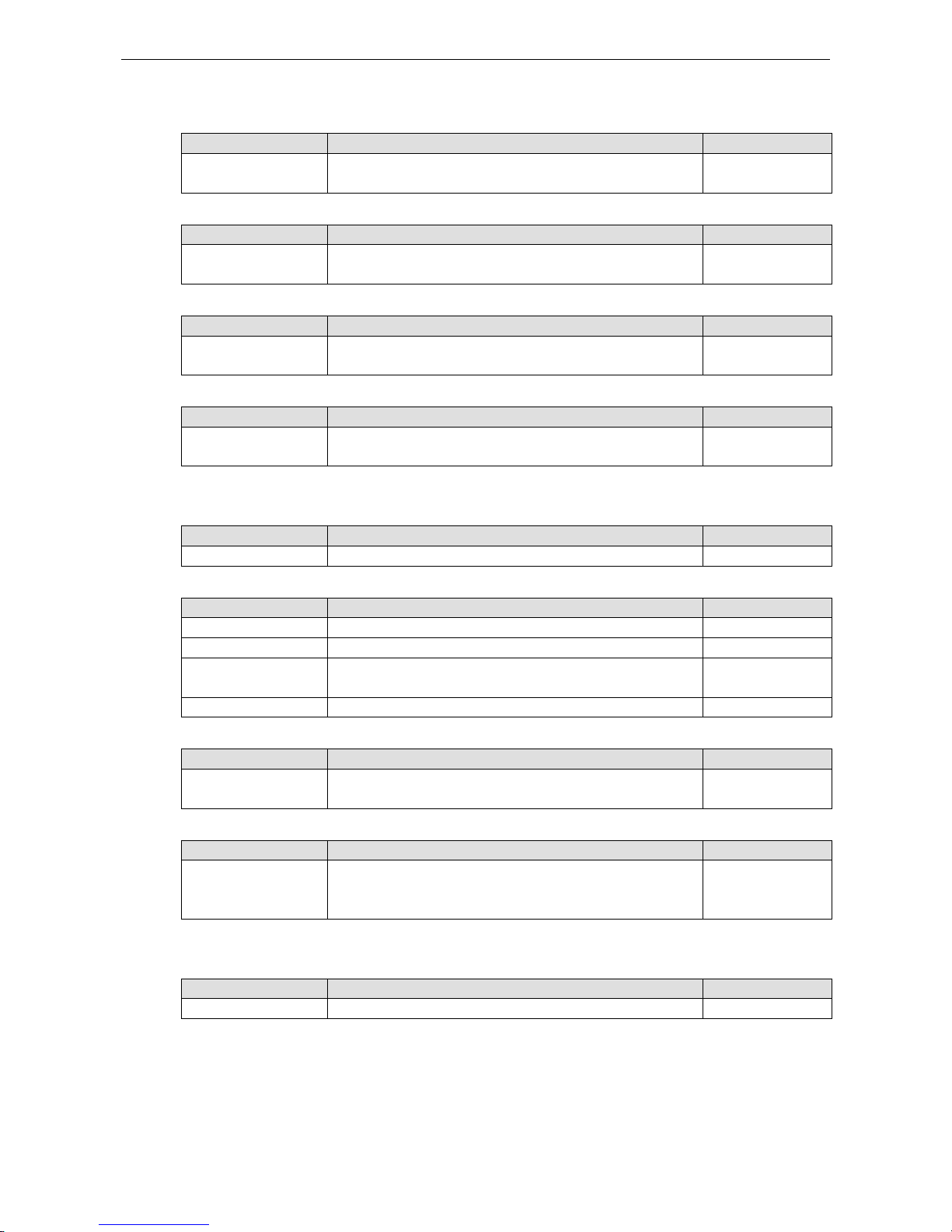
PT-G7828/G7728 Featured Functions
3-86
Server IP Address
1st Server
Setting Description Factory Default
IP address for the 1st
DHCP server
Assigns the IP address of the 1st DHCP server that the switch
tries to access.
None
2nd Server
Setting Description Factory Default
IP address for the 2nd
DHCP server
Assigns the IP address of the 2nd DHCP server that the switch
tries to access.
None
3rd Server
Setting Description Factory Default
IP address for the 3rd
DHCP server
Assigns the IP address of the 3rd DHCP server that the switch
tries to access.
None
4th Server
Setting Description Factory Default
IP address for the 4th
DHCP server
Assigns the IP address of the 4th DHCP server that the switch
tries to access.
None
DHCP Option 82
Enable Option 82
Setting Description Factory Default
Enable or Disable
Enable or disable the DHCP Option 82 function.
Disable
Assign Remote-ID by
Setting Description Factory Default
IP Uses the switch’s IP address as the remote ID sub. IP
MAC Uses the switch’s MAC address as the remote ID sub. IP
Client-ID Uses a
combination of the switch’s MAC address and IP address
as the remote ID sub.
IP
Other Uses the user-designated ID sub. IP
Value
Setting Description Factory Default
Max. of 12 characters Displays the value that was set. Complete this field if type is set
to Other.
Switch IP address
Remote-ID
Setting Description Factory Default
read-only
The actual hexadecimal value configured in the DHCP server for
the Remote-ID. This value is automatically generated
according to the Value field. Users cannot modify it.
C0A87FFD
DHCP Function Table
Enable
Setting Description Factory Default
Enable or Disable Enable or disable the DHCP Option 82 function for this port. Disable
www.ipc2u.ru
www.moxa.pro
Page 99
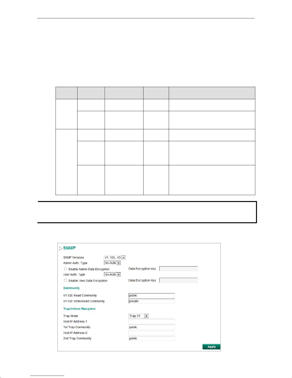
PT-G7828/G7728 Featured Functions
3-87
SNMP
The Moxa switch supports SNMP V1, V2c, and V3. SNMP V1 and SNMP V2c use a community string match for
authentication, which means that SNMP servers access all objects with read-only or read/write permissions
using the community strings public and private by default. SNMP V3 requires that you select an authentication
level of MD5 or SHA, and is the most secure protocol. You can also enable data encryption to enhance data
security.
Supported SNMP security modes and levels are shown in the following table. Select the security mode and level
that will be used to communicate between the SNMP agent and manager.
Protocol
Version
UI Setting Authentication Encryption Method
SNMP V1,
V2c
V1, V2c Read
Community
Community string No Uses a community string match for
authentication.
V1, V2c
Write/Read
Community
Community string No Uses a community string match for
authentication.
SNMP V3 No-Auth No No Uses an account with admin or user to access
objects
MD5 or SHA Authentication
based on MD5 or
SHA
No Provides authentication based on HMAC-MD5,
or HMAC-SHA algorithms. 8-character
passwords are the minimum requirement for
authentication.
MD5 or SHA Authentication
based on MD5 or
SHA
Data
encryption
key
Provides authentication based on HMAC-MD5
or HMAC-SHA
algorithms, and data encryption
key. 8-character passwords and a data
encryption key are the minimum requirements
for authentication .and encryption.
NOTE
The username and password of SNMP V3 are the same as the username and password of User Account.
A
ccounts with admin privilege have read/write access to all configuration parameters. Accounts with user
authority
only have read access to configuration parameters.
These parameters are configured on the SNMP page. A more detailed explanation of each parameter is given
below the figure.
www.ipc2u.ru
www.moxa.pro
Page 100

PT-G7828/G7728 Featured Functions
3-88
SNMP Read/Write Settings
SNMP Versions
Setting Description Factory Default
V1, V2c, V3, or
V1, V2c, or
V3 only
Specifies the SNMP protocol version used to manage the
switch.
V1, V2c
V1, V2c Read Community
Setting Description Factory Default
Max. 30 characters
Specifies the community string to authenticate the SNMP agent
for read-only access. The SNMP agent will access all objects
with read-only permissions using this community string.
Public
V1, V2c Write/Read Community
Setting Description Factory Default
Max. 30 characters
Specifies the community string to authenticate the SNMP agent
for read/write access. The SNMP server will access all objects
with read/write permissions using this community string.
Private
For SNMP V3, two levels of privilege are available for accessing the Moxa switch. Admin privilege provides
access and authorization to read and write the MIB file. User privilege only allows reading the MIB file.
Admin Auth. Type (for SNMP V1, V2c, V3, and V3 only)
Setting
Description
Factory Default
No-Auth Allows the admin account to access objects without
authentication.
No
MD5-
Auth
Authentication will be based on the HMAC-MD5 algorithms.
8-character passwords are the minimum requirement for
authentication.
No
SHA-
Auth
Authentication will be based on the HMAC-SHA algorithms.
8-character passwords are the minimum requirement for
authentication.
No
Enable Admin Data Encryption Key (for SNMP V1, V2c, V3, and V3 only)
Setting Description Factory Default
Enable
Enables data encryption using the specified data encryption key
(between 8 and 30 characters).
No
Disable Specifies that data will not be encrypted. No
User Auth. Type (for SNMP V1, V2c, V3 and V3 only)
Setting Description Factory Default
No-Auth Allows the admin account and user account to access objects
without authentication.
No
MD5-Auth Authentication will be based on the HMAC-MD5 algorithms.
8-character passwords are the minimum requirement for
authentication.
No
SHA-Auth Authentication will be based on the HMAC-SHA algorithms.
8-character passwords are the minimum requirement for
authentication.
No
Enable User Data Encryption Key (for SNMP V1, V2c, V3 and V3 only)
Setting
Description
Factory Default
Enable Enables data
encryption using the specified data encryption key
(between 8 and 30 characters).
No
Disable No data encryption No
www.ipc2u.ru
www.moxa.pro
 Loading...