

Moxa Technologies PT-G7728, PT-G7828 Quick Installation Manual

P/N: 1802077280410
*1802077280410*
PT-G7728/G7828
Quick Installation Guide
Edition 1.0, December 2017
Technical Support Contact Information
www.moxa.com/support
Moxa Americas:
Toll
-free: 1-888-669-2872
Tel:
1-714-528-6777
Fax:
1-714-528-6778
Moxa China (Shanghai office):
Toll
-free: 800-820-5036
Tel:
+86-21-5258-9955
Fax:
+86-21-5258-5505
Moxa Europe:
Tel:
+49-89-3 70 03 99-0
Fax:
+49-89-3 70 03 99-99
Moxa Asia-Pacific:
Tel:
+886-2-8919-1230
Fax:
+886-2-8919-1231
Moxa India:
Tel:
+91-80-4172-9088
Fax:
+91-80-4132-1045
2017 Moxa Inc. All rights reserved.
www.ipc2u.ru
www.ipc2u.com
www.moxa.pro

- 2 -
Package Checklist
Moxa’s PT-G7728/G7828 industrial rackmount switch is shipped with the
following items. If any of these items are missing or damaged, please
contact your customer service representative for assistance.
• 1 PT-G7728 or G7828 switch
• USB cable (Type A male to Micro USB type B)
• 2 protective caps for unused ports, 3 protective caps for unused USB
ports
• 2 rackmount ears
• Quick installation guide (printed)
• Substance Disclosure Table
• Product Certificate of Quality Inspection (Simplified Chinese)
• Product Notices (Simplified Chinese)
• Warranty card
NOTE
You can find information and software downloads on the relevant
product pages located on Moxa’s website: www.moxa.com
Default Settings
• Default IP address: 192.168.127.253
• Default Subnet Mask: 255.255.255.0
• Default Usernames: admin, user
• Default Password: moxa
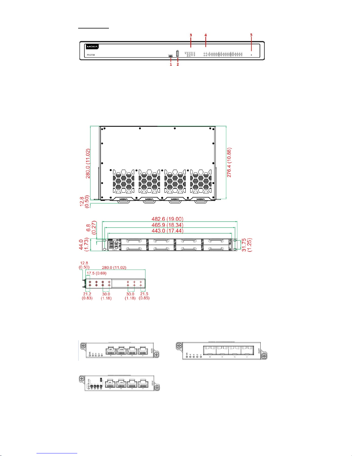
Panel Layouts
Front Panel
1. System status LEDs (from left to right)
STATE LED indicator, MSTR/HEAD LED indicator, FAULT LED
indicator, CPLR/Tail LED indicator, SYNC LED indicator
2. USB console port
3. 2 x 10/100/1000BaseT(X) and 2 x 100/1000Base SFP ports
4. 100/1000Base SFP port status LEDs
5. 10/100/1000 BaseT(X) port status LEDs
6. Ethernet module slot 1
7. Ethernet module slot 2
8. Ethernet module slot 3
9. Ethernet module slot 4
10. Ethernet module slot 5
11. Ethernet module slot 6
12. Power module slot 1
13. Power module slot 2
14. Grounding screw
www.ipc2u.ru
www.ipc2u.com
www.moxa.pro
- 3 -
Rear View
1. USB console port
2. USB storage port
3. System LED indicators
4. Module and port LED indicators
5. Rest button
Dimensions
Unit: mm (inches)
Ethernet Modules
LM-7000H-4GTX
LM-7000H-4GSFP
LM-7000H-4GPoE
www.ipc2u.ru
www.ipc2u.com
www.moxa.pro
- 4 -
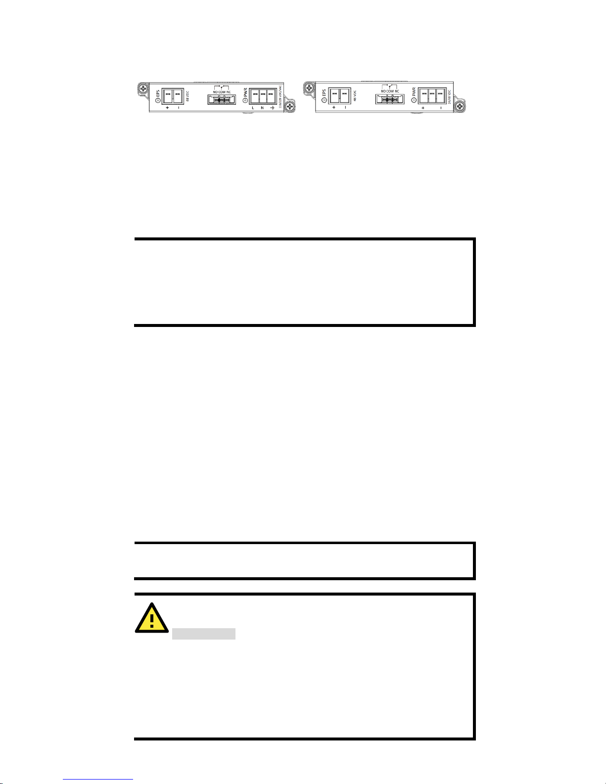
Power Modules
PWR-HV-P48
PWR-LV-P48
Rack Mounting Instructions
1. Elevated Operating Temperature: If installed in a closed or
multi-unit rack assembly, the operating ambient temperature of the
rack environment may be greater than room temperature.
Therefore, consideration should be given to installing the equipment
in an environment compatible with the maximum ambient
temperature (Tma) specified by the manufacturer.
NOTE
In order to ensure reliable operations, please make sure the
operating temp
erature of the environment does not exceed the
spec. When mounting a rack
-mounted switch with other
operatin
g units in a cabinet without forced ventilation, it is
recommended that 1U of space is reserved between each
rack-mounted switch and/or device.
2. Required Air Flow: Installation of the equipment in a rack should
be such that the amount of air flow required for safe operation of the
equipment is not compromised.
3. Mechanical Loading: Mounting of the equipment in the rack
should be such that a hazardous condition is not achieved due to
uneven mechanical loading.
4. Circuit Overloading: Consideration should be given to the
connection of the equipment to the supply circuit and the effect that
overloading of the circuits might have on overcurrent protection and
supply wiring. Appropriate consideration of equipment nameplate
ratings should be used when addressing this concern.
5. Reliable Grounding: Reliable grounding of rack-mounted
equipment should be maintained. Particular attention should be
given to supply connections other than direct connections to the
branch circuit (e.g. use of power strips).
NOTE
The rackmount ears can be installed on the front or rear of the
PT-G7728/G7828 switch.
ATTENTION
Safety First
!
Be sure to disconnect the power
cord before installing and/or
wiring your Ethernet Switch. Calculate the maximum possible
current in each power wire and common wire. Observe all
electrical codes dictating the maximum current allowable for each
wire size. If the current goes above the max
imum ratings, the
wiring could overheat,
which can cause
serious damage to your
equipment.
www.ipc2u.ru
www.ipc2u.com
www.moxa.pro
- 5 -
Connecting the Power Inputs
The PT-G7728/PT-G7828 switches support 2 types of power supply:
• PWR-HV-P48: one 110/220 VAC/VDC (90 to 264 VAC, 88 to 300 VDC),
one 48VDC PoE power input for PoE+ ports.
• PWR-LV-P48: one 24/48 VDC (18 to 72 VDC), one 48 VDC PoE power
input for PoE+ ports.
For the PWR-HV-P48, the 110/220 VAC/VDC power supplies provide
power to the switch. Separate 48 VDC power supplies are required to
provide power to all PoE+ ports (50 to 57 VDC is recommended for IEEE
802.3at devices).
For the PWR-LV-P48 models, the 24/48 VDC power supplies provide
power to the switch. Separate 48 VDC power supplies are required to
provide power to all PoE+ ports (50 to 57 VDC is recommended for IEEE
802.3at devices).
Wiring Requirements
WARNING
Do not disconnect modules or wires unless power has been
switched off or the area is kno
wn to be non-hazardous. The
device may only be connected to the supply voltage shown on the
type plate. The device is designed for operation with a Safety
Extra
-Low Voltage (SELV) or an isolated power supply, which
means that they may only be connected to
the supply voltage
connections and to the signal contact with a SELV or an isolated
power supply in compliance with IEC 60950
-1/EN 60950-
1 or UL
61010.
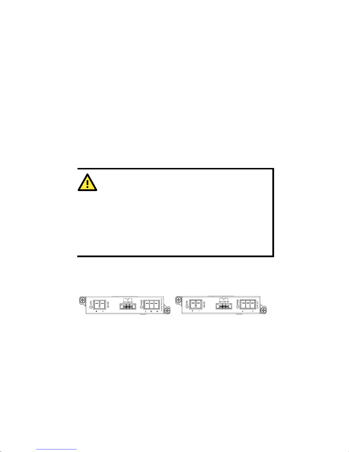
Power Terminal Blocks
The connection for power input and PoE external power supply is on the
power modules.
PWR-HV-P48
STEP 1: Insert the neutral/line (L/N/Ground) AC wires into the terminals.
STEP 2: Insert the terminal block connector into the terminal block
receptor.
PWR-LV-P48
STEP 1: Insert the negative/positive (-/+) DC wires into the terminals.
STEP 2: Insert the terminal block connector prongs into the terminal
block receptor.
www.ipc2u.ru
www.ipc2u.com
www.moxa.pro
 Loading...