

Page 1

P/N: 1802031500022
*1802031500022*
OnCell G3150A-LTE
Quick Installation Guide
Moxa OnCell Series
Edition 2.0, August 2017
Technical Support Contact Information
www.moxa.com/support
Moxa Americas:
Toll
-free: 1-888-669-2872
Tel:
1-714-528-6777
Fax:
1-714-528-6778
Moxa China (Shanghai office):
Toll
-free: 800-820-5036
Tel:
+86-21-5258-9955
Fax:
+86-21-5258-5505
Moxa Europe:
Tel:
+49-89-3 70 03 99-0
Fax:
+49-89-3 70 03 99-99
Moxa Asia-Pacific:
Tel:
+886-2-8919-1230
Fax:
+886-2-8919-1231
Moxa India:
Tel:
+91-80-4172-9088
Fax:
+91-80-4132-1045
2017 Moxa Inc. All rights reserved.
Page 2

- 2 -
Overview
The OnCell G3150A-LTE is a reliable, secure, LTE gateway with
state-of-the-art global LTE module. This 4G cellular gateway provides a
more reliable connection to your Ethernet network for cellular
applications.
To enhance industrial reliability, the OnCell G3150A-LTE features isolated
power inputs, which together with high-level EMS and wide-temperature
support give the OnCell G3150A-LTE the highest level of device stability
for any rugged environment. In addition, with dual-SIM GuaranLink and
dual power inputs, the OnCell G3150A-LTE supports network redundancy
to ensure uninterrupted connectivity.
The OnCell G3150A-LTE also comes with a 3-in-1 serial port for serial over
LTE cellular network communication. Use the OnCell G3150A-LTE to
collect data and exchange data with serial/Ethernet devices.
Package Checklist
Moxa’s OnCell G3150A-LTE is shipped with the following items. If any of
these items is missing or damaged, please contact your customer service
representative for assistance.
• 1 OnCell G3150A-LTE unit
• 2 2G/3G/4G antennas 2 dBi omni-directional with SMA male
connectors
• 1 DIN-rail mounting kit
• Quick installation guide (printed)
• Warranty card
Installation and Configuration
Before installing the OnCell G3150A-LTE, make sure that all items in the
package checklist are in the box. In addition, you will need access to a
notebook computer or PC equipped with an Ethernet port. The OnCell
G3150A-LTE has a default IP address that you must use when connecting
to the device for the first time.
Take the following steps to configure your OnCell G3150A-LTE. Refer to
the Panel Layout of the OnCell G3150A-LTE
section below for the location
of the ports and sockets.
Step 1: Insert a SIM card and turn on the OnCell G3150A-LTE
1. Use a screwdriver to loosen the screws and remove the SIM card
cover.
2. Insert one or two 2G/3G/4G SIM cards (full-sized SIM/1FF) into the
SIM card slots located on the bottom of the OnCell G3150A-LTE.
If you are only using one SIM card, insert it in the top slot (slot 1; the
card in slot 1 is referred to as SIM1).
By default, the SIM card in the slot 1 is treated as the primary card.
To change the default to SIM2 (the card in slot 2), log in to the
OnCell’s web UI, and configure SIM2 as the primary card. When the
OnCell device is turned on, it boots up based on the configuration
information stored on the primary SIM card.
3. Turn on the OnCell G3150A-LTE by connecting a power terminal
block to a DC power source (12 to 48 VDC). For details refer to the
Connecting the Power Input
section.
4. Reattach the cover.
Page 3

- 3 -
Step 2: Connect the OnCell G3150A-LTE to a notebook or PC
Since the OnCell G3150A-LTE supports MDI/MDI-X auto-sensing, you can
use either a straight-through cable or crossover cable to connect the
OnCell G3150A-LTE to a computer. See the
10/100BaseT(X) Ethernet
Port Connection section below for detailed instructions. If the LED
indicator on the OnCell G3150A-LTE’s LAN port lights up, it means a
connection has been established.
Step 3: Set up an IP address for the computer
Set an IP address on the same subnet as the OnCell G3150A-LTE. Since
the OnCell G3150A-LTE’s default IP address is 192.168.127.254, and the
subnet mask is 255.255.255.0, you should set the IP address of the
computer to 192.168.127.xxx and subnet mask to 255.255.255.0.
Step 4: Use the web-based manager to configure the OnCell
G3150A-LTE
Open your computer’s web browser and type http://192.168.127.254
in the address field to access the homepage of the web-based
management system. Before the homepage opens, you will need to enter
the username and password. For first-time configuration, enter the
default username and password given below:
Username: admin
Password: moxa
Click on the Login button.
ATTENTION
For security reasons, we strongly recommend changing the
password. To
change the password, select Maintenance
Username/Password
, and then follow the on-screen
instructions.
NOTE
You must either click the Save Configuration or the Restart
button for the configuration changes to take effect.
Page 4
- 4 -
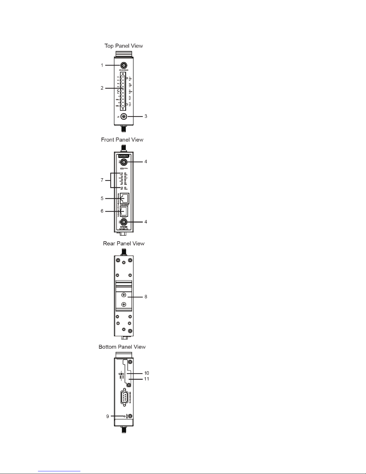
Panel Layout of the OnCell G3150A-LTE
1.
GPS antenna connector (female SMA)
2. Terminal block (top-down PWR1
and PWR2, 1 digital relay and 2
digital inputs)
3. Grounding screw (M5)
4. 2x2 MIMO antenna ports for LTE
(female SMA)
5. RS-232 serial console (RJ45)
6. 10/100 Base T(X) Ethernet port
(RJ45)
7. LED display
8. DIN-rail mounting kit
9. Reset button
10.
Dual SIM–SIM1
11.
Dual SIM–SIM2
Page 5
- 5 -
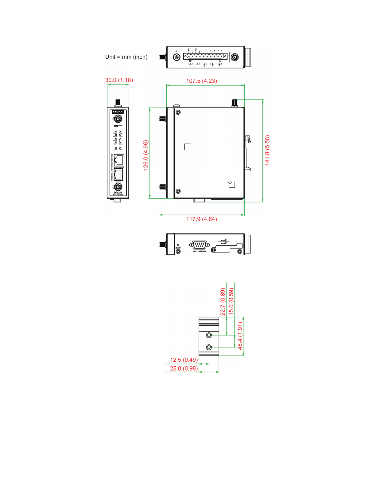
Device Dimensions
DIN-Rail Mounting
DIN-Rail Kit Dimensions
Unit = mm (inch)
The OnCell G3150A-LTE Series computers come with a DIN-rail kit
attached to the back panel. Mount the OnCell G3150A-LTE Series on
corrosion-free mounting rails that meet the EN 60715 standard.
Page 6

- 6 -
Installation
STEP 1: Insert the upper lip of the DIN rail into the top hook of the
DIN
-rail mounting kit.
STEP 2:
Press the OnCell G3150A-LTE S
eries towards the DIN rail until it
snaps into place.
To remove the OnCell G3150A-LTE from the DIN rail, reverse steps 1 and
2 above.
Wall Mounting (optional)
Wall-Mounting Kit
Dimension
s
Unit = mm (inch)
For some applications, it may be more convenient to mount the OnCell
G3150A-LTE to a wall, as illustrated below:
STEP 1:
Remove the aluminum
DIN-rail attachment plate
from the OnCell
G3150A
-LTE, and then
attach the wall
-mounting
plates with M3 screws, as
shown in the adjacent
diagram.
Page 7

- 7 -
STEP 2:
Mounting the OnCell
G3150A-LTE
to a wall requires 4
screws. Use the OnCell
G3150A-LTE
device, with wall
mount plates attached as a guide, to mark the correct
locations of the 4 screws. The heads of the screws
should be less than 6.0 mm in diameter, and the shafts
should be less than 3.5 mm in diameter, as shown in
the figure at the right.
NOTE
Test the screw head and shank size by inserting the screws into
one of the k
eyhole shaped apertures of the wall-mounting p
lates
before attaching the plates to the wall.
STEP 3:
Once the screws are fixed into the
wall, insert the four screw heads
through the large opening of the
keyhole
-shaped apertures, and
then slide the OnCell
G3150A-LTE
downwards, as indicated in the
accompanying diagram. Tighten
the four screws for added stability.
WARNING
• This equipment is intended to be used in a Restricted Access
Location, such as a dedicated computer room, where a
ccess
can only be gained by SERVICE PERSONS or by USERS who
have been instructed about the
fact that the metal chassis of
the equipment is extremely hot and may cause burns.
•
Service persons or users should pay special attention and
take special precautions before handling this equipment.
•
Only authorized, well-trained professionals should be allo
wed
to access the restricted access location. Access should be
controlled by the authority responsible for the location with
lock and key or a security identity system.
•
External metal parts are hot!!
Pay special attention or use
special protection before handling this equipment.
Wiring Requirements
WARNING
Safety First!
Be sure to disconnect the power cord before installing and/or
wiring your Moxa OnCell G3150A-LTE.
Page 8

- 8 -
Read and Follow These Guidelines
• Use separate paths to route wiring for power and devices. If power
wiring and device wiring paths must cross, make sure the wires are
perpendicular at the intersection point.
NOTE
Do not run signal or communications wiring and power wiring in
the same wire conduit. To avoid interference, wires with different
signal characteristics should be routed separately.
• You can use the type of signal transmitted through a wire to
determine which wires should be kept separate. The rule of thumb is
that wiring with similar electrical characteristics can be bundled
together.
• Keep input wiring and output wiring separate.
• It is strongly advised that you label wiring to all devices in the system
when necessary.
ATTENTION
This product is
intended to be supplied by a Listed Power Unit
marked “Class 2” or “LPS” and rated O/P: 9.6 W (12 V/0.78 A to
48 V/0.2 A).
ATTENTION
Make sure
that the external power adapter
(includes power cords
and plug assemblies) provided with the unit is certified and
suitable for use in your country.
Grounding the Moxa OnCell G3150A-LTE
Grounding and wire routing help limit the effects of noise due to
electromagnetic interference (EMI). Run the ground connection from the
ground screw to the grounding surface prior to connecting devices. The
minimum cross-sectional area of the grounding conductor should be
equal to that of the input cable.
ATTENTION
T
his product is intended to be mounted on a well-grounded
mounting surface, such as a metal panel. The potential difference
between the two ground potentials must be zero. If the potential
difference is NOT zero, the product could be permanently
damaged.
Page 9
- 9 -
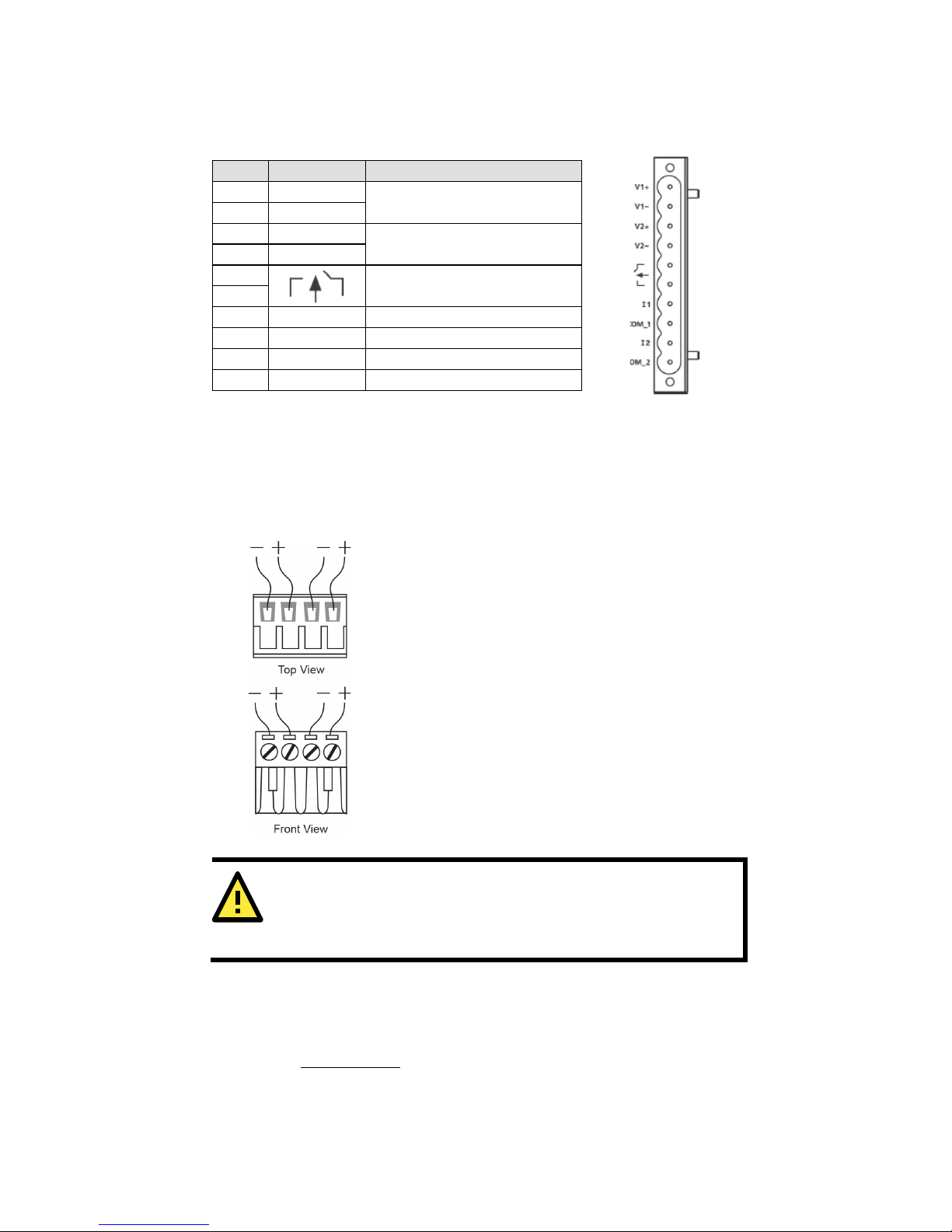
Connecting the Power Input
Pinouts for the Power Inputs and Relay Output
Pin
Name
Usage 1 V1+
DC Power Input 1
2
V1-
3
V2+
DC Power Input 2
4
V2-
5
Relay Output
6 7 I1
Digital Input
8
COM_1
Digital Input GND
9
I2
Digital Input
10
COM_2
Digital Input GND
Wiring the Redundant Power Inputs
The top two pairs of contacts of the 10-contact terminal block connector
located on the top panel of the OnCell G3150A-LTE are used as the two
DC inputs. Top and front views of the terminal block connector are shown
below:
STEP 1: Insert the negative/positive DC wires
into the
V-/V+ terminals.
STEP 2:
To keep the DC wires from pulling
loose,
use a small flat
-blade screwdriver to tight
en the
wire
-clamp screws on the front of the terminal
block connector.
STEP 3:
Insert the plastic terminal block
connector prongs into the terminal block
receptor, which is
located on the
top panel of the
OnCell
G3150A-LTE.
ATTENTION
Before connecting the
OnCell G3150A-LTE to the DC power
inputs, make sure that the DC power source voltage is stable.
Wiring the Relay Contact
The OnCell G3150A-LTE has one relay output, which consists of the two
contacts of the terminal block on the OnCell G3150A-LTE’s top panel.
Refer to the Specifications
section for detailed electrical requirement. The
relay contacts are used to indicate user-configured events. The two wires
attached to the relay contacts form an open circuit when a
user-configured event is triggered. If a user-configured event does not
occur, the relay circuit will be closed.
Page 10

- 10 -
Wiring the Digital Inputs
The OnCell G3150A-LTE has two sets of digital inputs—DI1 and DI2. Each
DI comprises of two contacts on the 6-pin terminal block connector
located on the top panel of the OnCell G3150A-LTE. Refer to the
Specifications
section for detailed information on isolated digital input
definition.
Communication Connections
10/100BaseT(X) Ethernet Port Connection
The 10/100BaseT(X) ports located on the front panel of the OnCell
G3150A-LTE are used to connect to Ethernet-enabled devices.
Pinouts for both MDI (NIC-type) ports and MDI-X (HUB/Switch-type)
ports are shown below:
MDI Port Pinouts
MDI-X Port Pinouts
8-pin RJ45
Pin
Signal
Pin
Signal
1
Tx+
1
Rx+
2
Tx- 2 Rx-
3
Rx+
3
Tx+
6
Rx- 6 Tx-
Serial DB9 Connection
The OnCell G3150A-LTE has one DB9 male port that supports RS-232,
RS-485-4W, RS-485-2W, and RS-422. The pin assignments are shown in
the table below:
DB9 Male
Connector
Pin
RS-232
RS-422/485-4w
RS-485-2w
1
DCD
TxD-(A)
– 2 RxD
TxD+(B)
–
3
TxD
RxD+(B)
Data+(B)
4
DTR
RxD-(A)
Data-(A)
5
GND
GND
GND
6
DSR – – 7 TRS – – 8 CTS – – 9 – – –
RS-232 Connection
The OnCell G3150A-LTE has one RS-232 (8-pin RJ45) console port
located on the front panel. Use either an RJ45-to-DB9 or RJ45-to-DB25
cable to connect the Moxa OnCell G3150A-LTE’s console port to your PC’s
COM port. You may then use a console terminal program to access the
OnCell G3150A-LTE for configuring the console configuration.
Page 11

- 11 -
Console Pinouts for 10-pin or 8-pin RJ45
10-Pin
Description
8-Pin 1 –
2 DSR
1 3 RTS
2 4 GND
3 5 TxD
4 6 RxD
5 7 –
6 8 CTS
7 9 DTR
8
10 –
NOTE
The pin numbers for both 8
-pin and 10-
pin RJ45 connectors (and
ports) are typically not labeled on the connector (or port). Refer
to the pinout diagram above for details.
LED Indicators
The front panel of the Moxa OnCell G3150A-LTE contains several LED
indicators. The function of each LED is described in the table below:
Type
Color
State
Description
Signal
(1 LED)
Green
Blinking
The number of blinks indicates the cellular
signal level (once the device is
connected to
a cellular network with an IP address.)
Interval between two blinks: 200 ms
Gap: 2 seconds
Number
of Blinks
Cellular
RSSI
RSSI Range
(dBm)
1
0 < SNR ≤
12
113 < RSSI ≤ -89
2 12 < SNR ≤
21
-89 < RSSI ≤ -73
3 22 < SNR ≤
31
-73 < RSSI ≤ -51
NOTE: The Cellular RSSI value is based on
the OnCell device signal strength returned
by the AT+ CSQ AT command. You can
also refer to the equivalent signal RSSI
Range (dBm) provided in the table above.
PWR1/
PWR2
Green
On
DC power source active
Off
Power is off
Ready
Green
On
System startup is complete and the system
is in operation.
Blinking
(slow at
1-sec
intervals)
The OnCell device has been located by the
Wireless Search Utility.
Off
Power is off, or device is booting up.
Page 12

- 12 -
Type
Color
State
Description
Fault
Red
On
Device is booting up, or IP address conflict.
Blinking
(slow at
1-sec
intervals)
Cannot get an IP address from the DHCP
server
Off
Power is off or no error condition exists.
2G / 3G
Amber
Blinking
(slow at
500-ms
intervals)
GSM/GPRS/EDGE is connected.
On
UMTS/HSPA is connected.
Off
GSM/GPRS/EDGE/UMTS/HSPA is
disconnected.
4G
Amber
On
LTE is connected
Off
LTE is disconnected.
SIM1
Amber
On/Off
SIM 1 is active or inactive
Blinking
SIM 1 is not inserted or PIN code is incorrect
SIM2
Amber
On/Off
SIM 2 is active or inactive
Blinking
SIM 2 is not inserted or PIN code is incorrect
GPS
Green
On
GPS signal has been located
Blinking
Locating GPS signal or
less than four satellites have been located.
Off
GPS signal has not been located
TX Rx
Amber
On
The serial port is transmitting data
Off
No data is being transmitted or received
through the serial port
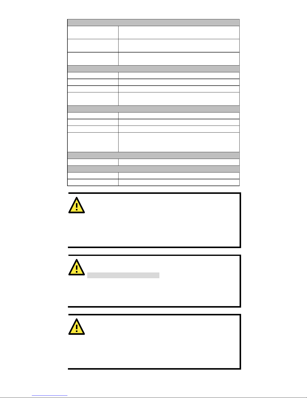
Specifications
Cellular Specification
Standards
GSM/GPRS/EDGE/UMTS/HSPA/LTE
Band Options OnCell G3150A-LTE-EU:
• B1 (2100 MHz)/B3 (1800 MHz)/B7 (2600
MHz)/B8 (900 MHz)/B20 (800 MHz)
• UMTS/HSPA 2100/1900/850/800/900 MHz
OnCell G3150A-LTE-US:
• B2 (1900 MHz)/B4 (AWS)/B5 (850 MHz)/
B13 (700 MHz)/B17 (700 MHz)/B25 (1900
MHz)
• UMTS/HSPA 2100/1900/AWS/850/900 MHz
• Universal quad-band
GSM/GPRS/EDGE/1800/1900 MHz
LTE Data Rate Category 3
Downlink: 100 Mbps (20 MHz bandwidth), 50 Mbps
(10 MHz bandwidth)
Uplink: 50 Mbps (20 MHz bandwidth), 25 Mbps (10
MHz bandwidth)
HSPA Data Rate
Downlink: Up to 42 Mbps (category 24)
Uplink: Up to 5.76 Mbps (category 6)
GPRS Data Rate
Downlink/Uplink: 85.6 kbps DL, 42.8 kbps UL
Page 13

- 13 -
Interface
Cellular Antenna
Connectors
2 SMA (female), MIMO for LTE, antenna diversity
for WCDMA
SIM Slots
Dual SIM card support, full-sized SIM (1FF)
GNSS
1 SMA (female), GPS: 1575.42 MHz, GLONASS:
1602 MHz
Ethernet
1, 10/100 Mbps auto negotiation speed, F/H duplex
mode and auto MDI/MDI-X connection (RJ45-type)
Serial Console Port
1, RS-232 (RJ45-type)
Serial Port 1, RS-232, RS-485-4W , RS-485-2W,
RS-422 (DB9 male)
Serial
Communication
Parameters
Data Bits: 5,6,7,8
Stop Bits: 1,1.5, 2 (when parity = None)
Parity: None, Even, Odd, Space, Mark
Baudrate: 75 bps to 921.6 kbps
LED Indicators
PWR1, PWR2, READY, FAULT, CELLULAR SIGNAL,
SIM1, SIM2, 2G/3G, 4G, GPS, TX/RX
Alarm Contact
1 relay output with current carrying capacity of 1 A
@ 24 VDC
Digital Inputs 2 electrically isolated inputs
+13 to +30 V for state “1”
+3 to -30 V for state “0”
Max. input current: 8 mA
Ground Screw
M5
Reset Button
Power reset/factory default reset
Software Specification
Network Protocol
ICMP, TCP/IP, UDP, DHCP, Telnet, DNS, SNMP,
HTTP, HTTPS, SMTP, SNTP, ARP
Routing/Firewall
NAT, port forwarding, IP/MAC/port filtering
VPN Max. Tunnel Number: 5 (Responder/Initiator)
IPsec (DES, 3DES, AES, MD5, SHA-1, DH2, DH5),
PSK/X.509/RSA
GRE over IPsec
Open VPN
NAT-T, PFS, DPD
Management
Options
Remote SMS Control, SNMPv1/v2c/v3,
Web/Telnet/Serial Console
Others
DDNS
Software Specifications (Moxa Proprietary)
GuaranLink Dual SIM 4-tiers heart-beat for reliable and
persistent cellular connectivity
OnCell Central
Manager
Large scale centralized device management over
private cellular IP addresses
Search Utility
Simple device configuration and management
utility
Physical Characteristics
Housing
Aluminum, providing IP30 protection
Mounting
DIN rail (default) or wall mount (optional)
Weight
492 g (1.08 lb)
Dimensions
126 x 30 x 107.5 mm (4.96 x 1.18 x 4.23 in)
Installation
DIN-rail mounting, wall mounting (with optional
kit)
Page 14
- 14 -
Environmental Limits
Operating
Temperature
Standard Models: 0 to 55°C (32 to 131°F)
Wide Temp. Models: -30 to 70°C (-22 to 158°F)
Storage
Temperature
-40 to 85°C (-40 to 185°F)
Ambient Relative
Humidity
5 to 95% (30°C, non-condensing)
Power Requirements
Input Voltage
12 to 48 VDC, redundant dual DC power inputs
Connector
4-pin removable terminal block
Power Consumption
9.6 W (12 V/0.78 A to 48 V/0.2 A)
Reverse Polarity
Protection
Present
Standards and Certifications
Safety
OnCell G3150A-LTE-US: UL 60950-1
EMI
OnCell G3150A-LTE-US: FCC Part 15 Subpart B
EMS
OnCell G3150A-LTE-EU: EN 61000-6-2/-4
Radio
OnCell G3150A-LTE-US: FCC ID N7NMC7355
OnCell G3150A-LTE-EU: EN 301 489-1,
EN 301 489-7, EN 301 511/4
Reliability
MTBF
> 528,596 hours
Warranty
Warranty Period
5 years
Details
See www.moxa.com/support/warranty.aspx
ATTENTION
The OnCell
G3150A-LTE is NOT a portable mobile device and
should be located at least
20 cm away from the human body.
The OnCell
G3150A-LTE is NOT designed for the general public.
A
well
-trained technician is required to deploy the OnCell
G3150A-LTE units and safely establish a wireless network.
ATTENTION
Use the antennas correctly!
Wide
-band (2G/3G/4G) antennas are needed when the OnCell
G3150A
-LTE
operates. Make sure that your antenna installation
is within a safety area, which is covered by a
lightning
protection or surge arrest system.
ATTENTION
This device complies with part 15 of the FCC Rules. Operation is
subject to the following two conditions:
1. This device may not cause harmful interference
2. This device
must accept any interference received, including
interference that may cause undesired operation.
Page 15

- 15 -
ATTENTION
Do not locate the antenna near overhead power lines or other
electric light or power circuits, or where it can come into contact
with such circuits. When installing the antenna, take extreme
care not to come into contact with such circuits, because they
may cause serious injury or death
when there is a surge. For
instructions on
proper installation and grounding of t
he antenna,
refer to national and local codes (for example, U.S.:
NFPA 70,
National Electrical Code,
Article 810, and Canada: Canadian
Electrical Code, Section 54).
ATTENTION
For EXPLOSION
-PROOF applications, the OnCell G3150A-LTE is
designed and certified to meet ATEX and IECEx requirements.
You should mount the device in a suitable enclosure rated at least
IP54
, in accordance with IEC/EN 60079-15 standard, so
that it is
accessible only by the use of a tool. The device is not intended for
use in an area
with pollution degree rating >
2 in accordance with
EN 60664
-1.
When
you install the OnCell G3150A-LTE in an enclosure, the
antennas must also be installed in such a way that they are inside
the enclosure. External antenna deployment is allowed only if the
antennas are certified
for ATEX Zone 2 use or confirm to IECEx
standards.
WARNING
EXPLOSION HAZARD!
Do not disconnect equipment unless you have
removed the
power source to the equipment or the area is known to be
non-hazardous.
ATEX Zone 2 Certification Information
Demko 16 ATEX 1812X
II 3 G Ex nA IIC T5 Gc
Ambient Range:
-30°C ≦Tamb≦+70°C
IECEx UL 16.0166X
Hazardous Location Standards
EN 60079-0:2012+A11:2013 / IEC 60079-0 6th Edition
EN 60079-15: 2010 / IEC 60079-15 4th Edition
Input Terminal Block Information
Input Terminal Block (J3) is suitable for 12-28 AWG (3.31-0.0804 mm2)
wire size, torque value 4.5 lb-in (0.51 Nm).
Page 16

- 16 -
Grounding-Wire Size
The minimum cross-sectional area of the grounding conductor should be
equal to that of the input cable.
Moxa Inc.
4
th
Floor, No.135, Lane 235, Baoqiao Rd. Xindian Dist., New Taipei City,
Taiwan
 Loading...