

Moxa Technologies OnCell G3100, OnCell G3110, OnCell G3150, OnCell G3150-HSPA, OnCell G3110-HSPA User Manual
Page 1

OnCell G3100 Series User’s Manual
Sixth Edition, September 2010
www.moxa.com/product
© 2010 Moxa Inc. All rights reserved.
Reproduction without permission is prohibited.
Page 2

OOnCell G3100 Series User’s Manual
The software described in this manual is furnished under a license agreement and may be used only in accordance with
the terms of that agreement.
Copyright Notice
Copyright ©2010 Moxa Inc.
All rights reserved.
Reproduction without permission is prohibited.
Trademarks
The MOXA logo is a registered trademark of Moxa Inc.
All other trademarks or registered marks in this manual belong to their respective manufact urers.
Disclaimer
Information in this document is subject to change without notice and does not represent a commitment on the part of
Moxa.
Moxa provides this document as is, without warranty of any kind, either expressed or implied, including, but not limited
to, its particular purpose. Moxa reserves the right to make improvements and/or changes to this manual, or to the
products and/or the programs described in this manual, at any time.
Information provided in this manual is intended to be accurate and reliable. However, Moxa assumes no responsibility for
its use, or for any infringements on the rights of third parties that may result from its use.
This product might include unintentional technical or typographical errors. Changes are periodically made to the
information herein to correct such errors, and these changes are incorporated into new editions of the publication.
Technical Support Contact Information
www.moxa.com/support
Moxa Americas
Toll-free: 1-888-669-2872
Tel: +1-714-528-6777
Fax: +1-714-528-6778
Moxa China (Shanghai office)
Toll-free: 800-820-5036
Tel: +86-21-5258-9955
Fax: +86-21-5258-5505
Moxa Europe
Tel: +49-89-3 70 03 99-0
Fax: +49-89-3 70 03 99-99
Moxa Asia-Pacific
Tel: +886-2-8919-1230
Fax: +886-2-8919-1231
Page 3

Table of Contents
1. Introduction ...................................................................................................................................... 1-1
Overview ........................................................................................................................................... 1-2
Package Checklist ............................................................................................................................... 1-2
Product Features ................................................................................................................................ 1-3
Product Specifications ......................................................................................................................... 1-3
2. Getting Started ................................................................................................................................. 2-1
Panel Layout ...................................................................................................................................... 2-2
Connecting the Hardware .................................................................................................................... 2-3
Wiring Requirements ................................................................................................................... 2-4
SIM Card Installation ................................................................................................................... 2-4
Connecting the Power .................................................................................................................. 2-5
Connecting the I/O Port ............................................................................................................... 2-5
Connecting to the Network ........................................................................................................... 2-6
Connecting to a Serial Device ....................................................................................................... 2-6
Connecting to the Ethernet Device ................................................................................................. 2-6
Adjustable Pull High/Low Resistors for the RS-485 Port (for RS-232/422/485 models) ......................... 2-6
LED Indicators ............................................................................................................................ 2-8
Reset Button ............................................................................................................................... 2-9
3. Initial IP Address Configuration ........................................................................................................ 3-1
Static and Dynamic IP Addresses .......................................................................................................... 3-2
Factory Default IP Address ................................................................................................................... 3-2
Configuration Options .......................................................................................................................... 3-2
OnCell Search Utility .................................................................................................................... 3-2
Web Console ............................................................................................................................... 3-2
ARP ........................................................................................................................................... 3-2
Telnet Console ............................................................................................................................ 3-3
Serial Console ............................................................................................................................. 3-7
4. Introducing Serial Port Operation Modes .......................................................................................... 4-1
Overview ........................................................................................................................................... 4-2
Device Control Applications .................................................................................................................. 4-2
Real COM and Secure Real COM Modes .......................................................................................... 4-2
Types of Real COM Connection ...................................................................................................... 4-3
Reverse Real COM and Secure Reverse Real COM Modes .................................................................. 4-4
Types of Reverse Real COM Connection .......................................................................................... 4-4
RFC 2217 Mode ........................................................................................................................... 4-5
Socket Applications ............................................................................................................................. 4-5
TCP Server and Secure TCP Server Modes ...................................................................................... 4-5
Types of TCP Server Connection .................................................................................................... 4-6
TCP Client and Secure TCP Client Modes ......................................................................................... 4-7
Types of TCP Client Connection ..................................................................................................... 4-7
UDP Mode .................................................................................................................................. 4-8
Types of UDP Connection .............................................................................................................. 4-8
Ethernet Modem Mode ......................................................................................................................... 4-9
SMS Tunnel Mode ............................................................................................................................... 4-9
Disabled Mode .................................................................................................................................... 4-9
5. Introducing OnCell Central and Ethernet Operation Modes ............................................................... 5-1
OnCell Central Management Software ................................................................................................... 5-2
OnCell Central Serial Device Connection ......................................................................................... 5-2
OnCell Central Ethernet Device Connection ..................................................................................... 5-3
Cellular-Enabling Ethernet Device ......................................................................................................... 5-3
Virtual Modem Mode ........................................................................................................................... 5-4
6. Using the Web Console ...................................................................................................................... 6-1
Using Your Web Browser...................................................................................................................... 6-2
Browser Cookie Settings............................................................................................................... 6-2
Trusted Site Settings ................................................................................................................... 6-3
Opening the Web Console ............................................................................................................. 6-4
Web Console Navigation ...................................................................................................................... 6-5
Basic Settings .................................................................................................................................... 6-5
Server Settings ........................................................................................................................... 6-6
Time Settings ............................................................................................................................. 6-6
Network Settings ................................................................................................................................ 6-7
Basic Network Settings ................................................................................................................ 6-7
DNS Settings .............................................................................................................................. 6-9
Advanced Network Settings .......................................................................................................... 6-9
Auto IP Report Settings .............................................................................................................. 6-10
Page 4

GuaranLink Settings (Pending) ........................................................................................................... 6-11
Overview .................................................................................................................................. 6-11
Background .............................................................................................................................. 6-11
Common Settings ...................................................................................................................... 6-12
GuaranLink Check Settings ......................................................................................................... 6-12
7. Cellular Network Settings ................................................................................................................. 7-1
GSM GPRS Settings (For OnCell G3110 and G3150) ................................................................................ 7-2
Cellular Setting (OnCell G3110-HSDPA and OnCell G3150-HSDPA) ........................................................... 7-2
Cellular Setting (OnCell G3110-HSDPA-JPS, OnCell G3150-HSDPA-JPS, OnCell G3110-HSDPA-JPN, OnCell
G3150-HSDPA-JPN) ............................................................................................................................ 7-3
GSM or GSM (CSD) Operation Mode .............................................................................................. 7-4
GPRS or GPRS/EDGE/UMTS/HSDPA Operation Mode ........................................................................ 7-5
SMS Operation mode ................................................................................................................... 7-6
Virtual Modem Operation mode ..................................................................................................... 7-6
8. Configuring Serial Port Operation Modes .......................................................................................... 8-1
Port Setting Basics .............................................................................................................................. 8-2
Device Control Applications .................................................................................................................. 8-2
Real COM Mode ........................................................................................................................... 8-2
Reverse Real COM Mode ............................................................................................................... 8-5
RFC2217 Mode ............................................................................................................................ 8-7
Socket Applications ............................................................................................................................. 8-9
TCP Server Mode ......................................................................................................................... 8-9
TCP Client Mode ........................................................................................................................ 8-11
UDP Mode ................................................................................................................................ 8-14
Ethernet Modem Mode ....................................................................................................................... 8-15
SMS Tunnel Mode ............................................................................................................................. 8-18
Disabled Mode .................................................................................................................................. 8-20
9. Configuring the Cellular-Enabling Ethernet Device ............................................................................ 9-1
Host to OnCell via Cellular ................................................................................................................... 9-2
OnCell to Host via Cellular ................................................................................................................... 9-2
10. Configuring Virtual Modem Mode .................................................................................................... 10-1
OnCell G3100 Web Settings ............................................................................................................... 10-2
Install Windows Driver Manager .................................................................................................. 10-2
Using OnCell Windows Driver Manager ......................................................................................... 10-4
Using PComm for Data Transmission ............................................................................................ 10-6
CSD via AT command ........................................................................................................................ 10-7
SMS via AT command........................................................................................................................ 10-8
GPRS via AT command ...................................................................................................................... 10-9
GPRS via Windows Dial-up Network .................................................................................................... 10-9
11. Understanding and Configuring a VPN ............................................................................................ 11-1
What Are VPNs? ............................................................................................................................... 11-2
OnCell VPN Specifications .................................................................................................................. 11-2
OnCell VPN Web Console Settings ....................................................................................................... 11-3
Manual Key/ESP ............................................................................................................................... 11-3
Configuration ............................................................................................................................ 11-3
Remote Network ....................................................................................................................... 11-3
Local Network ........................................................................................................................... 11-3
Incoming Security Settings ......................................................................................................... 11-4
Outgoing Security Settings ......................................................................................................... 11-4
ISAKMP/PSK .................................................................................................................................... 11-5
Configuration ............................................................................................................................ 11-5
Remote Network ....................................................................................................................... 11-5
ISAKMP (Key Management) ........................................................................................................ 11-6
Local Identity ............................................................................................................................ 11-6
ISAKMP phase 1 ........................................................................................................................ 11-6
ISAKMP phase 2 ........................................................................................................................ 11-6
Advanced settings ..................................................................................................................... 11-6
VPN system log events and error codes ............................................................................................... 11-7
12. Configuring OnCell Central Management Software .......................................................................... 12-1
Step 1: Server Settings ..................................................................................................................... 12-2
System Requirements ................................................................................................................ 12-2
Installing OnCell Central Manager ................................................................................................ 12-2
Using OnCell Central Manager ..................................................................................................... 12-6
Step 2: OnCell Device Web Console Settings ...................................................................................... 12-11
OnCell Central Settings ............................................................................................................ 12-11
OnCell Central Server .............................................................................................................. 12-12
Service Forwarding .................................................................................................................. 12-13
Step 3: Host Settings and Management ............................................................................................. 12-13
OnCell Central Web Console ...................................................................................................... 12-18
Page 5

Server ........................................................................................................................................... 12-19
Overview ................................................................................................................................ 12-19
Control Ports/User Ports info. .................................................................................................... 12-20
Account Settings ..................................................................................................................... 12-20
Device ........................................................................................................................................... 12-21
All Devices ............................................................................................................................. 12-21
All User Ports .......................................................................................................................... 12-22
Service Forwarding .................................................................................................................. 12-23
Device’s Settings and Maintenance ............................................................................................ 12-24
Overview ................................................................................................................................ 12-24
User Ports .............................................................................................................................. 12-25
Service Forwarding .................................................................................................................. 12-26
Maintenance ........................................................................................................................... 12-27
Logout .......................................................................................................................................... 12-28
13. Additional Serial Port Settings ........................................................................................................ 13-1
Port Communication Parameters ......................................................................................................... 13-2
Serial Parameters ............................................................................................................................. 13-2
Port Data Buffering/Log ..................................................................................................................... 13-3
Port Chipher Settings ........................................................................................................................ 13-3
14. System Management Settings ......................................................................................................... 14-1
Misc. Network Settings ...................................................................................................................... 14-2
Accessible IP List ....................................................................................................................... 14-2
SNMP Agent Settings ................................................................................................................. 14-3
DDNS ...................................................................................................................................... 14-4
Host Table ................................................................................................................................ 14-4
System Log Settings .................................................................................................................. 14-5
Virtual Server Settings ............................................................................................................... 14-5
Auto Warning Settings ....................................................................................................................... 14-6
Event Settings .......................................................................................................................... 14-6
Serial Event Settings ................................................................................................................. 14-7
E-mail Alert .............................................................................................................................. 14-8
SNMP Trap ................................................................................................................................ 14-9
SMS Alert ................................................................................................................................. 14-9
Maintenance .................................................................................................................................. 14-10
Console Setting ....................................................................................................................... 14-10
Ping ....................................................................................................................................... 14-10
Firmware Upgrade ................................................................................................................... 14-11
Configuration Import/Export ..................................................................................................... 14-11
Load Factory Defaults .............................................................................................................. 14-12
Change Password .................................................................................................................... 14-13
Certificate ...................................................................................................................................... 14-14
Ethernet SSL Certificate Import ................................................................................................. 14-14
Certificate/Key Delete .............................................................................................................. 14-14
System Monitoring .......................................................................................................................... 14-15
Serial to Network Connections .................................................................................................. 14-15
Serial Port Status .................................................................................................................... 14-15
Serial Port Error Count ............................................................................................................. 14-16
Serial Port Settings .................................................................................................................. 14-16
Chipher Usage Status .............................................................................................................. 14-17
System Status ................................................................................................................................ 14-17
Serial Data Log ....................................................................................................................... 14-17
System Log ............................................................................................................................ 14-18
Dout State .............................................................................................................................. 14-18
DIN and Power Status .............................................................................................................. 14-19
Network Status .............................................................................................................................. 14-19
Network Connections ............................................................................................................... 14-19
Network Statistics ................................................................................................................... 14-20
Routing .................................................................................................................................. 14-20
DHCP Client List ...................................................................................................................... 14-21
Internet Sessions List .............................................................................................................. 14-21
Save Configuration ......................................................................................................................... 14-22
Restart .......................................................................................................................................... 14-22
Restart System ....................................................................................................................... 14-22
Restart Ports ........................................................................................................................... 14-23
15. Software Installation/Configuration ............................................................................................... 15-1
Overview ......................................................................................................................................... 15-2
OnCell Windows Driver Manager ......................................................................................................... 15-2
Installing OnCell Windows Driver Manager .................................................................................... 15-2
Using OnCell Windows Driver Manager ......................................................................................... 15-4
Page 6

OnCell Search Utility ....................................................................................................................... 15-14
Installing OnCell Search Utility .................................................................................................. 15-14
Configuring OnCell Search Utility ............................................................................................... 15-16
Moxa OnCell Linux Real TTY Driver.................................................................................................... 15-20
Basic Procedure ...................................................................................................................... 15-20
Hardware Setup ...................................................................................................................... 15-20
Installing Linux Real TTY Driver Files .......................................................................................... 15-20
Mapping TTY Ports ................................................................................................................... 15-21
Removing Mapped TTY Ports ..................................................................................................... 15-21
Removing Linux Driver Files ...................................................................................................... 15-22
Moxa OnCell UNIX Fixed TTY Driver .................................................................................................. 15-22
Installing the UNIX Driver......................................................................................................... 15-22
Configuring the UNIX Driver ..................................................................................................... 15-23
A. Pinouts and Cable Wiring .................................................................................................................. A-1
Port Pinout Diagrams .......................................................................................................................... A-2
RS-232 (male DB9) Pinouts .......................................................................................................... A-2
4W/2W RS-485/RS-422 (Terminal Block) Pinouts ............................................................................ A-2
Power Input and Relay Output Pinouts ........................................................................................... A-2
Cable Wiring Diagrams ........................................................................................................................ A-3
Serial Cables .............................................................................................................................. A-3
Pin Assignments for DB9 and DB25 Connectors ............................................................................... A-3
B. RFC2217 ............................................................................................................................................ B-1
C. Dynamic Domain Name Server .......................................................................................................... C-1
Overview ........................................................................................................................................... C-1
Configuration ..................................................................................................................................... C-2
D. Well Known Port Numbers ................................................................................................................ D-1
E. Auto IP Report Protocol .................................................................................................................... E-1
F. GSM Alphabet .................................................................................................................................... F-1
G. Default Settings ................................................................................................................................ G-1
Page 7

1
1. Introduction
The OnCell G3100 series of cellular IP gateways have many exceptional features. There are currently eight
models in the OnCell G3100 series of IP gateways: the OnCell G3110, OnCell G3150, OnCell G3110-HSDPA,
OnCell G3150-HSDPA, OnCell G3110-HSDPA-JPS, OnCell G3150-HSDPA-JPS, OnCell G3110-HSDPA-JPN, and
OnCell G3150-HSDPA-JPN The main differences between the models are the seri al interface type s. Cellular IP
gateways give you an easy way to connect your serial and Ethernet devices to cellular mobi le networks.
The following topics are covered in this chapter:
Overview
Package Checklist
Product Features
Product Specifications
Page 8

OnCell G3100 Series Introduction
1-2
Overview
The OnCell G3100, which can be used to connect any serial device and Ethernet device to a cellular network,
supports a number of different operation modes. The OnCell COM driver turns the OnCell G3100’s serial ports
into virtual COM ports that allow you to communicate with your serial and Ethernet devices remotely over the
cellular network. The OnCell G3100 comes pre-installed with the TCP/IP protocol suite to transmit data back
and forth between the serial and Ethernet device and GPRS/EDGE or UMTS/HSDPA TCP/IP network.
The OnCell G3100 functions as a router to achieve Ethernet to cellular connectivity. All Ethernet devices
connected to the OnCell’s LAN port are hidden from public view via the OnCell’s NAT function.
The OnCell G3100 also supports Secure TCP Server, Secure TCP Client, Secure Real COM, and Secure Reverse
Real COM modes for security critical applications, such as access control, and remote site management.
The OnCell G3100 also comes with a built-in relay output that can be configured to indicate the priority of
events when notifying or warning engineers in the field, and the two digital inputs allow you to connect basic
I/O devices, such as sensors, to the cellular network.
For some applications, serial data must be delivered reliably even if communication is disrupted. The OnCell
G3100 provides a powerful function to ensure that serial data is buffered in case of a communication failure.
When a communication failure occurs, the serial data is buffered in the OnCell G3100 until communication is
resumed, at which point the buffered data is sent to its destination.
Package Checklist
Each OnCell G3100 serial and Ethernet cellular IP gateway is shipped in a separate box with standard
accessories. In addition, several optional accessories can be ordered separately. When you receive your
shipment, please check the contents of the box carefully, and notify your Moxa sales representativ e if any of
the items are missing or appear to be damaged.
OnCell G3100 Series cellular IP gateways are shipped with the following items:
Standard Accessories
• Document & Software CD
• Rubber SMA antenna (OnCell G3100 model name: ANT-CQB-ASM-1, OnCell G3100-HSDPA model name:
ANT-WCDMA-ASM-1.5)
• Din-Rail Kit
• 5-pin terminal block (screw type)
• 10-pin terminal block (screw type)
• Product warranty statement
• Quick Installation Guide
Optional Accessories
• Power Adaptor: 1.2 A (or above) @ 12 V
• DC power supply
• Power jack to terminal block cable
• Quad-band GSM/GPRS/EDGE antennas for OnCell G3110/G3150 series
(impedance = 50 ohms):
ANT-CQB-AHSM-00-3m: Omni 0dBi/10cm, magnetic SMA antenna, 3 m
ANT-CQB-AHSM-03-3m: Omni 3dBi/25cm, magnetic SMA antenna, 3 m
ANT-CQB-AHSM-05-3m: Omni 5dBi/37cm, magnetic SMA antenna, 3 m
Page 9

OnCell G3100 Series Introduction
1-3
Product Features
All models in the OnCell G3100 series have the following features:
• Quad-band 900/1800, 850/1900 MHz GSM/GPRS/EDGE
• Tri-band UMTS/HSDPA 850/1900/2100 MHz (OnCell G3100-HSDPA only)
• Special design for Japan Softbank (JPS) or NTTDocomo (JPN) operator
• Versatile operation modes, including Real COM, Reverse Real COM, RFC2217, TCP Server, TCP Client, UDP,
Ethernet Modem, and SMS Tunnel
• AT command over Ethernet
• Private IP management software
• Port buffering function to prevent loss of serial data when communication is disrupted
• Secure data access modes including Secure Real COM, Secure Reverse Real COM, Secure TCP Client, and
Secure TCP Server
• Adjustable baudrate feature for easy configuration of custom baudrates
• Redundant DC power inputs
• LED indicators for status and signal level
• 2 digital inputs and 1 relay output
Product Specifications
Note: The OnCell G3100 series has several hardware revisions. Please check the follow ing table to
see which functions are supported by the various revisio ns.
For Ethernet to Cellular, re fer chapter 9 for details. For Virtual Modem Mode, refer chapter 10 for
details.
OnCell Central
Manager
Ethernet Device
<-> Cellular
Virtual Modem Mode
IP Gateway
OnCell G3110 Rev 1.2
9
– –
OnCell G3150 Rev 1.2
9
– –
OnCell G3110 Rev 2.0
9 9 9
OnCell G3150 Rev 2.0
9 9 9
OnCell G3110-HSDPA Rev 1.0
9 9
–
OnCell G3150-HSDPA Rev 1.0
9 9
–
OnCell
G3110/G3150
OnCell
G3110/G3150-HSDPA
OnCell
G3110/G3150-HSDPA-JPS/JPN
Hardware
CPU Moxa CPU, 192 MHz
RAM 16 MB
Flash ROM 4 MB
LAN Interface
Ethernet 10/100 Mbps, RJ45 connector
Protection Built-in 1.5 KV magnetic isolation
Cellular Interface
Standard
Compliance
GSM/GPRS/EDGE GSM/GPRS/EDGE
UMTS/HSDPA
UMTS/HSDPA
Band Selection Quad-band
850/900/1800/1900
MHz
Tri-band 850/1900/2100
MHz
Quad-band
850/900/1800/1900 MHz
2100 MHz
Page 10

OnCell G3100 Series Introduction
1-4
Tx Power 1 watt GSM1800/1900,
2 watt EGSM850/900
1 watt GSM1800,
2 watt GSM900,
0.25 watt UMTS/HSDPA,
0.5 watt EDGE900,
0.4 watt EDGE1800
0.25 watt UMTS/HSDPA
GPRS Multi-slot
class
12 10 -
GPRS Mobile
Station Class
Class B -
EDGE Multi-slot
class
12 10 -
EDGE Mobile
Station Class
Class B -
GPRS Coding
Schemes
CS1 to CS4 -
SIM Control 3V
Serial Interface
No. of Ports 1
ESD Protection 15 KV
Serial Standards G3110/G3110-HSDPA: RS-232 (DB9 male connector)
G3150/G3150-HSDPA: RS-232 (DB9 male connector), RS-422/485 (5-pin te rminal block
connector)
Serial Communication Parameters
Parity None, Even, Odd, Space, Mark
Data Bits 5, 6, 7, 8
Stop Bit(s) 1, 1.5, 2 (when parity = None)
Flow Control RTS/CTS, XON/XOFF
Speed 50 bps to 921.6 Kbps
Serial Signals
RS-232 TxD, RxD, RTS, CTS, DTR, DSR, DCD, GND
RS-422 Tx+, Tx-, Rx+, Rx-, GND
RS-485-4w Tx+, Tx-, Rx+, Rx-, GND
RS-485-2w Data+, Data-, GND
I/O Interface
Alarm Contact 1 relay output with current carrying capacity of 1A@24 VDC
Digital Input 2 inputs electrically isolated from the electronics
DIN OFF: 0 to 3.3 VDC,
DIN ON : 10 to 48 VDC (I1 to COM_1/I2 to COM_2)
Software Features
Network Protocols ICMP, TCP/IP, UDP, DHCP, Telnet, DNS, SNMP, HTTP, SMTP, HTTPS, SNTP, ARP, SSL
Operation Modes Real COM, Reverse Real COM, TCP Server, TCP Client, UDP, RFC2217, Ethernet Modem,
SMS Tunnel
Secure Operation
Modes
Secure Real COM, Secure Reverse Real COM, Secure TCP Client, Secure TCP Server
Configuration and
Management
Options
SNMP MIB-II, SNMP Private MIB, SNMPv1/v2c/v3, DDNS, IP Report, Web/Telnet/Serial
Console/SSH
Authentication Local user-name and password
Security Accessible IP list
Utilities Provided for Windows 95/98/ME, Windows NT, Windows
2000/XP/2003/Vista/Server-2008, Windows XP/2003/Vista/
Server-2008 x64 Edition
Page 11

OnCell G3100 Series Introduction
1-5
Windows Drivers Windows 95/98/ME,Windows NT, Windows
2000/XP/2003/Vista/Server 2008, Windows
XP/2003/Vista/Server 2008 x64 Edition
Fixed TTY Drivers SCO U nix, SCO OpenServer 5, SCO OpenServer 6, UnixWare 7, SVR4.2, QNX 4.25, QNX 6,
Solaris 10, FreeBSD 5, FreeBSD 6
Real TTY Drivers Linux kernels 2.2.x, 2.4.x, 2.6.x
Physical Characteristics
Input Voltage 12 to 48 VDC
Data Link 585 to 900 mA (peak) @ 12 V
Power EFT/Surge
Protection
2 KV
Environmental Limits
Operating
temperature
-30 to 55°C (-22 to 131°F), 5 to 95% RH
Storage
temperature
-40 to 75°C (-40 to 167°F)
Regulatory Approvals
EMC CE: EN55022 Class A/EN55024
FCC: FCC part 15 subpart B, Class A
Safety UL: UL60950
Warranty 5 years
Page 12

2
2. Getting Started
This chapter covers the hardware installation of the OnCell G3100. Software installation is covered in the next
chapter.
The following topics are covered in this chapter:
Panel Layout
Connecting the Hardware
¾ Wiring Requirements
¾ SIM Card Installation
¾ Connecting the Power
¾ Connecting the I/O Port
¾ Connecting to the Network
¾ Connecting to a Serial Device
¾ Connecting to the Ethernet Device
¾ Adjustable Pull High/Low Resistors for the RS-485 Port (for RS-232/422/485 models)
¾ LED Indicators
¾ Reset Button
Page 13

OnCell G3100 Series Getting Started
2-2
Panel Layout
Front View
OnCell
G3110/G3150
OnCell
G3110-HSDPA/
G3150-HSDPA
G3110-HSDPA-JPS/
G3150-HSDPA-JPS/
G3110-HSDPA-JPN/
G3150-HSDPA-JPN
Top View
Bottom Views
For RS-232 models For RS-232/422/485 models
SIGNAL
PWR 2
FAULT
GPRS
PWR 1
READY
GSM
Tx
Rx
Ethernet
SMA Bulkhead Jack
PWR 2/PWR 1DI 2/DI 1 Relay
RESET
RS-232
RS-232 RS-422/485
Page 14

OnCell G3100 Series Getting Started
2-3
Rear View
Side Views
Connecting the Hardware
This section describes how to connect the OnCell G3100 cellular IP gateway to a host PC or serial/Ethernet
devices for first time testing purposes. We cover topics such as: Wiring Requirements, SIM Installation,
DIN-Rail Mounting, Connecting the Power, Connecting to a Serial Device, Connecting to an Ethernet Device,
Adjustable Pull High/Low Resistors for the RS-485 Port, and LED Indicators.
DIN-rail Support
SIM card Cover
Left Side
Right Side
Page 15

OnCell G3100 Series Getting Started
2-4
Wiring Requirements
ATTENTION
Safety First!
Be sure to disconnect the power cord before installing and/or wiring your device. The OnCell G3100 should be
secured at one location.
Wiring Caution!
Calculate the maximum possible current in each power wire and common wire. Observe all electrical codes
dictating the maximum current allowable for each wire size. If the current goes above the maximum ratings,
the wiring could overheat, causing serious damage to your equipment.
Temperature Caution!
Be careful when handling the device. When plugged in, the device’s internal components generate heat, and
consequently the casing may feel hot to the touch.
You should also heed the following guidelin es:
• Use separate paths to route wiring for power and devices. If power wiring and device wiring paths must
cross, make sure the wires are perpendicular at the intersection point .
NOTE: Do not run si gnal or communi cation wiring and power wiri ng in the same wi re conduit. To
avoid interference, wires with different signal characteristics should be routed separately.
• Use the type of signal transmitted through a wire to determine which wires should be kept separate. The
rule of thumb is that wiring that shares similar electrical characteristics can be bundled together.
• Keep input wiring and output wiring separate.
• Where necessary, it is advisable to label the wiring to all devices in the system.
SIM Card Installation
In order to protect the SIM card, the SIM card slot is located inside the OnCell G3100’s casing. You will need to
unscrew and remove the outer SIM card cover before installing or removing the SIM card.
Follow these steps to remove or install the SIM card:
1. Re move the screw holding the outer SIM card cover.
2. Push the outer SIM card cover to the left to remove it.
3. Rotate it upwards to expose the SIM card slot.
(a) Remove the SIM card from the SIM card slot, or
(b) Insert the SIM card into the SIM card slot.
4. Reverse the above steps to replace the outer SIM card cover.
1
2
3
Page 16

OnCell G3100 Series Getting Started
2-5
ATTENTION
If the modem is in GSM/GPRS mode, SIGNAL LEDs will not be illuminated if the phone number or APN is
incorrect. Check the GSM LED if the SIM car d is installed correctly.
The GSM LEDs on the front panel provide a convenient way of checking if the SIM card is installed properly.
If the antenna is installed and the network is operating normally, then at least one of the three SIGNAL LEDs
should be illuminated at all times. If non e of the GSM and SIGNAL LEDs are illuminated, then the SIM card
may not be installed properly. This is because the PIN code is stored on the SIM card; if the PIN code cannot
be accessed, then the modem will not be accessible over the network.
Connecting the Power
The dual power inputs that connect to the 4-pin power terminal block (2 terminals per power input) can be used
to connect the OnCell G3100 to a variety of field power sources that support 12 to 48 VDC. After connecting the
power wire to the OnCell G3100’s terminal block, the “PWR” LED will glow a solid green color to i ndicate that the
system is ready.
Connecting the I/O Port
Six terminals on the terminal block are reserved for the I/O ports, with 2 terminals used for each input, and 2
terminals used for the output.
Digital Input
Digital ON and OFF determine which of th e 2 electrically isolated inputs are used:
• +13 to +30 V for state “1” (On)
• +3 to -30 V for state “0” (Off)
Power Inputs
Page 17

OnCell G3100 Series Getting Started
2-6
Digital Output: 1 relay output with current carrying capacity of 1A @ 24 VDC
Power Status Event Relay
Off No Open
On Yes Open
No Short
Connecting to the Network
Connect one end of the Ethernet cable to the OnCell G3100's 10/100M Ethernet port and the other end of the
cable to the Ethernet network.
If the cable is properly connected, the OnCell G3100 will indicate a valid connection to the Ethernet as follows:
• The Ethernet LED glows a solid green when connected to a 100 Mbps Ethernet network.
• The Ethernet LED glows a solid orange when connected to a 10 Mbps Eth ernet network.
• The Ethernet LED flashes when Ethernet pack ets are being transmitted or received.
Connecting to a Serial Device
The OnCell G3110/G3110-HSDPA/G3110-HSDPA-JPS/G3110-HSDPA-JPN supports one RS-232 port that
connects through a DB9 male connector on the bottom panel.
The OnCell G3150/G3150-HSDPA/G3110-HSDPA-JPS/G3110-HSDPA-JPN supports one RS-232 port that
connects through a DB9 male connector on the bottom panel, and one RS-422/RS-485-4w/RS-485-2w that
connects through a 5-pin terminal block on the bottom panel.
Connecting to the Ethernet Device
Connect one end of the Ethernet cable to the OnCell G3100's 10/100M Ethernet port and the other end of the
cable to the Ethernet device.
If the cable is properly connected, the OnCell G3100 will indicate a valid Ethernet connection as follows:
• The Ethernet LED glows a solid green when connected to a 100 Mbps Ethernet device.
• The Ethernet LED glows a solid orange when connected to a 10 Mbps Eth ernet device.
• The Ethernet LED flashes when Ethernet pack ets are being transmitted or received.
Adjustable Pull High/Low Resistors for the RS-485 Port (for
RS-232/422/485 models)
In some critical environments, you may need to add termination resistors to prevent the reflection of serial
signals. When using termination resistors, it is important to set the pull high/low resistors correctly so that the
electrical signal is not corrupted. Since a particular pull high/low resistor value cannot fit all environments, the
OnCell uses DIP switches to set the pull high/low resistor values for the serial port.
Digital Output
Digital Inputs
Page 18

OnCell G3100 Series Getting Started
2-7
• To set the termination resistor to 150 KΩ, make sure both of the assigned DIP switches are in the OFF
position. This is the default setting.
• To set the termination resistor to 1 KΩ, make sure both of the assigned DIP switches are in the ON
position.
ATTENTION
Do not use the 1 KΩ setting on the OnCell when using the RS-232 interface. Doing so will degrade the RS-232
signals and shorten the maximum allowed communication distance.
SW 1 2 3
Pull High Pull Low Terminator
ON 1 KΩ 1 KΩ 120 KΩ
OFF 150 KΩ 150 KΩ –
Page 19

OnCell G3100 Series Getting Started
2-8
LED Indicators
The LED indicators on the front panel of the OnCell G3100-HSDPA series are described in the following table.
LED Name LED Color LED Function
PWR Green DC Power is active.
off Power is off, or power error condition exists.
Tx Green The serial port is transmitting data
Off No data is being transmitted or received through the serial port
Rx Amber The serial port is receiving data.
off No data is being received through the serial port.
REG Amber Registered with cellular provider (only for –JPS/JPN model)
off SIM slot not in used (only for –JPS/JPN model)
GSM Amber GSM is connected.
off GSM is disconnected.
GRPS Amber GPRS is connected
off GPRS is disconnected.
UMTS Amber UMTS is connected .
off UMTS is disconnected.
HSDPA Amber HSDPA is connected.
off HSDPA is disconne cted.
Ready Green Steady on: Software Ready.
Blinking slowly (1 sec): The OnCell has been located by the OnCell
Search Utility.
off Power is off, or is booting up.
Fault Red Steady on: Booting up, or IP fault.
Blinking slowly (1 sec): Cannot get an IP address from the DHCP
server
off Power is off, or there is no error condition.
Signal (3 LEDs) Green Signal Level
(at least 2 LEDs must illuminated for data transmission)
ATTENTION
GSM LED:
OFF: Cannot register with cellular providers using GSM mode, due to the wrong PIN code, or no cellular
provider available. Signal LEDs will also be off.
ON: Registered with ce llular provider. Signal LEDs will be on.
GPRS LED
:
OFF: Cannot register with cellular providers using GPRS mode, due to wrong PIN code (GSM /signal LEDs
off), no cellular provider available (GSM/signal LEDs off), wrong APN (GSM on/signal LEDs off), or
wrong username/password (GSM on/signal LEDs off).
ON: Registered with ce llular provider using GPRS mode. GSM/Signal LEDs will be on.
UMTS/HSDPA LED:
OFF: Cannot register with cellular providers using UMTS/HSDPA mode due to the wrong PIN code (UMTS
or HSDPA/signal LEDs off), no cellular provider available (UMTS or HSDPA/signal LEDs off), wrong
APN (UMTS or HSDPA on/signal LEDs off), or wrong username/password (UMTS or HSDPA
on/signal LEDs off).
ON: Registered with ce llular provider using UMTS/HSDPA mode. UMTS or HSDPA/Signal LEDs will be
on.
Page 20

OnCell G3100 Series Getting Started
2-9
Reset Button
Press the Rest button continuously for 5 sec to load factory defaults: Use a pointed object, such as a
straightened paper clip or toothpick, to press the reset button. This will cause the Ready LED to blink on and off.
The factory defaults will be loaded once the Ready LED stops blinking (default IP: 192.168.127.254).
Page 21

3
3. Initial IP Address Configuration
When setting up the OnCell G3100 for the first time, the first thing you should do is configure its IP address.
This chapter introduces the different methods that can be used. Please refer to Chapter 13: System
Management Settings, for more details about network settings.
The following topics are covered in this chapter:
Static and Dynamic IP Addresses
Factory Default IP Address
Configuration Options
¾ OnCell Search Utility
¾ Web Console
¾ ARP
¾ Telnet Console
¾ Serial Console
Page 22

OnCell G3100 Series Initial IP Address Configuration
3-2
Static and Dynamic IP Addresses
Determine whether your OnCell G3100 needs to use a static IP address or dynamic IP address (either DHCP or
BOOTP application).
• If your OnCell G3100 is used in a static IP environment, you must assign a specific IP address usin g
one of the tools described in this chapter.
• If your OnCell G3100 is used in a dynamic IP environment, the IP address will be assigned
automatically from over the network. In th is case, set the IP configuration mode to DHCP or BO OTP.
ATTENTION
Consult your network administrator on how to reserve a fixed IP address for your OnCell G3100 in the MAC-IP
mapping table when using a DHCP Server or BOOTP Server. For most applications, you should assign a fixed
IP address to your OnCell G3100.
Factory Default IP Address
The OnCell G3100 is configured with the following default private IP address:
192.168.127.254
Note that IP addresses that begin with “192.168” are referred to as private IP addresses. Devices configured
with a private IP address are not directly accessible from a public network. For example, you would not be able
to ping a device with a private IP address from an outside Internet connection. If your application requires
sending data over a public network, such as the Internet, your OnCell G3100 will need a valid public IP address,
which can be leased from a local ISP.
Configuration Options
OnCell Search Utility
You may configure your OnCell G3100 with the bundled OnCell Search Utility for Windows. Please refer to
Chapter 14, Software Installation/Configuration, for details on how to install and use OnCell Search Utility.
Web Console
You may configure your OnCell G3100 using a standard web browser. Please refer toChapter 6, Using the Web
Console, for details on how to access and use the OnCell G3100 web console.
ARP
You may use the ARP (Address Resolution Protocol) command to set up an IP address for your OnCell G3100.
The ARP command tells your computer to associate the On Cell G3100’s MAC address with an IP address.
Afterwards, use Telnet to access the OnCell G3100 and its IP address will be reconfigured.
Page 23

OnCell G3100 Series Initial IP Address Configuration
3-3
ATTENTION
In order to use the ARP setup method, both your computer and the OnCell G3100 must be conne cted to th e
same LAN. You may use an Ethernet cable to connect the OnCell G3100 di rectly to your comp uter’s Ethernet
card. Before executing the ARP command, your OnCell G3100 must be configured with the factory default IP
address (192.168.127.254) and your computer and the OnCell G3100 must be on the same subnet. In
addition, note that ARP command must be issued within 3 min utes after the OnCell is turned. After 3 min utes
have elapsed, the OnCell will no longer accept ARP comma nds.
To use ARP to configure the IP address, complete the following:
1. Obtain a valid IP address for your OnCell G3100 from your network administrator.
2. Obtain your OnCell G3100’s MAC address from the label on the bottom panel.
3. Execute the arp -s command from your computer’s MS-DOS prompt as follows:
arp -s <IP address> <MAC address>
For example,
C:\> arp -s 192.168.200.100 00-90-E8-04-00-11
4. Next, execute a special Telnet command by entering the following exactly:
telnet 192.168.200.100 6000
When you enter this command, a Connect failed message will appear, as shown below.
5. After the OnCell G3100 reboots, its IP address will be assigned to the new address and you can reconnect
using Telnet to verify that the update was successful.
Telnet Console
Depending on how your computer and network are configured, you may find it convenient to use network
access to set up your OnCell G3100’s IP address. This can be done using Telnet.
ATTENTION
Figures in this section were taken from the OnCell G3100’s Telnet console.
1. From the Windows desktop, select Start Æ Run, and then type the following content in the Run window:
telnet 192.168.127.254
If your IP address is different from the default setting, use your IP address instead. Click OK.
Page 24

OnCell G3100 Series Initial IP Address Configuration
3-4
2. The console terminal type selection is displayed as shown. Enter 1 for ansi/vt100, and then press ENTER
to continue.
3. The following page will only appear if the OnCell G3100 is password protected. Enter the console password
if you are prompted to do so, and then press ENTER.
Page 25

OnCell G3100 Series Initial IP Address Configuration
3-5
4. Press N or use the arrow keys to select Network, and then press ENTER.
5. Press B or use the arrow keys to select Basic, and then press ENTER.
6. Use the arrow keys to move the cursor to IP address. Use the DELETE, BACKSPACE, or SPACE keys to
erase the current IP address, and then type in the new IP address and press ENTER. Note that if you are
using a dynamic IP configuration (BOOTP, DHCP, etc.), you will need to go to the IP configuration field
and press ENTER to select the appropriate configuration.
Page 26

OnCell G3100 Series Initial IP Address Configuration
3-6
7. Press ESC twice to return to the previous page. Press Y to confir m.
8. Press ESC to return to the previous page.
9. Press A or use the arrow keys to select Save and then press ENTER. Press ENTER again to confirm the
save command.
Page 27

OnCell G3100 Series Initial IP Address Configuration
3-7
10. Press R or use the arrow keys to select Restart and then press ENTER.
11. Press S or use the arrow keys to select System and then press ENTER to restart the OnCell G3100.
Serial Console
The OnCell G3100 supports configuration through the serial console, which is the same as the Telnet console
but accessed through the RS-232 console port rather than over the network. Once you have entered the serial
console, the configuration options and instructions are the same as if you were using the Telnet console.
The following instructions and screenshots show how to enter the serial console using PComm Terminal
Emulator, which is available free of charge as part of the PComm Lite suite. You may use a different terminal
emulator utility, although your actual screens and procedures may vary slightly from the following instructions.
1. Turn off the power to the OnCell G3100. Use a serial cable to connect the OnCell G3100’s serial console port
to your computer’s RS-232 serial port.
2. From the Windows desktop select Start Æ All Programs Æ PComm Lite Æ Terminal Emulator.
Page 28

OnCell G3100 Series Initial IP Address Configuration
3-8
3. The PCo mm Terminal Emulator window should appear. From the Port Manager menu, select Open, or
simply click the Open icon as shown below:
4. The Prop erty window opens automatically. Select the Communication Parameter tab, and then select
the appropriate COM port for the connection (COM4 in this example). Configure the parameters for 115200,
8, N, 1 (115200 for Baudrate, 8 for Data Bits, None for Parity, and 1 for Stop Bits).
5. From the Property window’s Terminal page, select ANSI or VT100 for Terminal Type and then click OK.
6. If you are using the OnCell G3100, you may power it up at this point and hold down the “grave accent key”
(`) while powering it up, as shown below. Note that the grave accent key (sometimes called “backwards
apostrophe”) is NOT the apostrophe key—it is the key usually found next to the number 1 key.
Page 29

OnCell G3100 Series Initial IP Address Configuration
3-9
7. If the OnCell G3100 has been set up for password protection, you will be prompted to enter the password.
After you enter the password, or if password protection was not enabled, you will be prompted to select the
terminal mode. Press 1 for ansi/vt100 and then press ENTER.
8. The main menu should appear. Once you are in the console, you may configure the IP address through the
Network menu item, just as with the Telnet console. Please refer to steps 4 to 11 in the Telnet Console
section to complete the initial IP configuration.
Page 30

4
4. Introducing Serial Port Operation Modes
In this chapter, we describe the various operation modes of the OnCell G3100. The OnCell G3100 modes are
grouped by type of application, such as Device Control. The options include an operation mode that reli es on a
driver installed on the host computer, and operation modes that rely on TCP/IP socket programming concepts.
After selecting the proper operation mode, please refer to Chapter 6: Using the Web Console, for detailed
information on configuration para meters.
The following topics are covered in this chapter:
Overview
Device Control Applications
¾ Real COM and Secure Real COM Modes
¾ Types of Real COM Connection
¾ Reverse Real COM and Secure Reverse Real COM Modes
¾ Types of Reverse Real COM Connection
¾ RFC 2217 Mode
Socket Applications
¾ TCP Server and Secure TCP Server Modes
¾ Types of TCP Server Connection
¾ TCP Client and Secure TCP Client Modes
¾ Types of TCP Client Connection
¾ UDP Mode
¾ Types of UDP Connection
Ethernet Modem Mode
SMS Tunnel Mode
Disabled Mode
Page 31

OnCell G3100 Series Introducing Serial Port Operation Modes
4-2
Overview
The OnCell G3100 IP gateway can cellular network-enable a serial device. OnCell G3100 IP gateway device is
assigned an IP address by your service provider (your “cellular ISP”). In addition, the OnCell G3100 IP gateway
can cellular network-enable Ethernet devices on the local Ethernet – see chapter 5 for details.
For Cellular-Enabling Serial Devices, The OnCell G3100 cellular IP gateway enables traditional serial
(RS-232/422/485) devices for transmitting data over the cellular network. The IP modem is a tiny computer
equipped with a CPU and TCP/IP protocols that can bi-directionally translate data between the serial and IP
formats. With the OnCell G3100, your computer will be able to access, manage, and configure remote facilities
and equipment over the cellular network from anywhere in the world.
Traditional SCADA and data collection systems rely on serial ports to collect data from various kinds of
instruments. Since the OnCell G3100 cellular IP gateway network-enables instruments equipped with an
RS-232, RS-422, or RS-485 communication port, your SCADA and data collection system will be able to access
all instruments connected to a standard TCP/IP network, regardless of whether the devices are used locally or
at a remote site.
The OnCell G3100 is an external IP-based network device that allows you to expand a serial port for a host
computer on demand. As long as your host computer supports the TCP/IP protocol, you will not be limited by
the host computer’s bus limitation (such as ISA or PCI), nor will you be limited if you do not have drivers for
various operating systems.
In addition to providing socket access, the OnCell G3100 also com es with a Real COM/TTY driver and a Reverse
Real COM/TTY driver that transmits all serial signals intact. This enables you to preserve your existing
COM/TTY-based software without needing to invest in additional software.
Three different socket modes are available: TCP Server, TCP Client, and UDP. The main difference between the
TCP and UDP protocols is that TCP guarantees delivery of data by requiring the recipient to send an
acknowledgement to the sender. UDP does not require this type of verification, making it possible to offer faster
delivery. UDP also allows you to unicast da ta to one IP, or multicast the data to a group of IP addresses.
The OnCell G3100 supports standard SSL secure data access for Real COM/TTY modes, Reverse Real COM/TTY
modes, TCP server mode, and TCP Client mode to protect data transmitted over the cellular network.
Device Control Applications
The OnCell G3100 offers the following modes for device control applications: Real COM/Secure Real COM,
Reverse Real COM/Secure Reverse Real COM, and RFC2217 modes.
Real COM and Secure Real COM Modes
The OnCell G3100 comes bundled with Moxa drivers for Windows 98/ME/NT/ 2000/XP/2003/2008/Vista
systems and TTY drivers for Linux and Unix systems. Real COM mode includes optional data encryption using
Page 32
OnCell G3100 Series Introducing Serial Port Operation Modes
4-3
SSL. (For Windows systems, this option is only supported for Windows 2000, XP x86/x64, 2003 x86/x64, Vi sta
x86/x64, and 2008 x86/x64.)
In Real COM mode, the bundled drivers are able to establish a transparent connection between a host and a
serial device by mapping the serial port on the OnCell G3100 to a local COM/TTY port on the host computer.
Real COM mode supports up to 2 simultaneous connections that enable 2 hosts to simultaneously collect data
from the same serial device.
One of the major conveniences of using Real COM mode is that it allows you to use software that was written
for pure serial communication applications. The OnCell COM driver intercepts data sent to the host’s COM port,
packs it into a TCP/IP packet, and then redirects it through the host’s Ethernet card to the Internet. At the other
end of the connection, the OnCell G3100 accepts the IP frame from the cellular network, unpacks the TCP/IP
packet, and then transparently sends the data through the serial port to the attached serial device.
Types of Real COM Connection
This section illustrates the types of RealCOM connections you can use, depending on the service you obtain
from your local cellular service provider.
Fixed Public IP for OnCell
If your cellular service provider offers a fixed public IP address after you connect to the cellular network, you
can access the OnCell G3100 via a host PC using either a private IP or public IP.
Utilize Auto IP report
If your cellular service provider offers a dynamic public IP address after you connect to the cellular network,
you can access the OnCell G3100 via a host PC using a fixed public IP. Sinc e the IP address of the OnCell G3100
is changed each time it is connected to the cellular network, the host IP can be notified of the change by an Auto
IP Report message sent from the OnCell G3100. Please refer to Appendix E to see the format of the Auto IP
Report Protocol.
Page 33
OnCell G3100 Series Introducing Serial Port Operation Modes
4-4
Domain name with DDNS
If your cellular service provider offers a public IP address after you connect to the cellular network, you can also
access the OnCell G3100 using the domain name. To do this, you will need to register with a DDNS service
provider and then enable the DDNS function in the OnCell G3100. Please refer to Appendix C for more
information.
Reverse Real COM and Secure Reverse Real COM Modes
The OnCell G3100 comes bundled with Moxa drivers for Windows 98/ME/NT/2000/XP/2003/2008/Vista
systems and TTY drivers for Linux and Unix systems. Reverse Real COM mode includes optional data encryption
using SSL. (For Windows systems, this option is only supported for Windows 2000, XP x86/x64, 2003 x86/x64,
Vista x86/x64, and 2008 x86/x64.)
Reverse Real COM mode uses a mechanism similar to port mapping to enable your remote device that is using
a private IP address to remain accessible to external hosts. When this mode is enabled, the Moxa driver that
comes with the device establishes a transparent connection from the device to the remote host by mapping the
device’s serial port to a local COM port on the remote host. Reverse Real COM mode supports up to 2
simultaneous connections that enable serial devices to send data to 2 hosts simultaneously.
Types of Reverse Real COM Connection
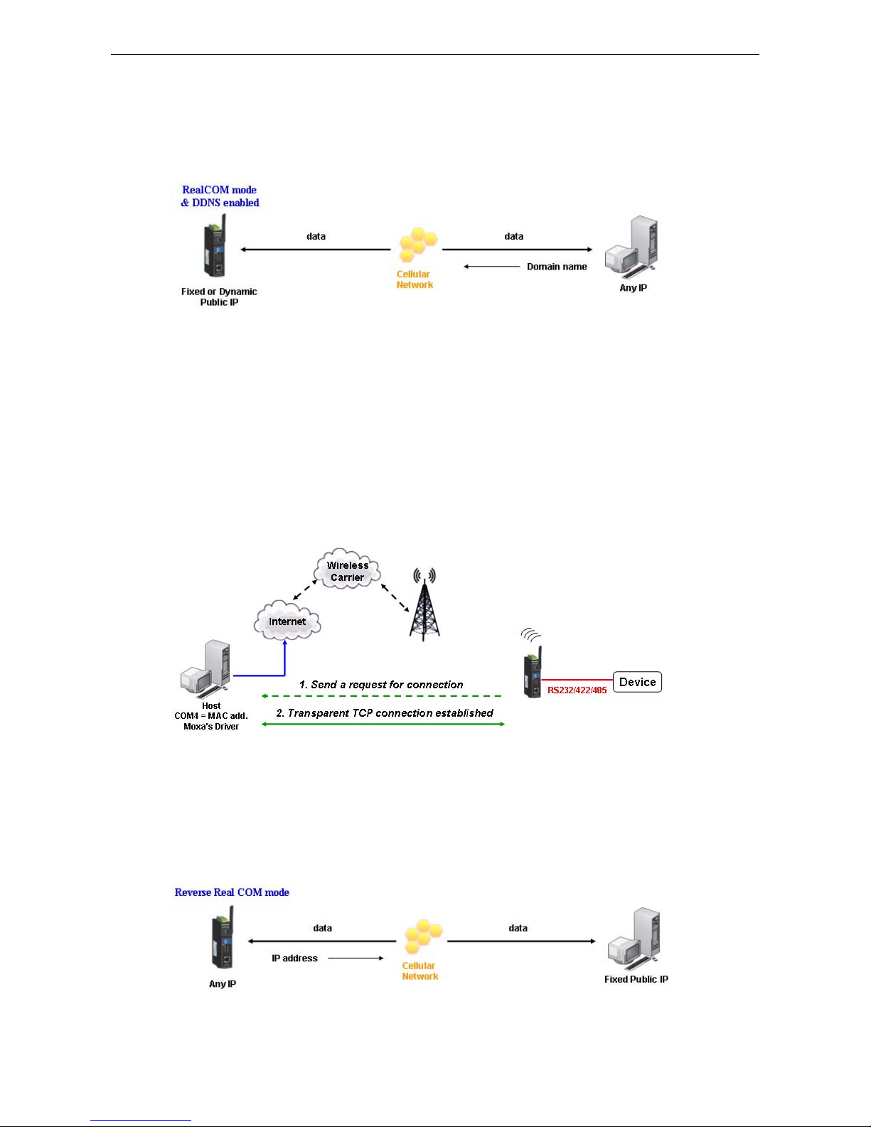
Reverse RealCOM to PC’s IP address
Most cellular service providers only provide customers with a dynamic private IP address, which m eans that the
OnCell G3100 will only obtain an IP address once it is connected to t he cellular network. Re verse RealCOM is a
great feature that allows a PC host to access an OnCell G3100 configured with private IP address.
Page 34
OnCell G3100 Series Introducing Serial Port Operation Modes
4-5
Reverse RealCOM to PC’s domain name
With Reverse RealCOM mode, you can connect to a PC host using the PC’s IP address. You can also connect to
your PC host with the PC’s domain name, if you have one. Please refer to Appendix C for more information.
RFC 2217 Mode
RFC-2217 mode is similar to Real COM mode in that a driver is used to establish a transparent connection
between a host computer and a serial device by mapping the serial port on the OnCell G3100 to a local COM
port on the host computer. RFC2217 defines general COM port control options based on the Telnet protocol.
Third party drivers supporting RFC-2217 are widely available on the Internet and can be used to implement
virtual COM mapping to your OnCell G3100’s serial port. Please refer to Appendix B for more information.
Socket Applications
The OnCell G3100 offers the following modes for socket applications: TCP Server and Secure TCP Server, TCP
Client and Secure TCP Client, and UDP.
TCP Server and Secure TCP Server Modes
In TCP Server mode, the serial port on the OnCell G3100 is assigned a port number. The host comput er initiates
contact with the OnCell G3100, establishes the connection, and receives data from the serial device. This
operation mode also supports up to 2 simultaneous connections, enabling multiple hosts to collect data from
the same serial device at the same time.
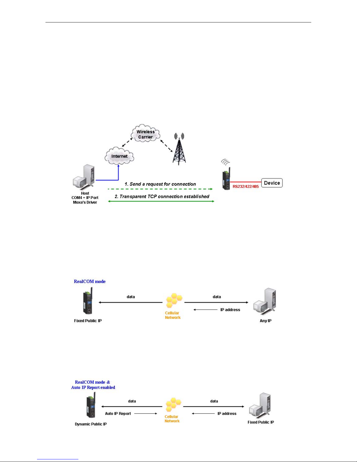
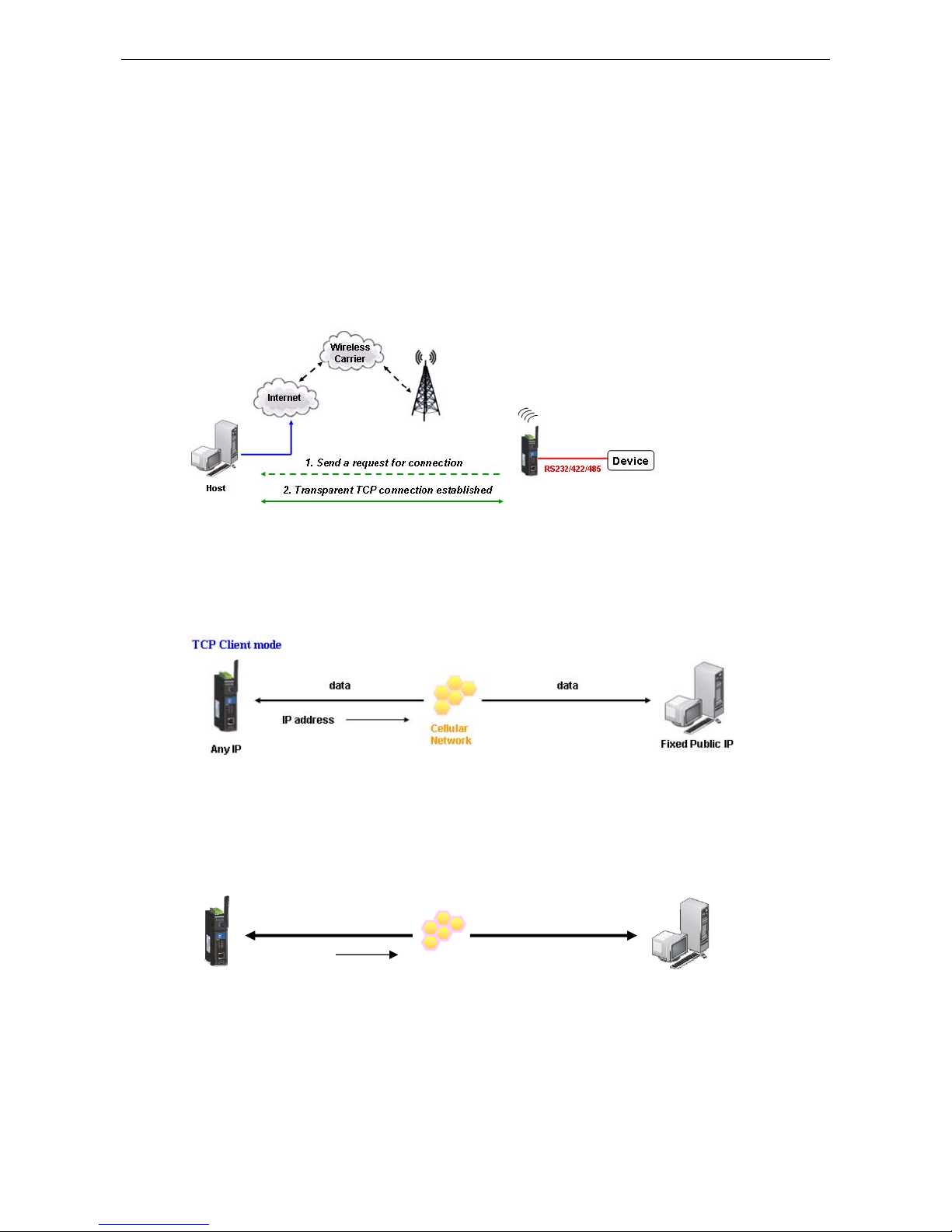
As illustrated in the figure, data transmission proceeds as follows: The host requests a connection from the
OnCell G3100, which is configured for TCP Server mode. Once the connection is established, data can be
transmitted in both directions between the host and the OnCell G3100.
TCP Server mode includes optional data encryption using SSL
Any IP
Cellular Network
Domain
name
Domain Name
Reverse RealCOM
Mode
Page 35
OnCell G3100 Series Introducing Serial Port Operation Modes
4-6
Types of TCP Server Connection
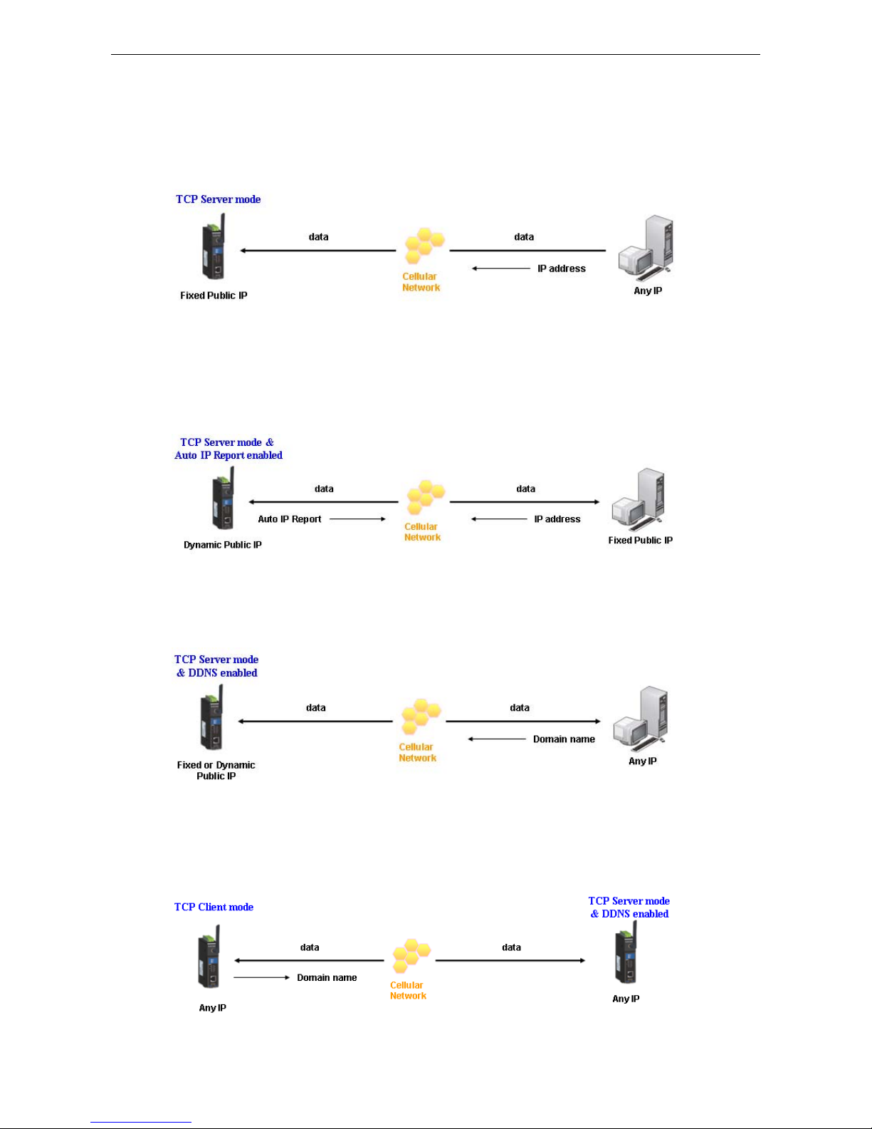
Fixed Public IP for the OnCell
If your cellular service provider offers a fixed public IP address after you connect to the cellular network, you
can access the OnCell G3100 from a host PC using either a private IP or public IP.
Using Auto IP report
If your cellular service provider offers a dynamic public IP address after you connect to the cellular network,
you can access the OnCell G3100 from a host PC using a fixed public IP. Since the IP address of the OnCell
G3100 is changed every time it is connected to the cellular ne twork, the host IP can be aware of the change by
the Auto IP Report message sent from the OnCell G3100. Please refer to Appendix E for the format of the Auto
IP Report Protocol.
Domain name with DDNS
If your cellular service provider offers a public IP address after you connect to the cellular network, you can also
use the domain name to access the OnCell G3100. You would need to register with a DDNS service provider and
then enable the DDNS function in the OnCell G3100. Please refer to Appendix C for more information.
Connecting TCP client and TCP server within the same cellular service provider
In order to connect properly, the IP addresses of the two OnCell devices must belong to the same subnetwork.
To ensure that this is the case, use the same cellular service provider to connect the devices to the network. In
addition, you will need to request that the cellular service provider provide you with two private IP addresses
(e.g., 192.168.1.1 and 192.168.1.2).
Page 36
OnCell G3100 Series Introducing Serial Port Operation Modes
4-7
TCP Client and Secure TCP Client Modes
In TCP Client mode, the OnCell G3100 can actively establish a TCP c onnection to a pre-defi ned host computer
when serial data arrives. After the data has been transferred, the OnCell G3100 c an automati cally dis connect
from the host computer by using the Inactivity time settings.
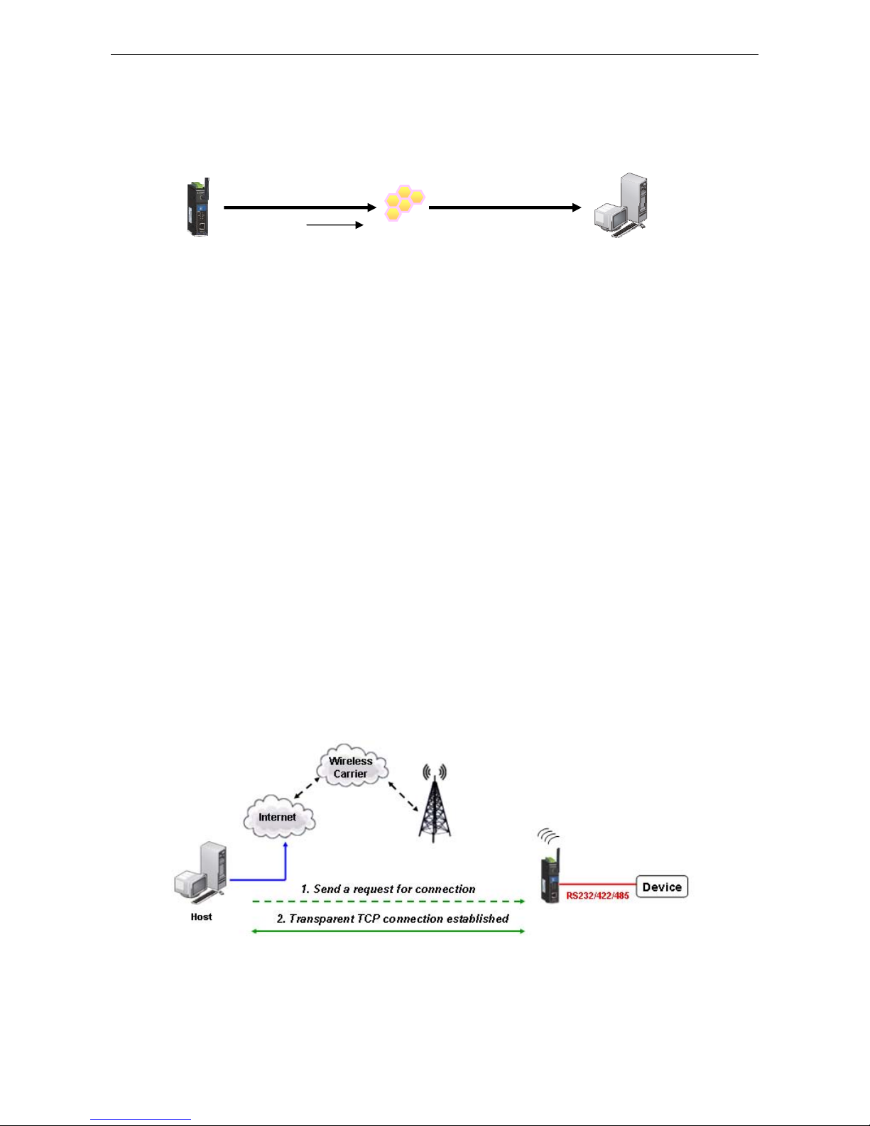
As illustrated in the figure below, data transmission proceeds as follows:
1. The OnCell G3100, configured for TCP Client mode, requests a connection to the host.
2. Once the connection is established, data can be transmitted in both directions between the host and the
OnCell G3100.
TCP Client mode includes optional data encryption using SSL.
Types of TCP Client Connection
TCP Client to PC’s IP address
The OnCell G3100 will only be able to connect to a host PC if the PC is using a public IP address.
TCP Client to PC’s domain name
To connect to a host PC, the host PC must be configured with public IP address. If it is using a dynamic public
IP, then the OnCell G3100 can connect to it using the host’s domain name. Please refer to Appendix C for more
information.
Connecting TCP client and TCP server within the same cellular service provider
In order to connect properly, the IP addresses of the two OnCell devices must belong to the same subnetwork.
To ensure that this is the case, use the same cellular service provider to connect the devices to the network. In
addition, you will need to request that the cellular service provider provide you with two private IP addresses
(e.g., 192.168.1.1 and 192.168.1.2).
Cellular Network
Domain name
Domain Name
TCP Client mode
Page 37
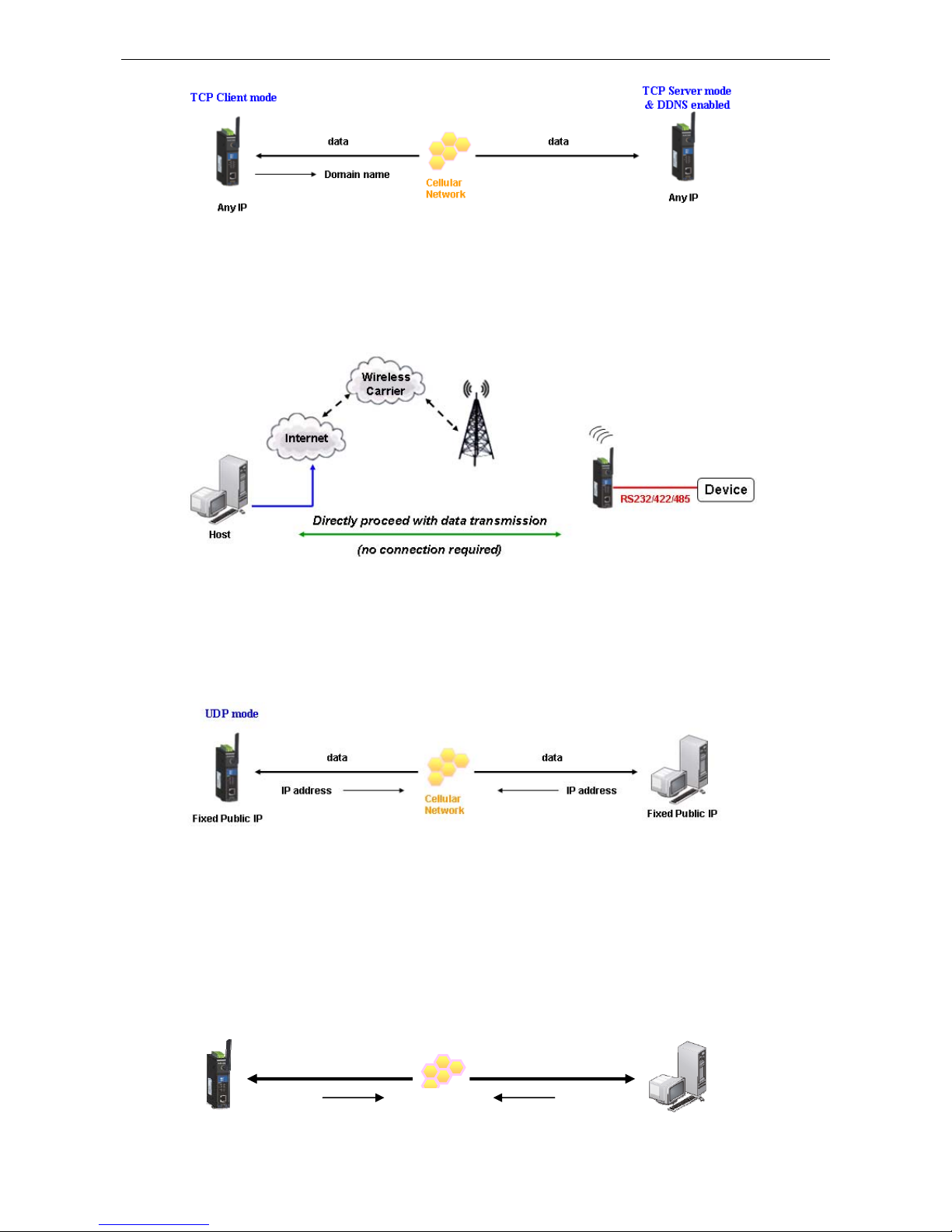
OnCell G3100 Series Introducing Serial Port Operation Modes
4-8
UDP Mode
Compared to TCP communicat ion, UD P is fast er and mo re efficient. In UDP mode, you can unicast to one host
or multicast to multiple hosts and the serial device can receive data from one or multiple host computers. These
traits make UDP mode especially well suited for message display applications.
Types of UDP Connection
Fixed Public IPs for both OnCell and Host PC
If your cellular service provider offers a fixed public IP address after you connect to the cellular network, you
can access the OnCell G3100 from a host PC that has a fixed public IP.
Domain name with DDNS
If your cellular service provider assigns a public IP address after you connect to the cellular network, you can
also access the OnCell G3100 using the domain name. If your service provider assigns a public IP address
(either fixed or dynamic) to your cellular device and your control center is the side that initiates the connection,
you can enable the DDNS function and UDP mode to allow other devices on the Internet to connect to your
device using its domain name. This will ensure that your device will remain reachable even when its public IP
address is updated. Note that you will need to register your device with a DDNS server. Please refer to
Appendix C for more information.
Fixed or Dynamic Public IP
UDP mode & DDNS enabled
Fixed or Dynamic Public IP
Page 38

OnCell G3100 Series Introducing Serial Port Operation Modes
4-9
Ethernet Modem Mode
Ethernet Modem mode is designed for use with legacy operating systems, su ch as MS-DOS, that do not support
TCP/IP networks. By connecting a properly configured OnCell G3100 serial port to the MS-DOS computer’s
serial port, it is possible to use legacy software to transmit data over the cellular network, even if the software
was originally designed to transmit data through a modem. In this case, the AT commands are converted into
IP format.
SMS Tunnel Mode
A major benefit of GSM technology is that it supports short messages (SMS) for easy communication over the
mobile network. Moxa’s proprietary SMS Tunnel Mode allows you to expand your applications and reduce cost.
For example, SMS Tunnel Mode can be used to update the message on a highway display panel, place refill
orders for vending machines, handle maintenance for remote rental equipment, or even help create an SMS
alarm by directly transforming text, binary, or unicode data from a legacy device to short messages. SMS
Tunnel Mode is particularly suitable for devices that communicate inf requently, or lack access to the local
network. SMS Tunnel Mode converts ASCII, binary code, and UCS2 data to short messages transparently (both
back and forth). In addition, the caller ID (phone number) identification can be used to block messages sent
from uncertified users, broadcast messages, and unwanted SMS advertisements.
Moxa’s proprietary SMS Tunnel Mode has the following features:
1. Transparently converts serial data to short message, and vise versa.
2. Text , binary, and Unicode formats are supported.
3. Verification of Incoming Caller ID calls is implemented to block uncertified users.
Disabled Mode
You can disable any port on the OnCell G3100 by setting the operation mode to Disabled.
Page 39

5
5. Introducing OnCell Central and Ethernet
Operation Modes
In this chapter, we introduce OnCell Central Management Software for host and device sites in the private IP
domain. We also describe the Ethernet operation modes of the OnCell G3100. The OnCell G3100 not only
connects serial devices to cellul ar networks, but Ethernet devices as well. After se lecting the proper operati on
mode, please refer to Chapters 9, 10, 11, and 14 for detailed information on configuration.
The following topics are covered in this chapter:
OnCell Central Manageme
nt Software
¾ OnCell Central Serial Device Connection
¾ OnCell Central Etherne
t
Device Connection
Cellular-Enabling Ethernet Device
Virtual Modem Mode
Page 40
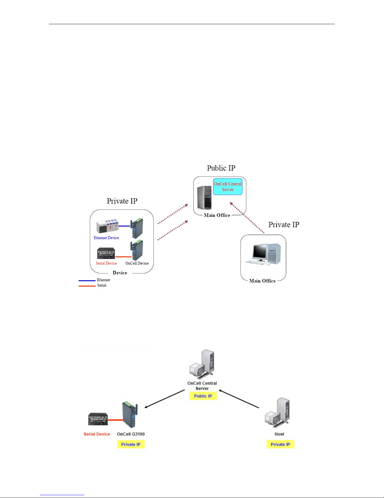
OnCell G3100 Series Introducing OnCell Central and Ethernet Operation Modes
5-2
OnCell Central Management Software
In the cellular world, most service providers only offer private IP addresses to mobile devices due to the limited
availability of public addresses. Mobile devices configured with a private IP address can access resources on the
Internet, but the mobile devices cannot be managed or accessed directly from the Internet since the private IP
address is hidden. The mechanism we developed uses an OnCell server configured with a public IP address to
solve this private IP problem. The OnCell server accepts connections from both Ethernet and serial mobile
devices and remote hosts. Once a connection is established, the mobile device and remote host can
communicate with each other over the pre-established connection. Th is software can be installed by a
customer or hosted by Moxa (for demonstration or testing purposes only) and can be accessed from anywhere
across an IP network, including the Internet.
To illustrate, the following network confi g uration example shows several OnCell devic es, labeled as “OnCell
G3100.” These OnCell devices are all connected to the OnCell Central Server. The host devic e is located in the
same control center as the OnCell Central Server. Please refer to Chapter 11 to configure the OnCell Central
Management Software.
OnCell Central Serial Device Connection
If your device is serial interface, and your cellular service provider assigns you a private IP address after you
connect to the cellular network, Real COM, RFC2217, or TCP Server m ode allow you to access the OnCell G3100
via an OnCell Central Server from host PC.
Page 41
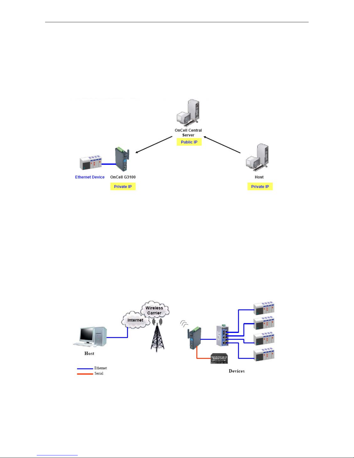
OnCell G3100 Series Introducing OnCell Central and Ethernet Operation Modes
5-3
OnCell Central Ethernet Device Connection
If your device is Ethernet interface, and your cellular service provider assigns you a private IP address after you
connect to the cellular network, service forwarding allows you to access the OnCell G3100 via an OnCell Central
Server from any host PC using either a private IP or public IP address.
Service forwarding, sometimes referred to as port mapping, is the act of forwarding a network port from one
network node to another. This technique can allow an external user to reach a port on a private IP address
(inside a LAN) from the outside via a NAT-enabled IP gateway (OnCell G3100’s NAT original is enabled).
Cellular-Enabling Ethernet Device
Note: This function is only supported by the OnCell G3100 Rev.2.0. Please refer to the
Specifications section of Chapter 1 (page 1-3) for more information.
The OnCell G3100 IP gateway works like a router. All Ethernet devices connected to the OnCell’s LAN port are
hidden via the OnCell’s NAT function. This allows any number of local Ethernet devices to access the Internet
using the OnCell as a gateway. However, the OnCell G3100 appears as just a single IP address on the Internet.
Therefore, incoming connections must be manually forwarded from the OnCell’s public TCP port number to the
internal ports of the local Ethernet devices. Please refer to Chapter 9, Configuring Cellular-Enabling Ethernet
Device.
Page 42

OnCell G3100 Series Introducing OnCell Central and Ethernet Operation Modes
5-4
Virtual Modem Mode
Note: This function is only supported by the OnCell G3100 Rev. 2.0. Please refer to the
Specifications section of Chapter 1 (page 1-3) for more information.
Virtual Modem mode is designed for AT command operating system devices. Its purpose is to extend th e
limited RS-232 cabling distance between computers and modems (Figure 1). The setup in Figure 2 is not an
efficient architecture because we need to deploy extra devices to bridge the gap. A more efficient solution is
provided in Figure 3. By taking advantage of the cable length of Ethernet cables, connecting a properly
configured OnCell IP gateway’s Ethernet port to the device computer’s Ethernet port and installing the Moxa
driver, users can transmit data over a cellul ar network with software originally designed to transmit data
through a modem. Please refer to Chapter 10, Configuring Virtual Modem Mode.
Page 43

6
6. Using the Web Console
The web console is the most user-friendly method available to configure the OnCell G3100. With a standard
web browser, you have easy and intuitive access t o all sett ings and opti ons. In t his chapter, we i ntroduce t he
web console and go through the basic configuration options. The same configuration options are also available
through the Telnet and serial console.
The following topics are covered in this chapter:
Using Your Web Browser
¾ Browser Cookie Settings
¾ Trusted Site Settings
¾ Opening the Web Console
Web Console Navigation
Basic Settings
¾ Server Settings
¾ Time Settings
Network Settings
¾ Basic Network Settings
¾ DNS Settings
¾ Advanced Network Settings
¾ Auto IP Report Settings
GuaranLink Settings (Pending)
¾ Overview
¾ Background
¾ Common Settings
¾ GuaranLink Check Settings
Page 44

OnCell G3100 Series Using the Web Console
6-2
Using Your Web Browser
Browser Cookie Settings
Verify that cookies are enabled for your browser. If the cookies are disabled, you will not be able to use the web
console. (Cookies are only used for password transmission.)
1. For Internet Explorer, enable cookies by selecting Internet Options from the Tools menu:
2. Select the Privacy tab. There are six levels of privacy setting: Block All Cookies, High, Medium High,
Medium, Low, and Accept All Cookies. Users must s el ect Medium High (as the image shows) or below to
access the OnCell G3100 web console.
ATTENTION
If you are not using Internet Explorer, cookies are usually enabled through a web browser setting such as
“
allow cookies that are stored on your computer” or “allow per-session cookies.”
Page 45

OnCell G3100 Series Using the Web Console
6-3
Trusted Site Settings
Windows 2003 users may need to add the OnCell G3100’s IP address to their browser’s list of trusted sites.
1. If you see the following window while attempting to view the web console, click on Add to modify the list of
trusted sites.
You may also access the list of trusted sites directly through Internet Options in the Tools menu of
Internet Explorer. Select the Security tab, click on the Trusted Sites icon, and then select the Sites
button.
Page 46

OnCell G3100 Series Using the Web Console
6-4
2. In either case, the window below should appear, showing the list of sites that you have configured Internet
Explorer to trust. Add the IP address of your OnCell G3100 here (the factory default IP address is
192.168.127.254).
After adding the OnCell G3100’s IP address as a trusted site, you should be able to view the web console by
entering the OnCell G3100’s IP address in your browser’s address bar.
Opening the Web Console
Open your web browser and enter 192.168.127.254 in the website address line. This is the default IP address
for the OnCell G3100—if a new address has been assigned, enter the new address instead. Press ENTER to load
the page.
ATTENTION
The examples and figures in this chapter use the OnCell G3100 factory default IP address of
192.168.127.254. If you have assigned a different IP address to your OnCell G3100, be sure to adjust
accordingly when following these directions. Please refer to Chapter 3, Initial IP Address Configuration, for
details on how to configure the IP address.
Enter the console password if prompted. (This will not apply if you did not enable password protection for your
OnCell G3100.) The password will be transmitted with MD5 encryption over the Internet.
Page 47

OnCell G3100 Series Using the Web Console
6-5
ATTENTION
If you forget your password, the ONLY way to configure the OnCell G3100 is by using the reset button to reset
all settings and load the factory defaults. If you have disabled the reset button in your OnCell G3100
configuration, you may still use it to load the factory defaults within the first 60 seconds that the OnCell G3100
is powered on.
Remember to back up your configuration by exporting it to a file. Your configuration can be easily restored by
importing the file to the OnCell G3100. This will save time if you have forgotten the password and need to
reload the factory defaults.
The OnCell G3100’s web console will appear.
Web Console Navigation
The left panel of the OnCell G3100’s web console is the navigation panel, and contains an expandable menu
tree for navigating among the various settings and categories. When you click on a menu item in the navigation
panel, the main window will display the corresponding options for that item. Configuration changes can then be
made in the main window. For example, if you click on Basic Settings in the navigation panel, the main
window will show a page of basic settings that you can configure.
You must click on the Submit button to keep your configuration changes. The Submit b u tton will be located
at the bottom of every page that has configurable settings. If you navigate to another page without clicking the
Submit button, your settings will not be retained.
Changes will not take effect until they are saved and the OnCell is restarted! You may complete this in
one step by clicking on the Save/Restart option after you submit a change. If you need to make several
changes before restarting, you may save your changes without restarting by selecting Save Configuration in
the navigation panel. If you restart the OnCell G3100 without sa ving your configuration, the OnCell G3100 will
discard all submitted changes.
Basic Settings
The Basic Settings screen can be accessed from the navi gation panel.
Page 48
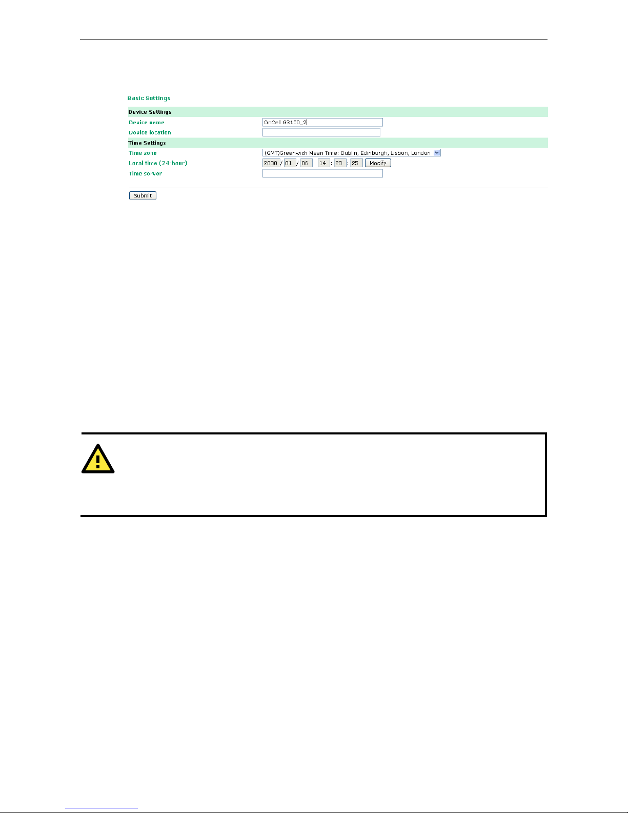
OnCell G3100 Series Using the Web Console
6-6
Server Settings
Device name: This is an optional free text field for your own use; it does not affect the operation of the OnCell
G3100, and can be used to help differentiate one OnCell G3100 server from another.
Device location: This is an optional free text field for your own use; it does not affect the operation of the
OnCell G3100, and is useful for assigning or describing the location of an OnCell G3100. In a network
environment of multiple servers, thi s can be a valuable aid when doing maintenance.
Time Settings
The OnCell G3100 has a built-in Real-Time Clock for time calibration functi ons. Functions such as Auto Warning
Email or SNMP Trap can add real-time information to messages.
Before making any adjustments to the time, first select the correct time zone and submit the change. The
console will display the real time according to the time zone. To modify the real time clock, click on Modify next
to the Local time field. Once you submit the new time, the OnCell G3100’s firmware will modify the GMT time
according to your time zone and local time settings.
ATTENTION
There is a risk of explosion if the real-time clock battery is replaced with the wrong type!
The OnCell G3100’s real time clock is powered by a lithium battery. We strongly recommend that you do not
attempt to replace the lithium battery wit hout help from a qualified Moxa support engineer. If you need to
change the battery, please contact the Moxa RMA service team.
Time zone (default=GMT Greenwich Mean Time): This field shows the currently selected time zone and allows
you to select a different time zone.
Local time: This field shows the time that you last opened or refreshed the browser. To set the local time for
the OnCell G3100, click on the Modify button, update the date and time, and then click on submit.
Page 49
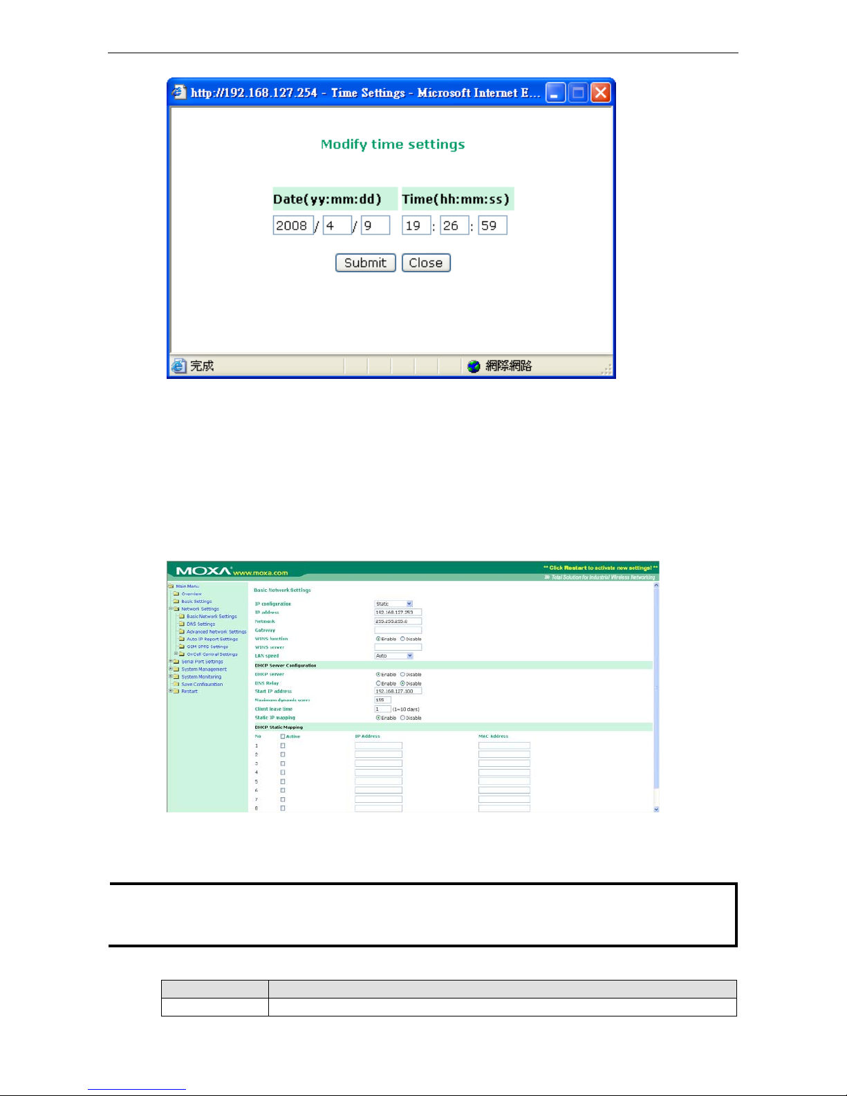
OnCell G3100 Series Using the Web Console
6-7
Time server: The OnCell G3100 uses SNTP (RFC-1769) for auto time calibration. You may enter a time s erver
IP address or domain name in this optional field. Once the OnCell G3100 is configured with the correct time
server address, it will request time information from the time server every 10 minutes.
Network Settings
Basic Network Settings
You can access Basic Network Settings by expanding the Network Settings item in the navigation panel.
Basic Network Settings is where you assign the OnCell G3100’s IP address, netmask, Gateway, and other
parameters for the Ethernet interface.
NOTE You must assign a valid IP address to your OnCell G3100 before it will work in your network environment.
Your network system administrator should provide you with a unique IP address and related settings for your
network. First-time users can refer to Chapter 3: Initial IP Address Configuration, for more information.
IP configuration (default=Static): You can choose from four possible IP configur ation modes.
Option Description
Static User-defined IP address, netmask, and gateway.
Page 50

OnCell G3100 Series Using the Web Console
6-8
DHCP DHCP server-assigned IP address, netmask, gateway, and DNS
DHCP/BOOTP DHCP server-assigned IP address, netmask, gateway, and DNS, or BOOTP
server-assigned IP address (if the DHCP server does not respond)
BOOTP BOOTP server-assigned IP address
IP Address (default=192.168.127.254): Enter the IP address that will be assigned t o your OnCell G3100. All
ports on the OnCell G3100 will share this IP address. An IP address is a number assigned to a network device
(such as a computer) as a permanent address on the network. Computers use the IP address to identify and
talk to each other over the network. Choose a proper IP address that is unique and valid for your network
environment.
Netmask (default=255.255.255.0): Enter the subnet m ask. A subnet mask represents all of the network hosts
at one geographic location, in one building, or on the same local area network. When a packet is sent out over
the network, the OnCell G3100 will use the subnet mask to check whether the desired TCP/IP host specified in
the packet is on the local network segment. If the address is on the same network segment as the OnCell
G3100, a connection is established directly from the OnCell G3100. Otherwise, the connection is established
through the given default gateway.
Gateway: Enter the IP address of the gateway if applicable. A gateway is a network computer that acts as an
entrance to another network. Usually, the computers that control traffic within the network or at the local
Internet service provider are gateway nodes. The OnCell G3100 needs to know the IP address of the default
gateway computer in order to communicate with the host s outside the local network environm ent. For correct
gateway IP address information, consult the network administrator.
ATTENTION
In dynamic IP environments, the firmware will try to get the network settings from the DHCP or BOOTP server
3 times every 30 seconds until network settings are assigned by the DHCP or BOOTP server. The first try times
out after 1 second, the second after 3 seconds, and the thi r d after 5 seconds.
If the DHCP/BOOTP server is unavailable, the firmware will use the default IP address (192.168.127.254),
netmask, and gateway settings.
WINS function (default=enable): Enable or disable the WINS (Windows Internet Naming Service) serv er.
WINS server: If a WINS Server is connected to the network, enter the WINS Server’s IP address in this field.
TCP/IP uses IP addresses to identify hosts, but users often use symbolic names, such as computer names. The
WINS Server, which uses NetBIOS over TCP/IP, contains a dynamic database to map computer names to IP
addresses.
LAN speed (default=Auto): You may configure the network speed for the built-in Ethernet connection on the
OnCell G3100. IEEE802.3 Ethernet supports auto negotiation of transfer speed. However, some switches/hubs
require that the communication speed be fixed at 100 Mbps or 10 Mbps.
DHCP (default=Enable): DHCP stands for Dynamic Host Control Protocol. When you enable the DHCP Server,
it will automatically assign an IP address to the computers on the LAN or private network. Be sure to set your
computers to be DHCP clients by setting their TCP/IP settings to “Obtain an IP Address Automatically.” When
you turn your computers on, they will automatically load the proper TCP/IP set tings provided by the OnCell
5000. The DHCP Server will automatically allocate an unused IP address from the IP address pool to the
requesting computer. You must specify the starting and ending address of the IP address pool.
DNS relay (default=Enable): If you enable DNS relay, your co mputers will use the router as a DNS server. If
you disable DNS relay, transfer the DNS server information from your ISP to your computers.
Start of dynamic IP address: Enter the starting IP addresses for the DHCP server's IP assignment.
Maximum dynamic users: Enter the number of dynamic users. The maximum users you can enter may not
exceed 253, if your dynamic IP address begins with 192.168.127.1
Note: If you statically (manually) assign IP addresses to your computers or devices, make sure the IP
addresses are outside of this range or you may have an IP conflict.
Page 51
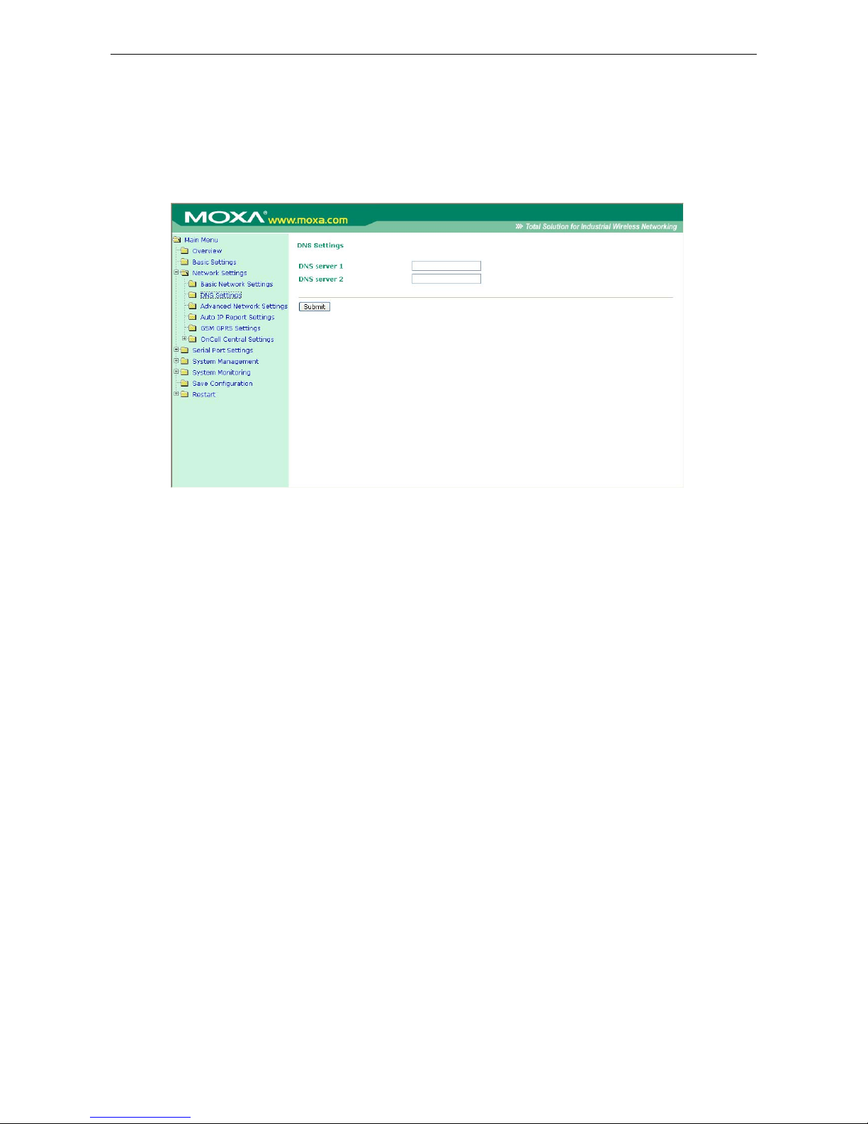
OnCell G3100 Series Using the Web Console
6-9
Client lease time: The length of time for the IP address lease. Enter the Lease time in minutes.
Static IP mapping: If enabled, the mapping list allows you to assign the DHCP IP within the range to your
specific device from MAC address.
DNS Settings
DNS server 1: This is an optional field. If your network has access to a DNS server, you may enter the DNS
server’s IP address in this field. This allows the OnCell 5000 to use domain names instead of IP addresses to
access hosts.
The Domain Name System (DNS) is used to identify Internet domain names, and translate the names into IP
addresses. A domain name is an alphanumeric name, such as www.moxa.com, that it is usually easier to
remember than the numeric IP address. A DNS server is a host that translates this kind of text-based domain
name into the actual IP address used to establish a TCP/IP connection.
When the user wants to visit a particular website, the user’s computer sends the domain name (e.g.,
www.moxa.com) to a DNS server to request that website’s numeric IP address. When the IP address is
received from the DNS server, the user’s computer uses that information to connect to the website’s web
server. The OnCell 5000 plays the role of a DNS client, i n the se nse th at it acti vely queries t he DNS s erver for
the IP address associated with a particular domain name. The following functions in the OnCell 5000’s web
console support the use of domain names in place of IP addresses: Time Server, Destination IP Address (in TCP
Client mode), Mail Server, SNMP Trap Server, and SMTP Server.
DNS server 2: This is an optional field. The IP address of another DNS server may be entered in this field for
times when DNS server 1 is unavailable.
Advanced Network Settings
Access Advanced Networ k Settings by expanding the Network Settings item in the navigation panel.
Advanced Network Settings is where the gratuitous ARP is configured.
Page 52
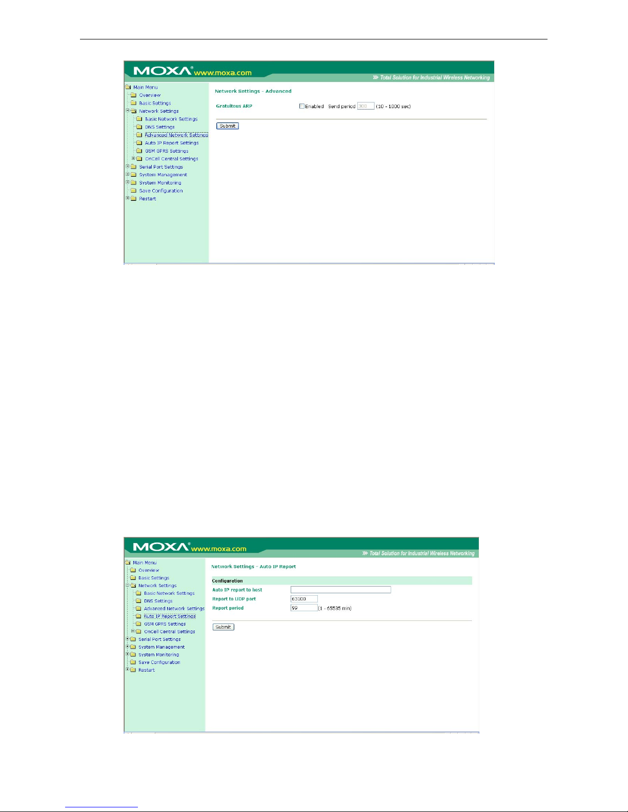
OnCell G3100 Series Using the Web Console
6-10
Gratuitous ARP: In some applications, you may need the OnCell G3100 to send broadcast packets to update
the ARP table on the server. If you enable this function and set the send period, the OnCell G3100 will
periodically send broadcast packets at the specified time interval.
Auto IP Report Settings
Access Auto IP Report Settings by expanding the Network Settings item in the navigation panel.
When the OnCell G3100 products are used in a dynamic IP environment, users m ust spend more t ime with IP
management tasks. For example, if the OnCell works as a server (TCP or UDP), then the host, which acts as a
client, must know the IP address of the server. If the DHCP server assigns a new IP address to OnCell, the host
must have some way of determining OnCe ll’s new IP address.
OnCell G3100 products help out by periodically reporting their IP address to the IP location server, in case the
dynamic IP has changed. The parameters shown below are used to configure the Auto IP report function. There
are two ways to develop an “Auto IP report Server” to receive the OnCell’s Auto IP report.
Use the OnCell Search Utility’s IP Address Report function. Please refer to OnCell Search Utility Configuration
in Chapter 14.
“Auto IP report protocol,” which can automatically receive the Auto IP report on a regular basis, is also available
to help you develop your own software. Refer to Appendix E for the “Auto IP report protocol.”
Page 53
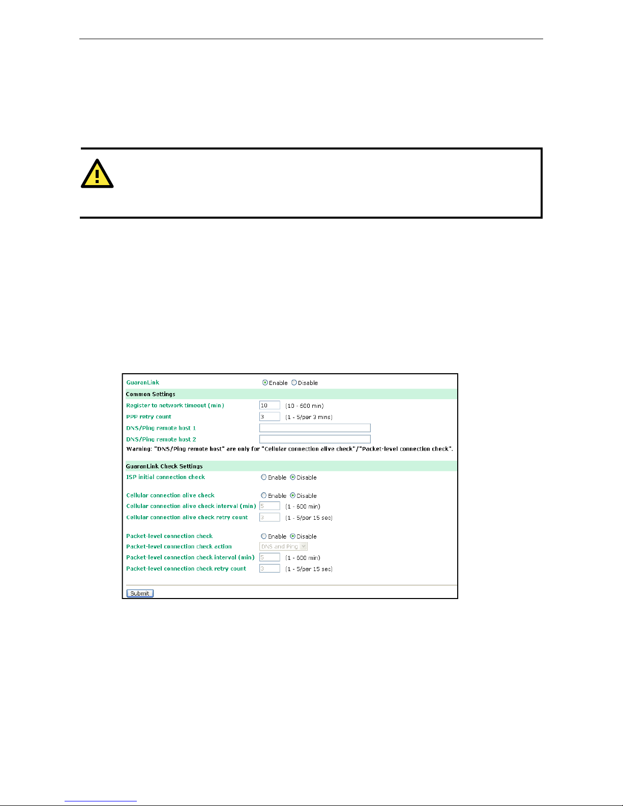
OnCell G3100 Series Using the Web Console
6-11
Auto IP report to host: Reports generated by the Auto report function will be sent automatically to this IP
address or host name.
Report to UDP port (default=63100): This is the UDP port number assignment for the serial port on the
OnCell G3100.
Report period (default =99): You can use this option to set how often the I P address is automatically
reported.
ATTENTION
To use the OnCell Search Utility to receive the auto IP report message sent from the OnCell G3100, please
also install OnCell Windows Driver Manager. OnCell Windows Driver Manger helps dispatch messages to the
OnCell Search Utility.
GuaranLink Settings (Pending)
Overview
Connection failures of wireless connections can be caused by a number of different factors, including loss of
cellular signal, interference, or termination by the operator for unknown reasons. Typically, cellular routers will
not be alerted when a connection is terminated due to inactivity. Since maintaining a stable cellular connection
is important for a number of obvious reasons, OnCell cellular routers offer the GuaranLink function, which
ensures that your wireless connection will be there whenever you need it.
Background
“Register to network” and “Establish PPP with ISP” are two steps for establishing connection with the ISP.
If GuaranLink determines that the OnCell cannot establish a connection with the ISP, it reboots the OnCell in
order to allow the OnCell to retry the connection once it reboots.
Page 54

OnCell G3100 Series Using the Web Console
6-12
Common Settings
GuaranLink (default=Disable): Enable this setting to start the GuaranLink function.
Register to network timeout (min) (default=10): This setting specifies how long GuaranLink should wait
to register to the network before the OnCell reboots itself.
PPP retry count (default=3 mins) This setting specifies how many times GuaranLink should retry
establishing PPP with the ISP before OnCell reboots itself.
DNS/Ping remo t e host 1 and DNS/Ping remote host 2: This setting is for “Cellular connection alive
check” and “Packet-level connection check.” It specifies the target host of the DNS lookup and Ping action.
Can be either a domain name or an IP address.
GuaranLink Check Settings
ISP initial connection check (defau lt =Disable): This function ensures that the OnCell can establish a
connection with an ISP after it reboots.
Cellular connection alive check (default=Disable): Some ISPs may disable the connection if no data is
transmitted in a specific period of time. This function ensures that the cellular connection will be kept alive even
if no data is transmitted for a period of time by performing the check action of DNS lookup or ping action of
DNS/Ping remote host 1 or DNS/Ping remote host 2. If the check action fails after the retry count number
specified in “Cellular connection alive check retry count”, the OnCell will re-establish a connection with the ISP.
Cellular connection alive check in t erval (min) (default=5 min): This setting spe cifies the idle time
before GuaranLink performs the check action.
Cellular connection alive check retry count (default=3 sec): This setting specifies the number of
attempts to reach the remote target(s) before the OnCell re-establishes a connection.
Packet-level connection check (default=Disable): This function checks if the cellular network can be
accessed by performing the check action of lookup DNS or ping action of DNS/Ping remote host 1 or DNS/Ping
remote host 2. If the check action fails after the retry count number specified in “Packet-level connection check
retry count.” the OnCell will re-establish a connection with ISP.
Packet-level connection check action (default=DNS and PING): This setting specifies whether the check
action is successful when both of the DNS lookup and the ping action succeed, or if it is successful even if only
one of them succeed.
Packet-level connection check interval (min) (default =5 min): T h is sett ing spe cif ies th e interv a l
between two check actions.
Packet-level connection check retry count (default=3 sec): This setting specifies the number of
attempts to reach the remote target(s) before the OnCell re-establishes a connection.
Page 55

7
7. Cellular Network Settings
In this chapter, we describe how to set up cellular networks, including GSM, GPRS, EDGE, UMTS, HSDPA and
SMS. The configuration options discussed here are also available from the Telnet and serial consoles.
The following topics are covered in this chapter:
GSM GPRS Settings (For OnCell G3110 and G3150)
Cellular Setting (OnCell G3110-HSDPA and OnCell G3150-HSDPA)
Cellular Setting (OnCell G3110-HSDPA-JPS, OnCell G3150-HSDPA-JPS, OnCell
G3110-HS
DPA-JPN, OnCell G3150-HSDPA-JPN)
¾ GSM or GSM (CSD) Operation Mode
¾ GPRS or GPRS/EDGE/UMTS/HSDPA Operation Mode
¾ SMS Operation mode
¾ Virtual Modem Operation mode
Page 56
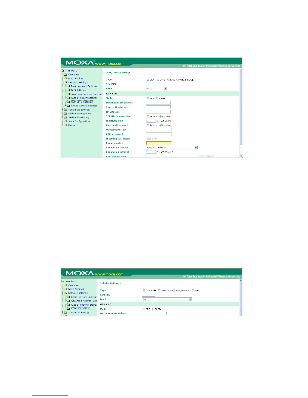
OnCell G3100 Series Cellular Network Settings
7-2
GSM GPRS Settings (For OnCell G3110 and
G3150)
From the left navigation panel, click Network Settings Æ GSM GPRS Settings to configure the
GSM/GPRS/SMS Settings. The various configuration items are described below:
Type: The OnCell G3100 supports 3 types of operation modes. You may choose from GSM, GPRS, and SMS.
SIM PIN: This is a pin code that locks the SIM card until you enter the correct code. Use the pin to protect your
account. The default code is set by the Service Provider. Note that a cell phone must be used to change the PIN.
Selecting the Radio Band: Although GSM-900 and GSM-1800 are used in most parts of the world, operators
in United States, Canada, and many other countries in the Americas use GSM-850 or GSM-1900. The
GSM/GPRS band of GSM/GPRS/EDGE module is configured to auto by default.
Additional settings for each of the three modes are described in the following subsections.
Cellular Setting (OnCell G3110-HSDPA and
OnCell G3150-HSDPA)
From the left navigation panel, click Network Settings Æ Cellular Settings to configure the
GSM/GPRS/EDGE/UMTS/HSDPA/SMS Settings. The various configuration items are described below:
Type: The OnCell G3100 supports 3 types of operation mode. You may choose from GSM (CSD),
GPRS/EDGE/UMTS/HSDPA, and SMS.
SIM PIN: This is a pin code that locks the SIM card until you enter the correct code. Use the pin to protect your
account. The default code is set by the Service Provider. Note that a cell phone must be used to change the PIN.
Page 57
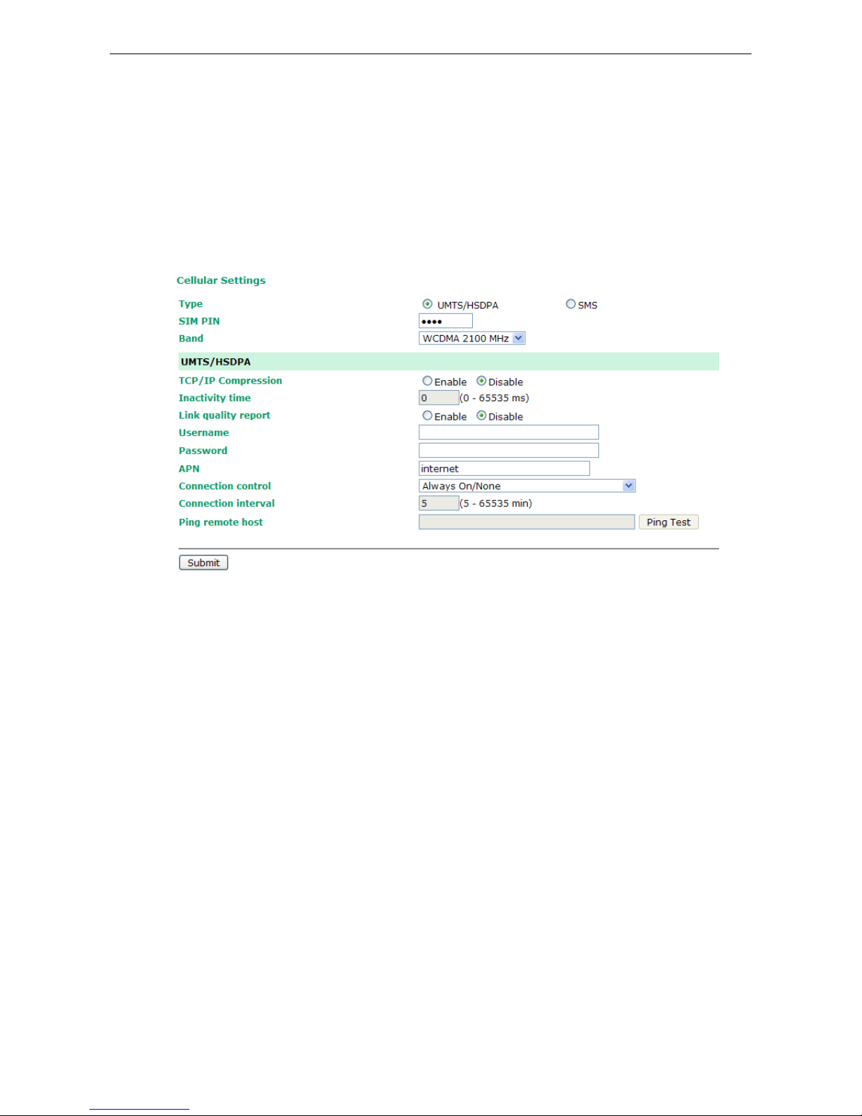
OnCell G3100 Series Cellular Network Settings
7-3
Selecting the Radio Band: Although GSM-900 and GSM-1800 are used in most parts of the world, operators
in United States, Canada, and many other countries i n the Ame ricas use GSM- 850, GSM-1900, or GSM- 2100.
The GSM/GPRS/EDGE/UMTS/HSDPA band for the module is configured to auto by default.
Cellular Setting (OnCell G3110-HSDPA-JPS,
OnCell G3150-HSDPA-JPS, OnCell
G3110-HSDPA-JPN, OnCell G3150-HSDPA-JPN)
From the left navigation panel, click Network Settings Æ Cellular Settings to configure the
UMTS/HSDPA and SMS Settings. The various configuration items are described below:
Type: The OnCell G3100 supports 1 type of operation mode. You can choose from UMTS/HSDPA and SMS.
SIM PIN: This is a pin code that locks the SIM card until you enter the correct code. Use the pin to protect your
account. The default code is set by the Service Provider. Note that a cell phone must be used to change the PIN.
Selecting the Radio Band: Only the 2100 band can be selected in Japan model.
Page 58

OnCell G3100 Series Cellular Network Settings
7-4
GSM or GSM (CSD) Operation Mode
PPP Mode: PPP provides standard PPP dial-out service.
PPPD Mode: PPPD (PPP Daemon) is used for dial-in services, since it provides PPP services only when
receiving a request from a remote PC.
Destination IP address, Source IP address, IP netmask: If you do not configure these three parameters,
they will be filled in automatically by the remote side of the connection.
TCP/IP compression (default=Disa b l e): The setting of this field depends on whether the remote user’s
application requests compression.
Inactivity time (default=0 ms): This field specifies the idle time setting for auto-disconnection. A setting of
0 ms will cause the port to remain connected even if idle.
Link quality report (default=Disable): Setting this field to Enable allows the OnCell G3100 to disconnect a
connection if the link noise exceeds a certain threshold.
Outgoing PAP ID: This is the dial-out user ID account.
PAP password: This is the dial-out user password.
Incoming PAP check (default=None): This field allows you to configure the method used, if any, to verify
a user’s ID and authorization.
Option Description
Local Verify the ID against the OnCell G3100 password. The user name for the OnCell
G3100 is fixed to “admin.”
None Authentication is not required.
Phone number: Use this field to configure the number used to dial out.
Initial string: Use this field to configure the initial string that the modem will use to establish the connection.
Connection control Connect Rule Disconnect Rule GSM
Always on/None Always on after power on None Trunk
Periodically
connect/inactivity time
Periodically connect (based on the
connection interval setting) to GSM
after power on.
Inactivity time is up Trunk
Page 59
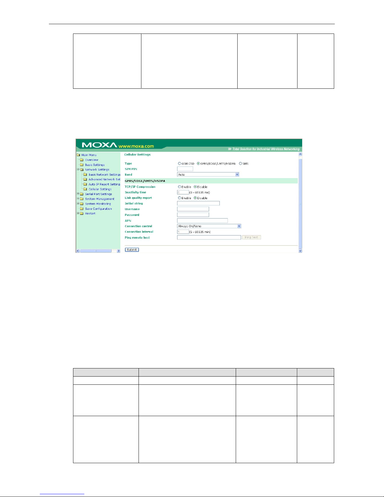
OnCell G3100 Series Cellular Network Settings
7-5
Remote host fail/remote
host recovered
Remote Ethernet host has failed. The
OnCell G3100 will keep pinging the
remote host over the Ethernet every 3
seconds after powering on. After failing
to connect 5 times in a row, the data
from the serial device will be sent
through the GSM connection.
When the remote
Ethernet host returns to
normal, data will revert
to being sent over
Ethernet after 5
continuous successful
pings.
Backup
Connection interval (default= 5 min): The time interval of the periodically connect function.
Ping remote host: Key in the IP address or Domain name of the remote host.
GPRS or GPRS/EDGE/UMTS/HSDPA Operation Mode
TCP/IP compression (default=Disa b l e): The setting of this field depend on whether or not the remote
user’s application requests compression.
Inactivity time (default=0 ms): This field specifies the idle time setting for auto-disconnection. A setting of
0 ms will cause the port to remain connected even if idle.
Link quality report (default=Disable): Setting this field to Enable allows the OnCell G3100 to disconnect a
connection if the link noise exceeds a certain threshold.
Initial string: Use this field to configure the initial string that the modem will use to establish the connection.
Username: This is the user ID account.
Password: This is the user password.
APN: Before using the GPRS/UMTS/HSDPA also need APN (Access Point Name) must be added as a modem
initialization command. Detailed instructions are shown below.
Connection control Connect Rule Disconnect Rule GPRS
Always on/None Always on after power on None Trunk
Periodically connect/
inactivity time
Periodically connect (based on the
connection interval setting) attempt to
connect to UMTS/HSDPA first then
GPRS after powering on.
Inactivity time is up Trunk
Remote host fail/
remote host recovered
Remote Ethernet host has failed. The
OnCell G3100 will keep pinging the
remote host over the Ethernet every 3
seconds after powering on. After failing
to connect 5 times in a row, the data
from the serial device will be sent
When the remote
Ethernet host returns to
normal, data will revert
to being sent over
Ethernet after 5
continuous successful
Backup
Page 60

OnCell G3100 Series Cellular Network Settings
7-6
through the HSDPA/UMTS first then
GPRS connection.
pings.
Connection interval (default = 5 min): The time interval of the periodic connect function.
Ping remote host: Key in the IP address of the remote host.
SMS Operation mode
Short Message Service (SMS) is a telecommunications protocol that all ows sending “short” (160 characters or
less) text messages. It is available on most digital mobile phones and some personal digital assistants with
built-in wireless capability.
GSM technology offers the benefit of using SMS (short message service) as an easy way to communicate over
the mobile network. In the next chapter, we explain how to use SMS w it h the OnCell G3100.
Virtual Modem Operation mode
Virtual Modem mode is designed for AT command operating system devices. For more details, please refer to
Chapter 5 for an introduction and Chapter 10 for configuration settings.
Page 61

8
8. Configuring Serial Port Operation Modes
In this chapter, we explain how to configure the individual serial port modes.
The following topics are covered in this chapter:
Port Setting Basics
Device Control Applications
¾ Real COM Mode
¾ Reverse Real COM Mode
¾ RFC2217 Mode
Socket Applications
¾ TCP Server Mode
¾ TCP Client Mode
¾ UDP Mode
Ethernet Modem Mode
SMS Tunnel Mode
Disabled Mode
Page 62
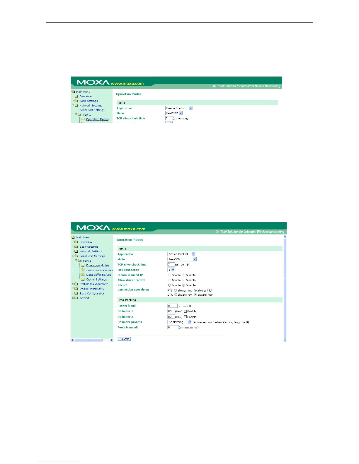
OnCell G3100 Series Configuring Serial Port Operation Modes
8-2
Port Setting Basics
To configure the operation mode and settings for a port, expand Serial Port Settings in the navigation panel,
and then expand the port that you would like to configure. Individual port settings are grouped into three
categories in the navigation panel: Operation Modes, Communication Parameters, and Data Buffering/Log.
Select Operation Modes in the navigation panel to select and configure the mode for each serial port.
Application: Select an application for the serial port from among the choices. Your application will determine
the modes that are available.
Mode: Once you have chosen an application, select the mode. The available configuration settings will vary
depending on the mode that you have selected.
Device Control Applications
Real COM Mode
TCP alive check time (default=7 min): This field specifies how long the OnCell G3100 will wait for a response
to “keep alive” packets before closing the TCP connection. The OnCell G3100 checks connection status by
sending periodic “keep alive” packets. If the remote host does not respond to the packet within the time
specified in this field, the OnCell G3100 will force the existing TCP connection to close. For socket and device
control modes, the OnCell G3100 will listen for another TCP connection from another host after closing the
connection. If TCP alive check time is set to 0, the TCP connection will remain open and will not send any
“keep alive” packets.
Max connection (default=1): This field is used if you need to receive data from different hosts
simultaneously. When set to 1, only one speci fic host can access this port of the OnCell G3100, and the OnCell
COM driver on that host will have full control over the port. When set to 2, the specified number of hosts’ OnCell
COM driver may open this port at the same time. When multiple hosts’ OnCell COM driver open the port at the
Page 63

OnCell G3100 Series Configuring Serial Port Operation Modes
8-3
same time, the COM driver only provides a pure data tunnel --no control ability unless “Allow Driver Control” is
enabled. The serial port parameters will use firmware settings instead of depending on your application
program (AP).
Application software that is based on the COM driver will receive a driver response of “success” when the
software uses any of the Win32 API functions. The firmware will only send data back to the driver on the host.
Data will be sent first-in-first-out when data comes into the OnCell G3100 from the Cellular or Ethernet
interface.
ATTENTION
When Max connection is greater than 1, the OnCell G3100 will use a multi connection application (i.e., 2
hosts are allowed access to the port at the same time). When using a multi connection application, the OnCell
G3100 will use the serial communication parameters as defined here in the web console, and all hosts
connected to the port must use identical serial settings. If one of the hosts opens the COM port with different
serial settings, data will not be transmitted properly.
Ignore jammed IP (default=Disable): This option determines how the port will proceed if multiple hosts are
connected and one or more of the hosts stops responding as the port is transmitting data. If you select Disable,
the port will wait until the data has been transmitted successfully to all hosts before transmitting the next group
of data. If you select Enable, the port will ignore the host that stopped responding and continue data
transmission to the other hosts.
Allow driver control (default=Disable): This option determines how the port will proceed if driver control
commands are received from multiple hosts that are connected to the port. If Disable is selected, driver
control commands will be ignored. If Enable is selected, control commands will be accepted, with the most
recent command received taking precedence.
Secure (default=Disable): If you select Enable, data sent through the Ethernet will be encrypted with SSL.
ATTENTION
If your OnCell G3100 serial port is in Real COM or Reverse Real COM mode and is configured for SSL
encryption, make sure the COM driver is configured the same way. This is done with OnCell Windows Driver
Manager, which is installed with the driver. Please refer to Chapter 14, Software Installation/Configuration,
for more information.
Connection goes down (default=always high): You can configure what happens to the RTS and DTR signals
when the Cellular or Ethernet connection goes down. For some applications, serial devices need to k now the
Cellular or Ethernet link stat us through RTS or DTR sign als sent through the serial port. Use “always low” if you
want the RTS and DTR signal to change their state to low when the Cellular or Ethernet connection gets
disconnected. Use “always high” if you do not want the cellular or Ethernet connection status to affect the RTS
or DTR signals.
Packet length (default=0): The Packet length setting refers to the maximum amount of data that is allowed
to accumulate in the serial port buffer before sending. At the default of 0 for packet length, no maximum
amount is specified and data in the buffer will be sent as specified by the delimiter settings or when the buffer
is full. When a packet length between 1 and 1024 bytes is specified, data in the buffer will be sent as soon it
reaches the specified length.
Delimiter 1 and Delimiter 2 (default=None): When Delimiter 1 is enabled, the serial port will queue the data
in the buffer and send the data to the Cellular or Ethernet port when a specific character, entered in hex format,
is received. A second delimiter character may be enabled and specified in the Delimiter 2 field, so that both
characters act as the delimiter to control when data should be sent.
Page 64

OnCell G3100 Series Configuring Serial Port Operation Modes
8-4
ATTENTION
In order to enable a delimiter, packet length must be set to 0. Delimiter 2 should only be enabled in
conjunction with Delimiter 1 and never on its own; otherwise there may be data errors. Even when a delimiter
is enabled, the OnCell G3100 will still pack and send the data when the amount of data exceeds 1 KB.
Delimiter process (default=Do Nothing): The Delimiter process field determines how the data is handled
when a delimiter is received. Delimiter 1 must be enabled for this field to have effect. If Delimiters 1 and 2 are
both enabled, both characters must be received for the delimiter process to take place.
• Do Nothing: Data in the buffer will be transmitted when the delimiter is received.
• Delimiter + 1: Data in the buffer will be transmitted after 1 additional byte is received following the
delimiter.
• Delimiter + 2: Data in the buffer will be transmitted after 2 additional bytes are received following the
delimiter.
• Strip Delimiter: Data in the buffer is first stripped of the delimiter before being transmitted.
Force transmit (default=0 ms): This parameter defines how larg e a gap in serial communication the OnCell
G3100 will allow before packing the serial data in its internal buffer for network transmission.
As data is received through the serial port, it is stored by the OnCell G3100 in the internal buffer. The OnCell
G3100 transmits data stored in the buffer via TCP/IP, but only when the internal buffer is full or as specified by
the force transmit time. When set to 0, the force transmit time is disabled, and transmission is determined
solely by the data in the internal buffer. At 1 to 65535, the TCP/IP protocol software will pack the serial data
received after there is a gap in serial communication that exceeds the specified force transmit time.
The optimal force transmit time depends on your application, but it must be at least larger than one character
interval within the specified baudrate. For example, assume that the se rial port is set to 1200 bps, 8 dat a bits,
1 stop bit, and no parity. In this case, the total number of bits needed to send a character is 10 bits, and the
time required to transfer one character is
(10 (bits) / 1200 (bits/s)) × 1000 (ms/s) = 8.3 ms.
Therefore, you should set the force transmit time to be greater than 8.3 ms, so in this case, it must be greater
than or equal to 10 ms.
If it is necessary to send a series of characters in the same packet, the serial device will need to send that series
of characters within the specified force transmit time, and the total length of data must be less than or equal
to the OnCell G3100’s internal buffer size (1 KB per port).
Page 65
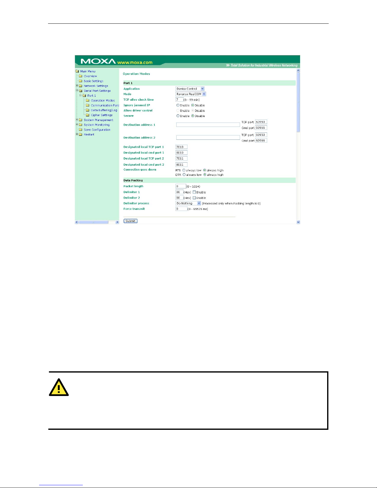
OnCell G3100 Series Configuring Serial Port Operation Modes
8-5
Reverse Real COM Mode
TCP alive check time (default=7 min): This field specifies how long the OnCell G3100 will wait for a
response to “keep alive” packets before closing the TCP connection. The OnCell G3100 checks the connection
status by sending periodic “keep alive” packets. If the remote host does not respond to the packet within the
time specified in this field, the OnCell G3100 will force the existing TCP connection to close. For socket and
device control modes, the OnCell G3100 will listen for another TCP connection from another host after closing
the connection. If TCP alive check time is set to 0, the TCP connection will remain open and will not send any
“keep alive” packets.
Max connection (default=1): This field is used if you need to receive data from different hosts
simultaneously. When set to 1, only one speci fic host can access this port of the OnCell G3100, and the OnCell
COM driver on that host will have full control over the port. When set to 2, the specified number of hosts’ OnCell
COM driver may open this port at the same time. When multiple hosts’ OnCell COM driver open the port at the
same time, the COM driver only provides a pure data tunnel with no control ability. The serial port parameters
will use firmware settings instead of depending on your application program (AP).
Application software that is based on the COM driver will receive a driver response of “success” when the
software uses any of the Win32 API functions. The firmware will only send data back to the driver on the host.
Data will be sent first-in-first-out when data comes into the OnCell G3100 from the Cellular or Ethernet
interface.
ATTENTION
When Max connection is greater than 1, the OnCell G3100 will use a multi connection application (i.e., 2
hosts are allowed access to the port at the same time). When using a multi connection application, the OnCell
G3100 will use the serial communication parameters as defined here in the web console, and all hosts
connected to the port must use identical serial settings. If one of the hosts opens the COM port with different
serial settings, data will not be transmitted properly.
Ignore jammed IP (default=Disable): This option determines how th e port will proceed if multiple hosts
are connected and one or more of the hosts stops responding as the port is tra nsmitting data. If you select
Page 66
OnCell G3100 Series Configuring Serial Port Operation Modes
8-6
Disable, the port will wait until the data has been transmitted successfully to all hosts before transmitting the
next group of data. If you select Enable, the port will ignore the host that stopped responding and continue
data transmission to the other hosts.
Allow driver control (default=Disable): This option determines how the port will proceed if driver control
commands are received from multiple hosts that are connected to the port. If Disable is selected, driver
control commands will be ignored. If Enable is selected, control commands will be accepted, with the most
recent command received taking precedence.
Secure (default=No): If you select Yes, data sent through the Ethernet will be encrypted with SSL.
ATTENTION
If your OnCell G3100 serial port is in Reverse Real COM mode and is configured for SSL encryption, make sure
the OnCell COM driver is configured the same way. Please refer to Chapter 14, Software
Installation/Configuration, for more information.
Destination address 1 through 2 (default=None): Specifying an IP address allows the OnCell G3100 to
connect actively to the remote host. At least one destination must be provided.
TCP port (default=63950): This is the TCP port number assignm ent for the remote host/server. It is the port
number that the OnCell G3100’s serial port uses to establish connections with a remote host/se rver. To avoid
conflicts with well known TCP ports, the default is set to 63950.
Command port (default=63966): The Command port is the COM port for listening to SSDK commands from
the host. In order to prevent a COM port conflict with other applications, the user can set the Command port to
another port if needed.
ATTENTION
Up to 2 connections can be established between OnCell G3100 hosts.
Port 63950 might be blocked by a firewall. You should make sure the port is NOT blocked before you start
using it.
ATTENTION
The destination IP address parameter can be the IP address, domain name, or the name defined in the host
table.
Designated local port 1 through 2 (default=7010 through 7320): Use these fields to specify the
designated local ports.
Connection goes down (default=always high): You can configure what happens to the RTS and DTR
signals when the Cellular or Ethernet connection goes down. For some applications, serial devices need to know
the Cellular or Ethernet link status through RTS or DTR signals sent through the serial port. Use “always low”
if you want the RTS and DTR signal to change their state to low when the Cellular or Ethernet connection gets
disconnected. Use “always high” if you do not want the cellular or Ethernet connection status to affect the RTS
or DTR signals.
Packet length (default=0): The Packet length setting refers to the maximum amount of data that is allowed
to accumulate in the serial port buffer before sending. At the default of 0 for packet length, no maximum
amount is specified and data in the buffer will be sent as specified by the delimiter settings or when the buffer
is full. When a packet length between 1 and 1024 bytes is specified, data in the buffer will be sent as soon it
reaches the specified length.
Delimiter 1 and Delimiter 2 (default=None): When D elimiter 1 is enabled, the serial port will queue the
data in the buffer and send the data to the Cellular or Ethernet port when a specific character, entered in hex
format, is received. A second delimiter character may be enabled and specified in the Delimiter 2 field, so that
both characters act as the delimiter to control when data should be sent.
Page 67
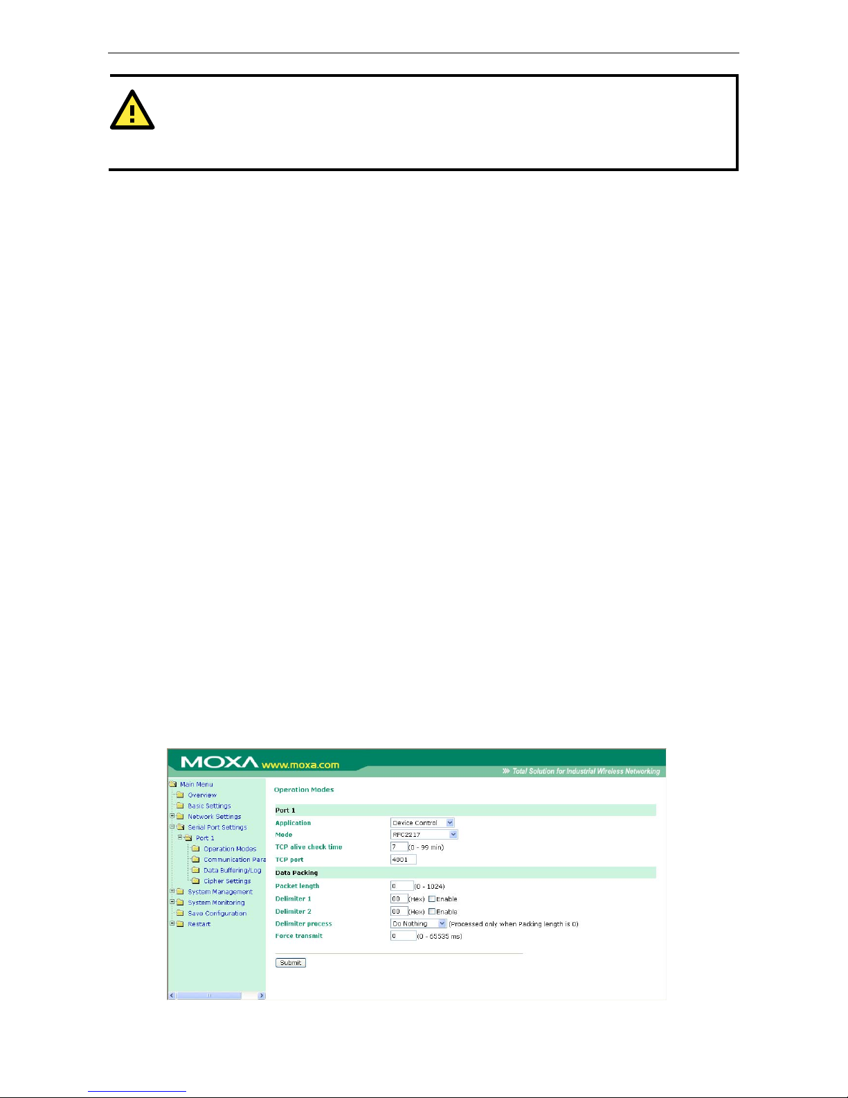
OnCell G3100 Series Configuring Serial Port Operation Modes
8-7
ATTENTION
In order to enable a delimiter, packet length must be set to 0. Delimiter 2 should only be enabled in
conjunction with Delimiter 1 and never on its own; otherwise there may be data errors. Even when a delimiter
is enabled, the OnCell G3100 will still pack and send the data when the amount of data exceeds 1 KB.
Delimiter process (default=Do Nothing): The Delimiter process field determines how the data is handled
when a delimiter is received. Delimiter 1 must be enabled for this field to have effect. If Delimiters 1 and 2 are
both enabled, both characters must be received for the delimiter process to take place.
Do Nothing: Data in the buffer will be transmitted when the delimiter is received.
Delimiter + 1: Data in the buffer will be transmitted after 1 additional byte is received following the delimiter.
Delimiter + 2: Data in the buffer will be transmitted after 2 additional bytes are received following the
delimiter.
Strip Delimiter: Data in the buffer is first stripped of the delimiter before being transmitted.
Force transmit (default=0 ms): This parameter defines how large a gap in serial communication the OnCell
G3100 will allow before packing the serial data in its internal buffer for network transmission.
As data is received through the serial port, it is stored by the OnCell G3100 in the internal buffer. The OnCell
G3100 transmits data stored in the buffer via TCP/IP, but only when the internal buffer is full or as specified by
the force transmit time. When set to 0, the force transmit time is disabled, and transmission is determined
solely by the data in the internal buffer. At 1 to 65535, the TCP/IP protocol software will pack the serial data
received after there is a gap in serial communication that exceeds the specified force transmit time.
The optimal force transmit time depends on your application, but it must be at least larger than one character
interval within the specified baudrate. For example, assume that the se rial port is set to 1200 bps, 8 dat a bits,
1 stop bit, and no parity. In this case, the total number of bits needed to send a character is 10 bits, and the
time required to transfer one character is
(10 (bits) / 1200 (bits/s)) × 1000 (ms/s) = 8.3 ms.
Therefore, you should set the force transmit time to be greater than 8.3 ms, so in this case, it must be greater
than or equal to 10 ms.
If it is necessary to send a series of characters in the same packet, the serial device will need to send that series
of characters within the specified force transmit time, and the total length of data must be less than or equal
to the OnCell G3100’s internal buffer size (1 KB per port).
RFC2217 Mode
Page 68

OnCell G3100 Series Configuring Serial Port Operation Modes
8-8
TCP alive check time (default=7 min): This field specifies how long the OnCell G3100 will wait for a response
to “keep alive” packets before closing the TCP connection. The OnCell G3100 checks connection status by
sending periodic “keep alive” packets. If the remote host does not respond to the packet within the time
specified in this field, the OnCell G3100 will force the existing TCP connection to close. For socket and device
control modes, the OnCell G3100 will listen for another TCP connection from another host after closing the
connection. If TCP alive check time is set to 0, the TCP connection will remain open even if there is no
response to the “keep alive” packets.
TCP port (default=4001): This is the TCP port number assignment for the serial port on the OnCell G3100. It
is the port number that the serial port uses to listen to connections, and that other devices must use to contact
the serial port. To avoid conflicts with well known TCP port s, the default is set to 4001.
Packet length (default=0): The Packet length setting refers to the maximum amount of data that is allowed
to accumulate in the serial port buffer before sending. At the default of 0 for packet length, no maximum
amount is specified and data in the buffer will be sent as specified by the delimiter settings or when the buffer
is full. When a packet length between 1 and 1024 bytes is specified, data in the buffer will be sent as soon it
reaches the specified length.
Delimiter 1 and Delimiter 2 (default=None): When Delimiter 1 is enabled, the serial port will clear the buffer
and send the data to the Ethernet port when a specific character, entered in hex format, is received. A second
delimiter character may be enabled and specified in the Delimiter 2 field, so that both characters act as the
delimiter to indicate when data should be sent.
ATTENTION
In order to enable a delimiter, packet length must be set to 0. Delimiter 2 should only be enabled in
conjunction with Delimiter 1 and never on its own; otherwise there may be data errors. Even when a delimiter
is enabled, the OnCell G3100 will still pack and send the data when the amount of data exceeds 1 KB.
Delimiter process (default=Do Nothing): The Delimiter process field determines how the data is handled
when a delimiter is received. Delimiter 1 must be enabled for this field to have effect. If Delimiters 1 and 2 are
both enabled, both characters must be received for the delimiter process to take place.
• Do Nothing: Data in the buffer will be transmitted when the delimiter is received.
• Delimiter + 1: Data in the buffer will be transmitted after 1 additional byte is received following the
delimiter.
• Delimiter + 2: Data in the buffer will be transmitted after 2 additional bytes are received following the
delimiter.
• Strip Delimiter: Data in the buffer is first stripped of the delimiter before being transmitted.
Force transmit (default=0 ms): This parameter defines how larg e a gap in serial communication the OnCell
G3100 will allow before packing the serial data in its internal buffer for network transmission.
As data is received through the serial port, it is stored by the OnCell G3100 in the internal buffer. The OnCell
G3100 transmits data stored in the buffer via TCP/IP, but only when the internal buffer is full or as specified by
the force transmit time. When set to 0, the force transmit time is disabled, and transmission is determined
solely by the data in the internal buffer. At 1 to 65535, the TCP/IP protocol software will pack the serial data
received after there is a gap in serial communication that exceeds the specified force transmit time.
The optimal force transmit time depends on your application, but it must be at least larger than one character
interval within the specified baudrate. For example, assume that the se rial port is set to 1200 bps, 8 dat a bits,
1 stop bit, and no parity. In this case, the total number of bits needed to send a character is 10 bits, and the
time required to transfer one character is
(10 (bits) / 1200 (bits/s)) × 1000 (ms/s) = 8.3 ms.
Therefore, you should set the force transmit time to be larger than 8.3 ms, so in this case, it must be greater
than or equal to 10 ms.
Page 69
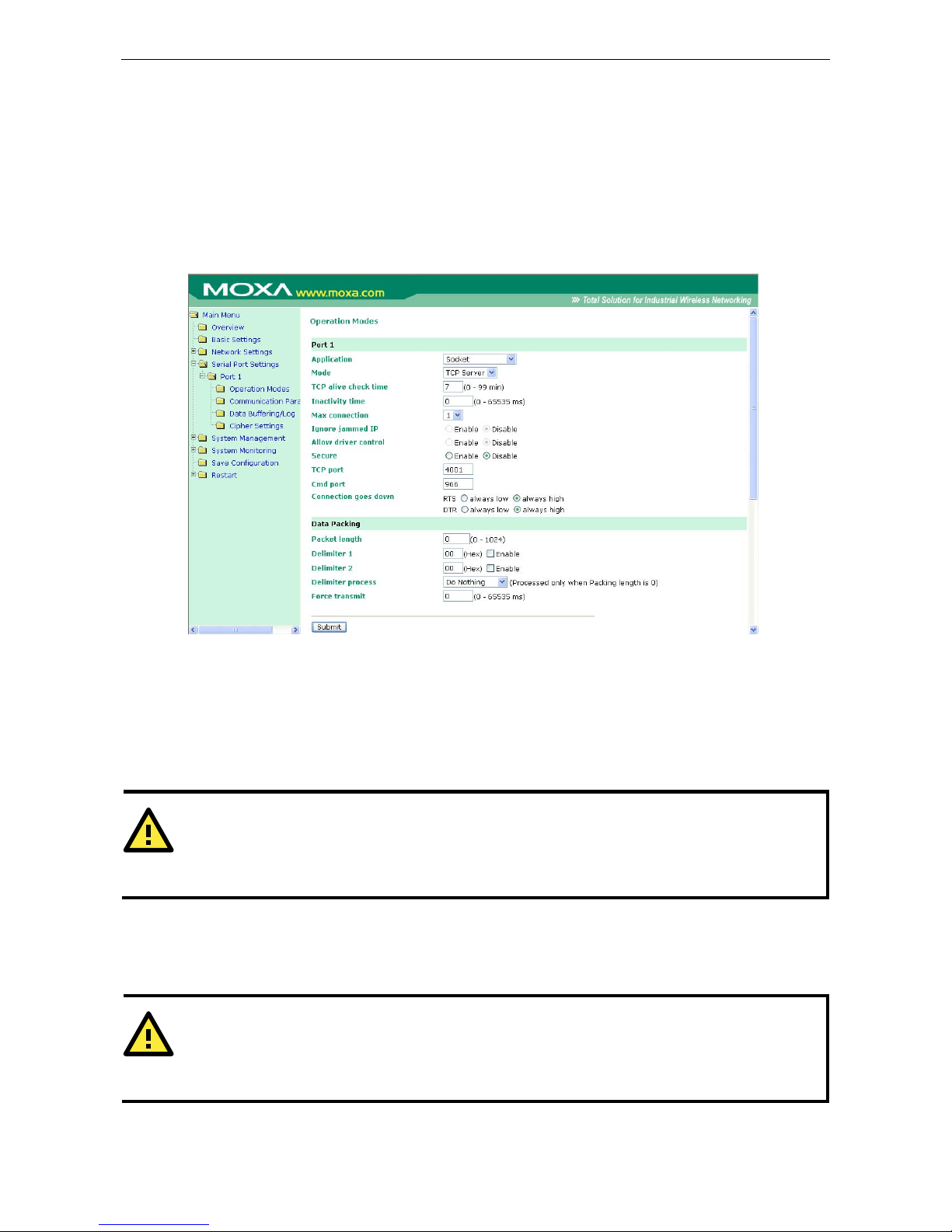
OnCell G3100 Series Configuring Serial Port Operation Modes
8-9
If it is necessary to send a series of characters in the same packet, the serial device will need to send that series
of characters within the specified force transmit time, and the total length of data must be less than or equal
to the OnCell G3100’s internal buffer size (1 KB per port).
Socket Applications
TCP Server Mode
TCP alive check time (default=7 min): This field specifies how long the OnCell G3100 will wait for a response
to “keep alive” packets before closing the TCP connection. The OnCell G3100 checks connection status by
sending periodic “keep alive” packets. If the remote host does not respond to the packet within the time
specified in this field, the OnCell G3100 will force the existing TCP connection to close. For socket and device
control modes, the OnCell G3100 will listen for another TCP connection from another host after closing the
connection. If TCP alive check time is set to 0, the TCP connection will remain open even if there is no
response to the “keep alive” packets.
ATTENTION
You should make sure the inactivity time v a lue used here is less than the inactivity ti me value on the
GSM/GPRS configuration page. The GSM/GPRS connection must be maintained in order to achieve the
inactivity time behavior of the TCP connection.
Inactivity time (default=0 ms): This field specifies how long the OnCell G3100 will wait for incoming and
outgoing data through the serial port before closing the TCP connection. The TCP connection is closed if there
is no incoming or outgoing data through the serial port for the specified Inactivity time. If this field is set to
0, the TCP connection is kept active until a connection close request is received.
ATTENTION
If used, the Inactivity time setting should be greater than the Force transmit time. To prevent the
unintended loss of data due to the session being disconnected, it is highly recommended that this value is set
large enough so that the intended data transfer is completed.
Max connection (default=1): This field is used if you need to receive data from different hosts
simultaneously. When set to 1, only a single host may open the TCP connection to the serial port. When set to
Page 70

OnCell G3100 Series Configuring Serial Port Operation Modes
8-10
2, the specified number of hosts may open this port at th e same time. When multiple hosts establish a TCP
connection to the serial port at the same time, the OnCell G3100 will duplicate the serial data and transmit it
to all the hosts. Cellular or Ethernet data is sent on a first-in first-out basis to the serial port when data comes
into the OnCell G3100 from the Cellular or Ethernet interface.
Ignore jammed IP (default=Disable): This option determines how the port will proceed if multiple hosts are
connected and one or more of the hosts stops responding as the port is transmitting data. If you select Disable,
the port will wait until the data has been transmitted successfully to all hosts before transmitting the next group
of data. If you select Enable, the port will ignore the host that stopped responding and continue data
transmission to the other hosts.
Allow driver control (default=Disable): This option determines how the port will proceed if driver control
commands are received from multiple hosts that are connected to the port. If Disable is selected, driver
control commands will be ignored. If Enable is selected, control commands will be accepted, with the most
recent command received taking precedence.
Secure (default=Disable): If you select Enable, data sent through the Ethernet will be encrypted with SSL.
TCP port (default=4001): This is the TCP port number assignment for the serial port on the OnCell G3100. It
is the port number that the serial port uses to listen to connections, and that other devices must use to contact
the serial port. To avoid conflicts with well known TCP port s, the default is set to 4001.
Command port (default=966): The Command port is the TCP port for listening to SSDK commands from the
host. In order to prevent a TCP port conflict with other applications, the user can set the Command port to
another port if needed.
Packet length (default=0): The Packet length setting refers to the maximum amount of data that is allowed
to accumulate in the serial port buffer before sending. At the default of 0 for packet length, no maximum
amount is specified and data in the buffer will be sent as specified by the delimiter settings or when the buffer
is full. When a packet length between 1 and 1024 bytes is specified, data in the buffer will be sent as soon it
reaches the specified length.
Delimiter 1 and Delimiter 2 (default=None): When Delimiter 1 is enabled, the serial port will clear the buffer
and send the data to the Ethernet port when a specific character, entered in hex format, is received. A second
delimiter character may be enabled and specified in the Delimiter 2 field, so that both characters act as the
delimiter to indicate when data should be sent.
ATTENTION
In order to enable a delimiter, packet length must be set to 0. Delimiter 2 should only be enabled in
conjunction with Delimiter 1 and never on its own; otherwise there may be data errors. Even when a delimiter
is enabled, the OnCell G3100 will still pack and send the data when the amount of data exceeds 1 KB.
Delimiter process (default=Do Nothing): The Delimiter process field determines how the data is handled
when a delimiter is received. Delimiter 1 must be enabled for this field to have effect. If Delimiters 1 and 2 are
both enabled, both characters must be received for the delimiter process to take place.
• Do Nothing: Data in the buffer will be transmitted when the delimiter is received.
• Delimiter + 1: Data in the buffer will be transmitted after 1 additional byte is received following the
delimiter.
• Delimiter + 2: Data in the buffer will be transmitted after 2 additional bytes are received following the
delimiter.
• Strip Delimiter: Data in the buffer is first stripped of the delimiter before being transmitted.
Force transmit (default=0 ms): This parameter defines how larg e a gap in serial communication the OnCell
G3100 will allow before packing the serial data in its internal buffer for network transmission.
As data is received through the serial port, it is stored by the OnCell G3100 in the internal buffer. The OnCell
G3100 transmits data stored in the buffer via TCP/IP, but only when the internal buffer is full or as specified by
the force transmit time. When set to 0, the force transmit time is disabled, and transmission is determined
Page 71
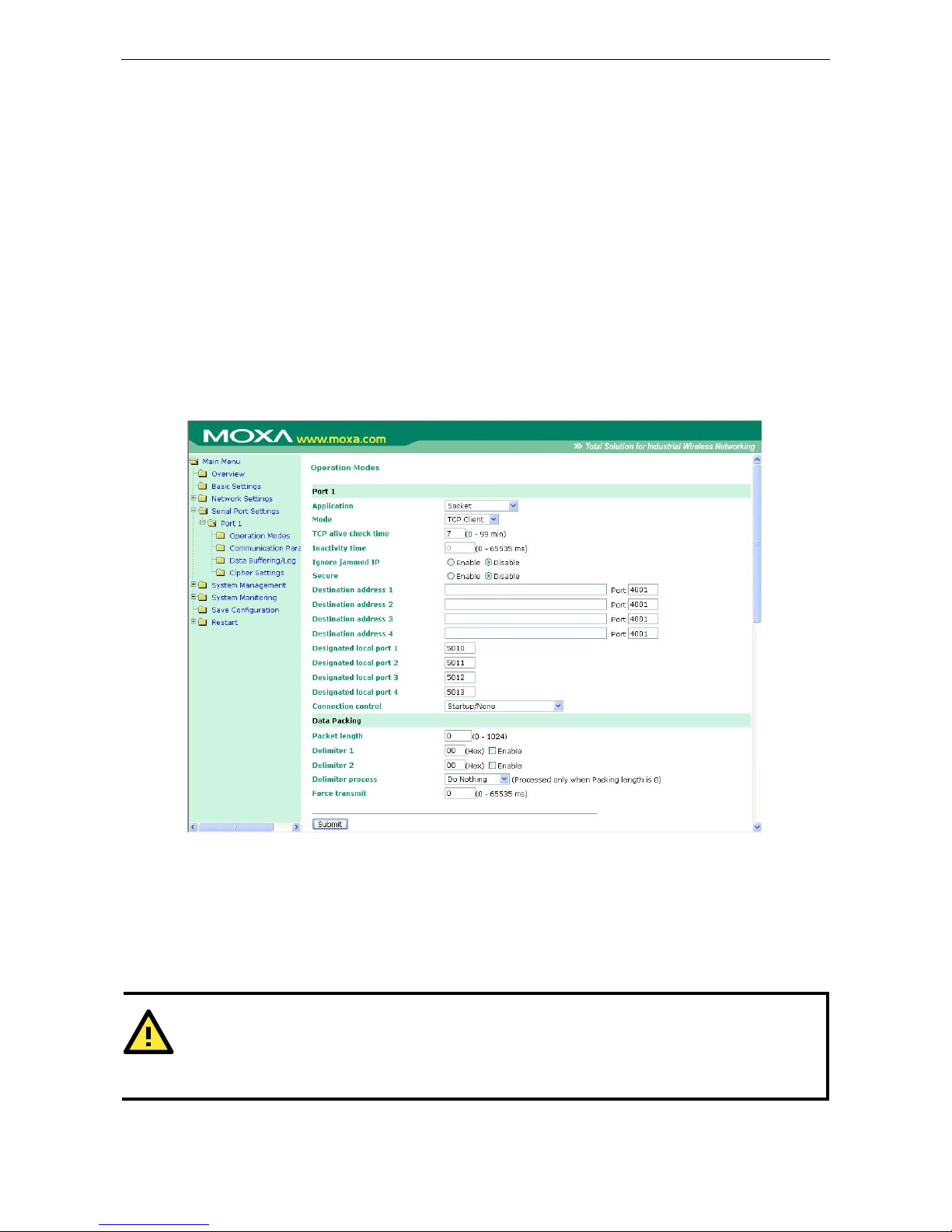
OnCell G3100 Series Configuring Serial Port Operation Modes
8-11
solely by the data in the internal buffer. At 1 to 65535, the TCP/IP protocol software will pack the serial data
received after there is a gap in serial communication that exceeds the specified force transmit time.
The optimal force transmit time depends on your application, but it must be at least larger than one character
interval within the specified baudrate. For example, assume that the se rial port is set to 1200 bps, 8 dat a bits,
1 stop bit, and no parity. In this case, the total number of bits needed to send a character is 10 bits, and the
time required to transfer one character is
(10 (bits) / 1200 (bits/s)) × 1000 (ms/s) = 8.3 ms.
Therefore, you should set the force transmit time to be larger than 8.3 ms, so in this case, it must be greater
than or equal to 10 ms.
If it is necessary to send a series of characters in the same packet, the serial device will need to send that series
of characters within the specified force transmit time, and the total length of data must be less than or equal
to the OnCell G3100’s internal buffer size (1 KB per port).
TCP Client Mode
TCP alive check time (default=7 min): This field specifies how long the OnCell G3100 will wait for a response
to “keep alive” packets before closing the TCP connection. The OnCell G3100 checks connection status by
sending periodic “keep alive” packets. If the remote host does not respond to the packet within the time
specified in this field, the OnCell G3100 will force the existing TCP connection to close. For socket and device
control modes, the OnCell G3100 will listen for another TCP connection from another host after closing the
connection. If TCP alive check time is set to 0, the TCP connection will remain open even if there is no
response to the “keep alive” packets.
ATTENTION
You should make sure the inactivity time v a lue used here is less than the inactivity ti me value on the
GSM/GPRS configuration page. The GSM/GPRS connection must be maintained in order to achieve the
inactivity time behavior of the TCP connection.
Inactivity time (default=0 ms): This field specifies how long the OnCell G3100 will wait for incoming and
outgoing data through the serial port before closing the TCP connection. The TCP connection is closed if there
Page 72
OnCell G3100 Series Configuring Serial Port Operation Modes
8-12
is no incoming or outgoing data through the serial port for the specified Inactivity time. If this field is set to
0, the TCP connection is kept active until a connection close request is received.
ATTENTION
If used, the Inactivity time setting should be greater than the Force transmit time. To prevent the
unintended loss of data due to the session being disconnected, it is highly recommended that this v alue is set
large enough so that the intended data transfer is completed.
ATTENTION
Inactivity time is ONLY active when Connection Control (see below) is set to Any character/Inactivity
time.
Ignore jammed IP (default=Disable): This option determines how the port will proceed if multiple hosts are
connected and one or more of the hosts stops responding as the port is transmitting data. If you select Disable,
the port will wait until the data has been transmitted successfully to all hosts before transmitting the next group
of data. If you select Enable, the port will ignore the host that stopped responding and continue data
transmission to the other hosts.
Secure (default=Disable): If you select Enable, data sent through the Ethernet will be encrypted with SSL.
Destination address 1 through 4 (default=None): Specifying an IP address allows the OnCell G3100 to
connect actively to the remote host. At least one destination must be provided.
TCP port (default=4001): This is the TCP port number assignment for the serial port on the OnCell G3100. It
is the port number that the serial port uses to make a connection, and that serial port must use to contact the
other devices. To avoid conflicts with well known TCP ports, the default is set to 4001.
ATTENTION
Up to 4 connections can be established between the OnCell G3100 and hosts. The connection speed or
throughput may be low if any one of the four connections is slow, since the one slow connection will slow down
the other 3 connections.
ATTENTION
The Destination IP address parameter can be the IP address, domain name, or the name defined in the host
table. For some applications, the user may need to send the data actively to the remote destination domain
name.
Designated local port 1 through 4 (default=5010 through 5013): Us e these fields t o specify the desi gnated
local ports.
Connection control (default=Startup/None): This setting determines the parameters under which a TCP
connection is established or disconnected. The different options are given in the following table. In general,
both the Connect condition and Disconnect conditions are given .
Option Description
Startup/None (default) A TCP connection will be established on startup, and will remain active indefinitely.
Any Character/None A TCP connection will be established when any character is received from the serial
interface, and will remain active indefinitely.
Any Character/
Inactivity Time
A TCP connection will be established when any character is received from the serial
interface, and will be disconnected when Inactivity time is reached.
DSR On/DSR Off A TCP connection will be established when a DSR signal of OnCell is “On”, and will
remain active indefinitely.
Page 73
OnCell G3100 Series Configuring Serial Port Operation Modes
8-13
DSR On/None A TCP connection will be established when a DSR “On” signal is received, and will
remain active indefinitely.
DCD On/DCD Off A TCP connection will be established when a DCD signal of OnCell is “On”, and will
remain active indefinitely.
DCD On/None A TCP connection will be establishe d when a DCD “On” signal is received, and will
remain active indefinitely.
Packet length (default=0): This field refers to the maximum amount of data that is allowed to accumulate in
the serial port buffer before sending. At the default of 0 for packet length, no maximum amount is specified and
data in the buffer will be sent as specified by the delimiter settings or when the buffer is full. When a packet
length between 1 and 1024 bytes is specified, data in the buffer will be sent as soon it reaches the specified
length.
Delimiter 1 and Delimiter 2 (default=None): When Delimiter 1 is enabled, the serial port will clear the buffer
and send the data to the Ethernet port when a specific character, entered in hex format, is received. A second
delimiter character may be enabled and specified in the Delimiter 2 field, so that both characters act as the
delimiter to indicate when data should be sent.
ATTENTION
In order to enable a delimiter, packet length must be set to 0. Delimiter 2 should only be enabled in
conjunction with Delimiter 1 and never on its own; otherwise there may be data errors. Even when a delimiter
is enabled, the OnCell G3100 will still pack and send the data when the amount of data exceeds 1 KB.
Delimiter process (default=Do Nothing): The Delimiter process field determines how the data is handled
when a delimiter is received. Delimiter 1 must be enabled for this field to have effect. If Delimiters 1 and 2 are
both enabled, both characters must be received for the delimiter process to take place.
• Do Nothing: Data in the buffer will be transmitted when the delimiter is received.
• Delimiter + 1: Data in the buffer will be transmitted after 1 additional byte is received following the
delimiter.
• Delimiter + 2: Data in the buffer will be transmitted after 2 additional bytes are received following the
delimiter.
• Strip Delimiter: Data in the buffer is first stripped of the delimiter before being transmitted.
Force transmit (default=0 ms): This parameter defines how larg e a gap in serial communication the OnCell
G3100 will allow before packing the serial data in its internal buffer for network transmission.
As data is received through the serial port, it is stored by the OnCell G3100 in the internal buffer. The OnCell
G3100 transmits data stored in the buffer via TCP/IP, but only when the internal buffer is full or as specified by
the force transmit time. When set to 0, the force transmit time is disabled, and transmission is determined
solely by the data in the internal buffer. At 1 to 65535, the TCP/IP protocol software will pack the serial data
received after there is a gap in serial communication that exceeds the specified force transmit time.
The optimal force transmit time depends on your application, but it must be at least larger than one character
interval within the specified baudrate. For example, assume that the se rial port is set to 1200 bps, 8 dat a bits,
1 stop bit, and no parity. In this case, the total number of bits needed to send a character is 10 bits, and the
time required to transfer one character is
(10 (bits) / 1200 (bits/s)) × 1000 (ms/s) = 8.3 ms.
Therefore, you should set the force transmit time to be larger than 8.3 ms, so in this case, it must be greater
than or equal to 10 ms.
If it is necessary to send a series of characters in the same packet, the serial device will need to send that series
of characters within the specified force transmit time, and the total length of data must be less than or equal
to the OnCell G3100’s internal buffer size (1 KB per port).
Page 74

OnCell G3100 Series Configuring Serial Port Operation Modes
8-14
UDP Mode
Destination address 1 through 4 (default=None): In UDP mode, you may spec ify up to 4 ranges of IP
addresses for the serial port to connect to. At least one destination range must be provided.
ATTENTION
The maximum selectable IP address range is 64 addresses. However, when using multicast, you may enter IP
addresses of the form xxx.xxx.xxx.255 in the Begin field. For example, enter 192.168.127.255 to allow the
OnCell G3100 to broadcast UDP packets to all hosts with IP addresses between 192.168.127.1 and
192.168.127.254.
Local listen port (default=4001): This is the UDP port that the OnCell G3100 listens to and that other devices
must use to contact the OnCell G3100. To avoid conflicts with well known UDP ports, the default is set to 4001.
Packet length (default=0): The Packet length setting refers to the maximum amount of data that is allowed
to accumulate in the serial port buffer before sending. At the default of 0 for packet length, no maximum
amount is specified and data in the buffer will be sent as specified by the delimiter settings or when the buffer
is full. When a packet length between 1 and 1024 bytes is specified, data in the buffer will be sent as soon it
reaches the specified length.
Delimiter 1 and Delimiter 2 (default=None): When Delimiter 1 is enabled, the serial port will clear the buffer
and send the data to the Ethernet port when a specific character, entered in hex format, is received. A second
delimiter character may be enabled and specified in the Delimiter 2 field, so that both characters act as the
delimiter to indicate when data should be sent.
ATTENTION
In order to enable a delimiter, packet length must be set to 0. Delimiter 2 should only be enabled in
conjunction with Delimiter 1 and never on its own; otherwise there may be data errors. Even when a delimiter
is enabled, the OnCell G3100 will still pack and send the data when the amount of data exceeds 1 KB.
Delimiter process (default=Do Nothing): The Delimiter process field determines how the data is handled
when a delimiter is received. Delimiter 1 must be enabled for this field to have effect. If Delimiters 1 and 2 are
both enabled, both characters must be received for the delimiter process to take place.
• Do Nothing: Data in the buffer will be transmitted when the delimiter is received.
• Delimiter + 1: Data in the buffer will be transmitted after 1 additional byte is received following the
delimiter.
• Delimiter + 2: Data in the buffer will be transmitted after 2 additional bytes are received following the
delimiter.
Page 75

OnCell G3100 Series Configuring Serial Port Operation Modes
8-15
• Strip Delimiter: Data in the buffer is first stripped of the delimiter before being transmitted.
Force transmit (default=0 ms): This parameter defines how larg e a gap in serial communication the OnCell
G3100 will allow before packing the serial data in its internal buffer for network transmission.
As data is received through the serial port, it is stored by the OnCell G3100 in the internal buffer. The OnCell
G3100 transmits data stored in the buffer via TCP/IP, but only when the internal buffer is full or as specified by
the force transmit time. When set to 0, the force transmit time is disabled, and transmission is determined
solely by the data in the internal buffer. At 1 to 65535, the TCP/IP protocol software will pack the serial data
received after there is a gap in serial communication that exceeds the specified force transmit time.
The optimal force transmit time depends on your application, but it must be at least larger than one character
interval within the specified baudrate. For example, assume that the se rial port is set to 1200 bps, 8 dat a bits,
1 stop bit, and no parity. In this case, the total number of bits needed to send a character is 10 bits, and the
time required to transfer one character is
(10 (bits) / 1200 (bits/s)) × 1000 (ms/s) = 8.3 ms.
Therefore, you should set the force transmit time to be larger than 8.3 ms, so in this case, it must be greater
than or equal to 10 ms.
If it is necessary to send a series of characters in the same packet, the serial device will need to send that series
of characters within the specified force transmit time, and the total length of data must be less than or equal
to the OnCell G3100’s internal buffer size (1 KB per port).
Ethernet Modem Mode
The OnCell G3100 accepts the AT command ATD IP address:TCP port (for example, ATD
192.168.127.1:4001) from the serial port and then requests a TCP connection from the remote Ethernet
Modem or PC. Here IP address is the IP address of the remote Ethernet modem or PC, and TCP port is the TCP
port number of the remote Ethernet modem or PC. Once the remote unit accepts this TCP connection, the
OnCell G3100 will send out the “CONNECT baud” signal via the serial port and then enter data mode.
TCP alive check time (default=7 min): This field specifies how long the OnCell G3100 will wait for a response
to “keep alive” packets before closing the TCP connection. The OnCell G3100 checks connection status by
sending periodic “keep alive” packets. If the remote host does not respond to the packet within the time
specified in this field, the OnCell G3100 will force the existing TCP connection to close. For socket and device
control modes, the OnCell G3100 will listen for another TCP connection from another host after closing the
connection. If TCP alive check time is set to 0, the TCP connection will remain open even if there is no
response to the “keep alive” packets.
Page 76

OnCell G3100 Series Configuring Serial Port Operation Modes
8-16
TCP port (default=4001): This is the TCP port number assignment for the serial port on the OnCell G3100. It
is the port number that the serial port uses to listen to connections, and that other devices must use to contact
the serial port. To avoid conflicts with well known TCP port s, the default is set to 4001.
Dial-in
The OnCell G3100 listens for a TCP/IP connection request from the remote Ethernet modem or host. The OnCell
G3100’s response depends on the ATS0 value, as follows.
ATS0=0:
The OnCell G3100 will temporarily accept the TCP connection and then send the RING signal out through the
serial port. The serial controller must reply with ATA within 2.5 seconds to accept the connection request, after
which the OnCell G3100 enters data mode. If no ATA command is received, the OnCell G3100 will disconnect
after sending three RING signals.
ATS0≧1:
The OnCell G3100 will accept the TCP connection immediately and then send the “CONNECT baud” command
to the serial port, in which baud represents the baudrate of the OnCell G3100’s serial port. After that, the
OnCell G3100 immediately enters data mode.
Dial-out
The OnCell G3100 accepts the AT command “ATD IP:TCP port” from the serial port and then requests a TCP
connection from the remote Ethernet Modem or PC. Here IP is the IP address of the remote Ethernet modem
or PC, and TCP port is the TCP port number of the remote Ethernet modem or PC. Once the remote unit accepts
this TCP connection, the OnCell G3100 will send out the CONNECT baud” signal via the serial port and then
enter data mode.
Disconnection request from local site
When the OnCell G3100 is in data mode, the user can initiate disconnection by sending “+++” from the local
serial port to the OnCell G3100. Some applications allow you to s et the DTR signal to off, which will also ini tiate
disconnection. The OnCell G3100 will enter command mode, and after 1 second, you can then enter ATH to
shut down the TCP connection. The OnCell G3100 will return a NO CARRIER via the serial port.
NOTE The “+++” command cannot be divided. The “+” character can be changed in register S2, and the guard time,
which prefixes and suffixes the “+++” in order to protect the raw data, can be changed in register S12.
Disconnection request from remote site
After the TCP connection has been shut down by the remote Ethernet modem or PC, the OnCell G3100 will send
the NO CARRIER signal via the serial port and then return to command mode.
AT Commands
The OnCell G3100 supports the following common AT commands as used with a typical modem:
No. AT command Description Remarks
1 ATA Answer manually
2 ATD <IP>:<Port> Dial up the IP address : Port No.
3 ATE ATE0=Echo OFF
ATE1=Echo ON (default)
Page 77

OnCell G3100 Series Configuring Serial Port Operation Modes
8-17
4 ATH ATH0=On-hook (default)
ATH1=Off-hook
5 ATI, ATI0, ATI1, ATI2 Modem version reply “OK” only
6 ATL Speaker volume option reply “OK” only
7 ATM Speaker control option reply “OK” only
8 ATO On line command
9 ATP, ATT Set Pulse/Tone Dialing mode reply “OK” only
10 ATQ0, ATQ1 Quiet command (default=ATQ0)
11 ATSr=n Change the contents of S register See “S registers”
12 ATSr? Read the contents of S register See “S registers”
13 ATV Result code type
ATV0 for digit code,
ATV1 for text code (default)
0=OK
1=connect
2=ring
3=No carrier
4=error
14 ATZ Reset (disconnect, enter command mode and
restore the flash settings)
15 AT&C Serial port DCD control
AT&C0=DCD always on
AT&C1=DTE detects connection by DCD on/off
(default)
16 AT&F Restore manufacturer’s settings
17 AT&G Select guard time reply “OK” only
18 AT&R Serial port RTS option command reply “OK” only
19 AT&S Serial port DSR control reply “OK” only
20 AT&V View settings
21 AT&W Write current settings to flash for next boot up
S Registers
No. S Register Description & default value Remarks
1 S0 Ring to auto-answer (default=0)
2 S1 Ring counter (always=0) no action applied
3 S2 Escape code character (default=43 ASCII “+”)
4 S3 Return character (default=13 ASCII)
5 S4 Line feed character (default=10 ASCII)
6 S5 Backspace character (default= 8 ASCII)
7 S6 Wait time for dial tone (always=2, unit=sec) no action applied
8 S7 Wait time for carrier (default=3, unit=sec)
9 S8 Pause time for dial delay (always=2, unit=sec) no action applied
10 S9 Carrier detect response time
(always=6, unit 1/10 sec)
no action applied
11 S10 Delay for hang up after carrier
(always=14, unit 1/10 sec)
no action applied
12 S11 DTMF duration and spacing
(always=100 ms)
no action applied
13 S12 Escape code guard time
(default=50, unit 1/50 sec)
to control the idle time for “+++”
Page 78

OnCell G3100 Series Configuring Serial Port Operation Modes
8-18
SMS Tunnel Mode
SMS IN enable (default=Disable): To allow forwarding incoming short message to the OnCell G3100’s s erial
port as data.
Auth type (default=none): To allow Caller ID Authentication
Caller ID (1 through 4): Phone number should be specified.
SMS OUT enable (default=Disable): To allow data received from the attached serial dev ic es to be
transmitted as short messages.
Target Phone Number (1 through 4): Phone number should be specified.
Encode Format
SMS Data Format
Text ASCII (7 bits) (default) 7-bit text format (160 bytes per packet)
Binary 8-bit binary (140 bytes per packet)
Unicode 16-bit Unicode (UCS2) format (70 bytes per packet)
ATTENTION
The Target Phone Number must be specified if SMS-OUT is activated.
The Target Phone Number and Caller ID can be written in either international format, starting with “+”
followed by the country code, or loca l format, starting with local area code.
If you don’t use Caller ID authentication, the OnCell G3100 will allow all incoming short messages as serial
data to be forwarded to its serial port. This includes system broadcasts and advertisements.
Packet length (default=0): The Packet length setting refers to the maximum amount of data that is allowed
to accumulate in the serial port buffer before sending. At the default of 0 for packet length, no maximum
amount is specified and data in the buffer will be sent as specified by the delimiter settings or when the buffer
is full. When a packet length between 1 and 160 bytes is specified, data in the buffer will be sent as soon it
reaches the specified length.
Page 79

OnCell G3100 Series Configuring Serial Port Operation Modes
8-19
Delimiter 1 and Delimiter 2 (default=None): When Delimiter 1 is enabled, the serial port will queue the data
in the buffer and send the data to the Cellular or Ethernet port when a specific character, entered in hex format,
is received. A second delimiter character may be enabled and specified in the Delimiter 2 field, so that both
characters act as the delimiter to control when data should be sent.
ATTENTION
In order to enable a delimiter, packet length must be set to 0. Delimiter 2 should only be enabled in
conjunction with Delimiter 1 and never on its own; otherwise there may be data errors. Even when a delimiter
is enabled, the OnCell G3100 will still pack and send the data when the amount of data exceeds 1 KB.
Delimiter process (default=Do Nothing): The Delimiter process field determines how the data is handled
when a delimiter is received. Delimiter 1 must be enabled for this field to have effect. If Delimiters 1 and 2 are
both enabled, both characters must be received for the delimiter process to take place.
• Do Nothing: Data in the buffer will be transmitted when the delimiter is received.
• Delimiter + 1: Data in the buffer will be transmitted after 1 additional byte is received following the
delimiter.
• Delimiter + 2: Data in the buffer will be transmitted after 2 additional bytes are received following the
delimiter.
• Strip Delimiter: Data in the buffer is first stripped of the delimiter before being transmitted.
Force transmit (default=0 ms): This parameter defines how larg e a gap in serial communication the OnCell
G3100 will allow before packing the serial data in its internal buffer for network transmission.
As data is received through the serial port, it is stored by the OnCell G3100 in the internal buffer. The OnCell
G3100 transmits data stored in the buffer via SMS, but only when the internal buffer is full or as specified by
the force transmit time. When set to 0, the force transmit time is disabled, and transmission is determined
solely by the data in the internal buffer. At 1 to 65535, the SMS protocol software will pack the serial data
received after there is a gap in serial communication that exceeds the specified force transmit time.
The optimal force transmit time depends on your application, but it must be at least larger than one character
interval within the specified baudrate. For example, assume that the se rial port is set to 1200 bps, 8 dat a bits,
1 stop bit, and no parity. In this case, the total number of bits needed to send a character is 10 bits, and the
time required to transfer one character is
(10 (bits) / 1200 (bits/s)) × 1000 (ms/s) = 8.3 ms.
Therefore, you should set the force transmit time to be larger than 8.3 ms, so in this case, it must be greater
than or equal to 10 ms.
If it is necessary to send a series of characters in the same packet, the serial device will need to send that series
of characters within the specified force transmit time, and the total length of data must be less than or equal
to the OnCell G3100’s internal buffer size.
Page 80

OnCell G3100 Series Configuring Serial Port Operation Modes
8-20
Disabled Mode
When the Application is set to Disable, the relevant port will be disabled.
Page 81

9
9. Configuring the Cellular-Enabling Ethernet
Device
In this chapter, we explain how to configure the Cellular-enabling Ethernet device.
Note: This function only support in OnCell G3100 Rev. 2.0, please refer Chapter 1 Specification page
1-3 for more information.
The following topics are covered in this chapter:
Host to OnCell via Cellular
OnCell to Host via Cellular
Page 82
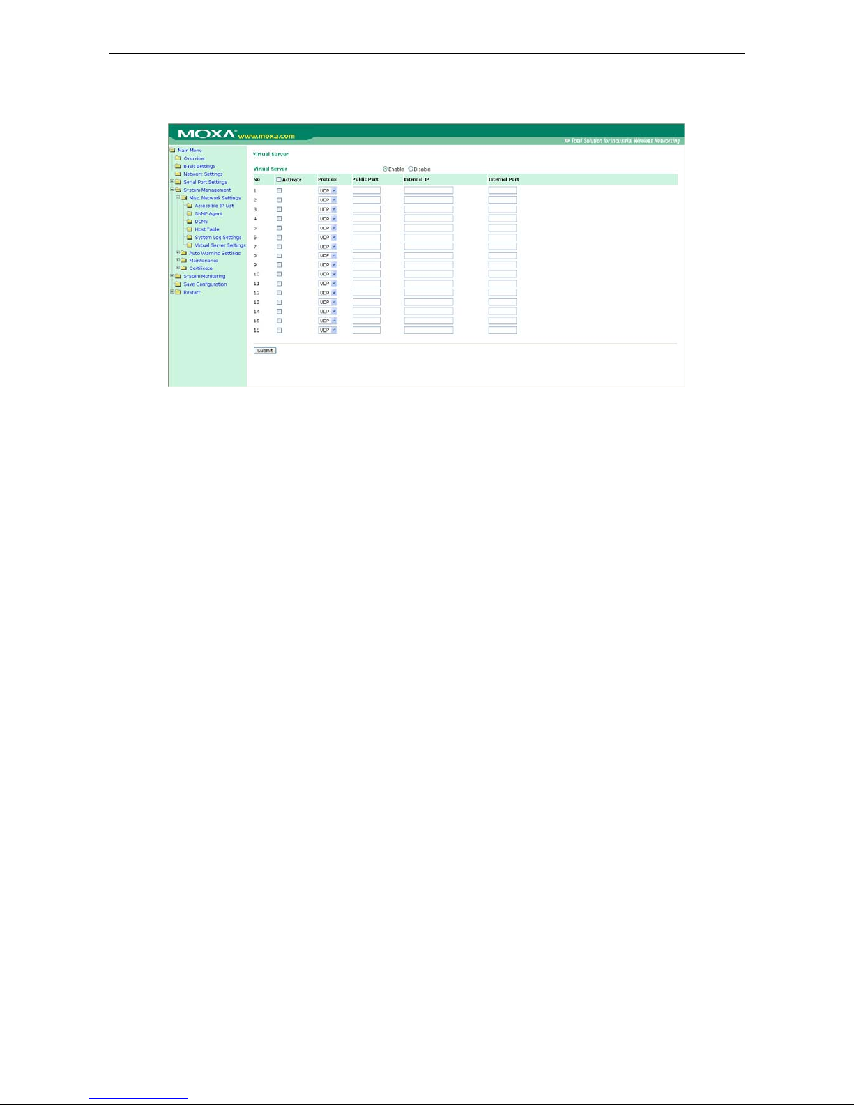
OnCell G3100 Series Configuring the Cellular-Enabling Ethernet Device
9-2
Host to OnCell via Cellular
Virtual Server Settings (default=Disable): This function allows re mote users to access the Host or FTP
services via a public IP address, and automatically redirects them to loca l servers in the LAN (Local Area
Network).
The OnCell firewall feature filters out unrecognized packets to protect your LAN network when computers
networked with the OnCell are hidden from public view. If you wish, you can make some of the LAN computers
accessible from the Internet by enabling Virtual Server. Depending on the requested service, the OnCell
redirects the external service request to the appropriate server within the LAN network.
The OnCell is also capable of port-redirection meaning incoming traffic to a particular port may be redirected to
a different port on the server computer.
Public Port: The public port is the port seen from the Internet side. Public ports cannot be set to ports used by
OP modes (950, 966, 4001, …)
Internal IP: Enter the IP address of the host on your local network that you want to link the incoming service
to.
Internal Port: The internal port is the port being used by the application on the host within your local network.
OnCell to Host via Cellular
This section explains the configuration for when the Ethernet device acts as the Client. In order for the Ethernet
device to send data to the host, it must set the OnCell as a gateway. This function will automatically detect the
OnCell’s IP address by DHCP enable (default=enable) Please refer page 58 for DHCP function explaination.
Alternatively, you can manually ent er the I nternet Pr otoc ol ( TCP/I P) propert i es, an d DNS se rver addresses in
the Ethernet device.
Page 83
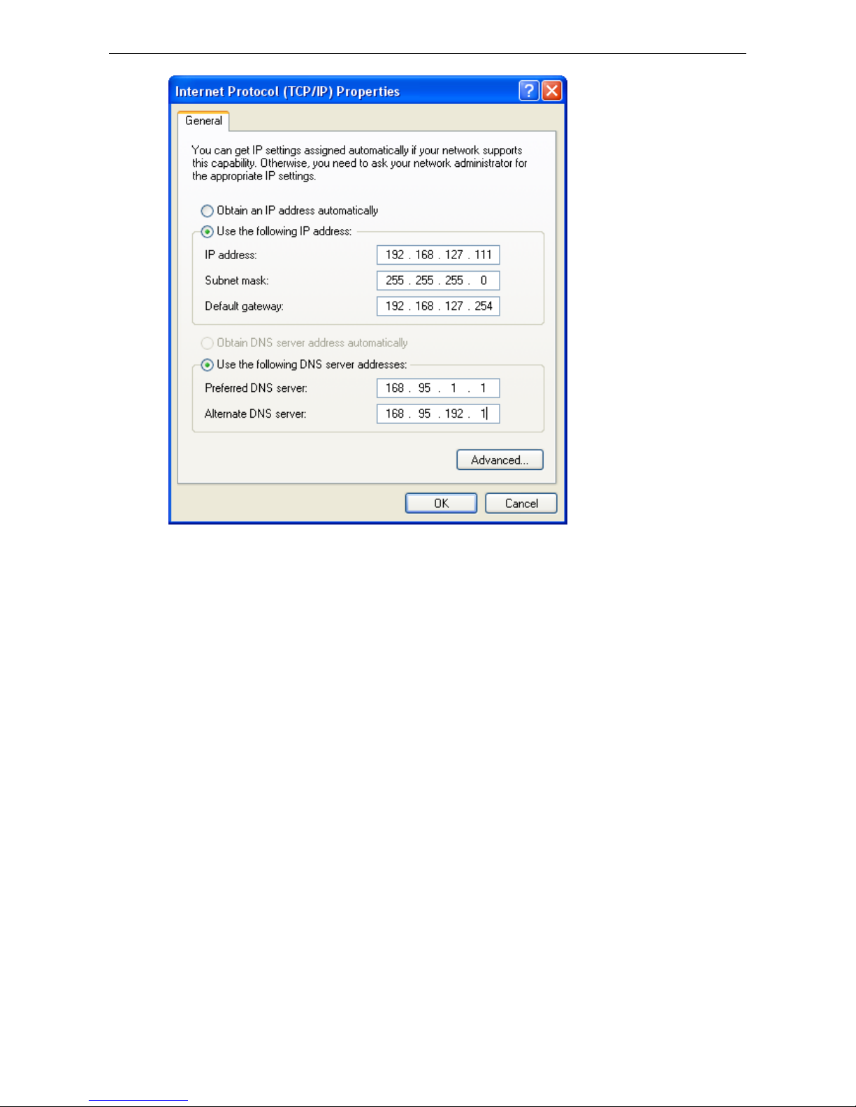
OnCell G3100 Series Configuring the Cellular-Enabling Ethernet Device
9-3
Page 84

10
10. Configuring Virtual Modem Mode
In this chapter, we explain how to configure Virtual Modem Mode for running AT command operating system
devices. This operation mode is available for CSD, SMS and GPRS cellular services. Before starting
configuration, you will need to select the appropriate cellular service because different cellular services have
different software installation methods.
Note: This function is only supported by the OnCell G3100 Rev. 2.0. Please refer to the
Specifications section of Chapter 1 (page 1-3) for more information.
The following topics are covered in this chapter:
OnCell G3100 Web Settings
¾ Install Windows Driver Manager
¾ Using OnCell Windows Driver Manager
¾ Using PComm for Data Transmission
CSD via AT command
SMS via AT command
GPRS via AT command
GPRS via Windows Dia
l
-up Network
Page 85

OnCell G3100 Series Configuring Virtual Modem Mode
10-2
OnCell G3100 Web Settings
From the left navigation panel, click Network Settings →GSM GPRS Settings to enable Virtual Modem
Settings. The configuration items are described below:
Install Windows Driver Manager
Windows Driver Manager should be insta ll ed for all cellular connections.
1. Click the INSTALL COM Driver button in the OnCell Installation CD auto-run window to install the OnCell
Windows Driver. Once the installation program starts running, click Yes to proceed.
2. Click Next when the Welcome screen opens to proceed with the installation.
Page 86
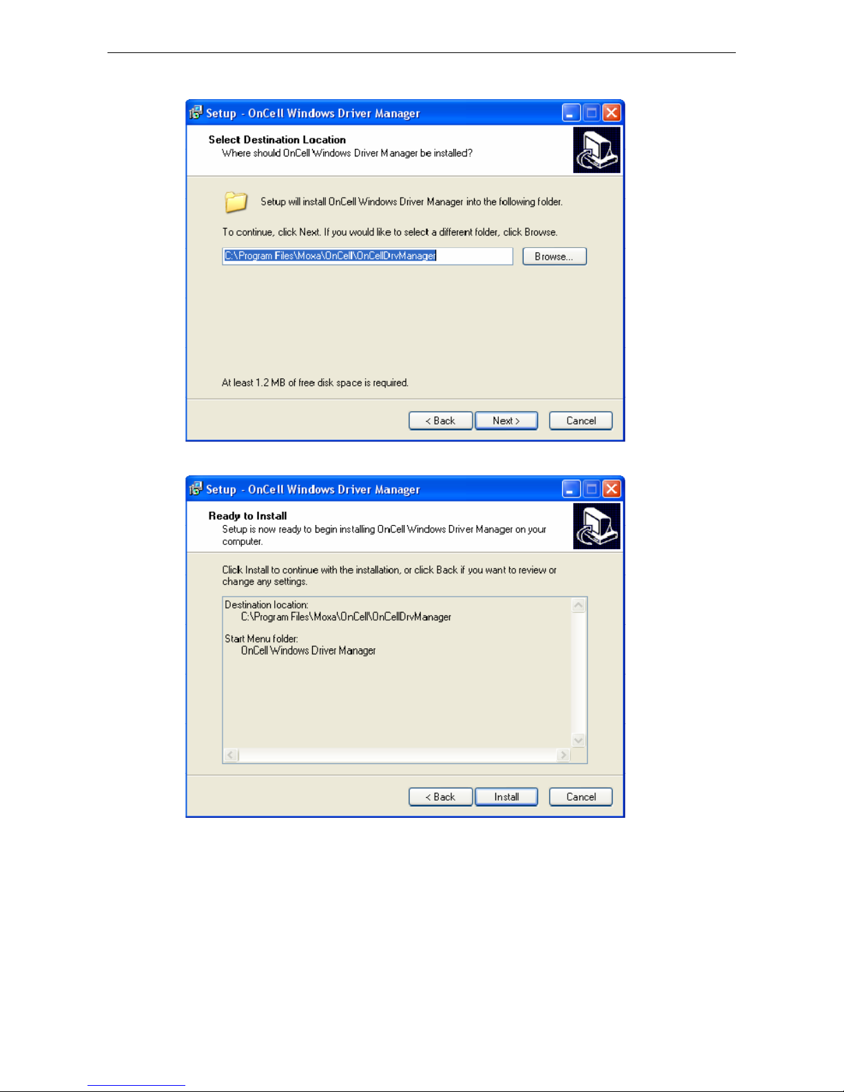
OnCell G3100 Series Configuring Virtual Modem Mode
10-3
3. Click Next to install program files to the default directory, or click Browse to select an alternate location.
4. The Setup window will display a summary of the installation options. Click Install to begin the installation.
Page 87
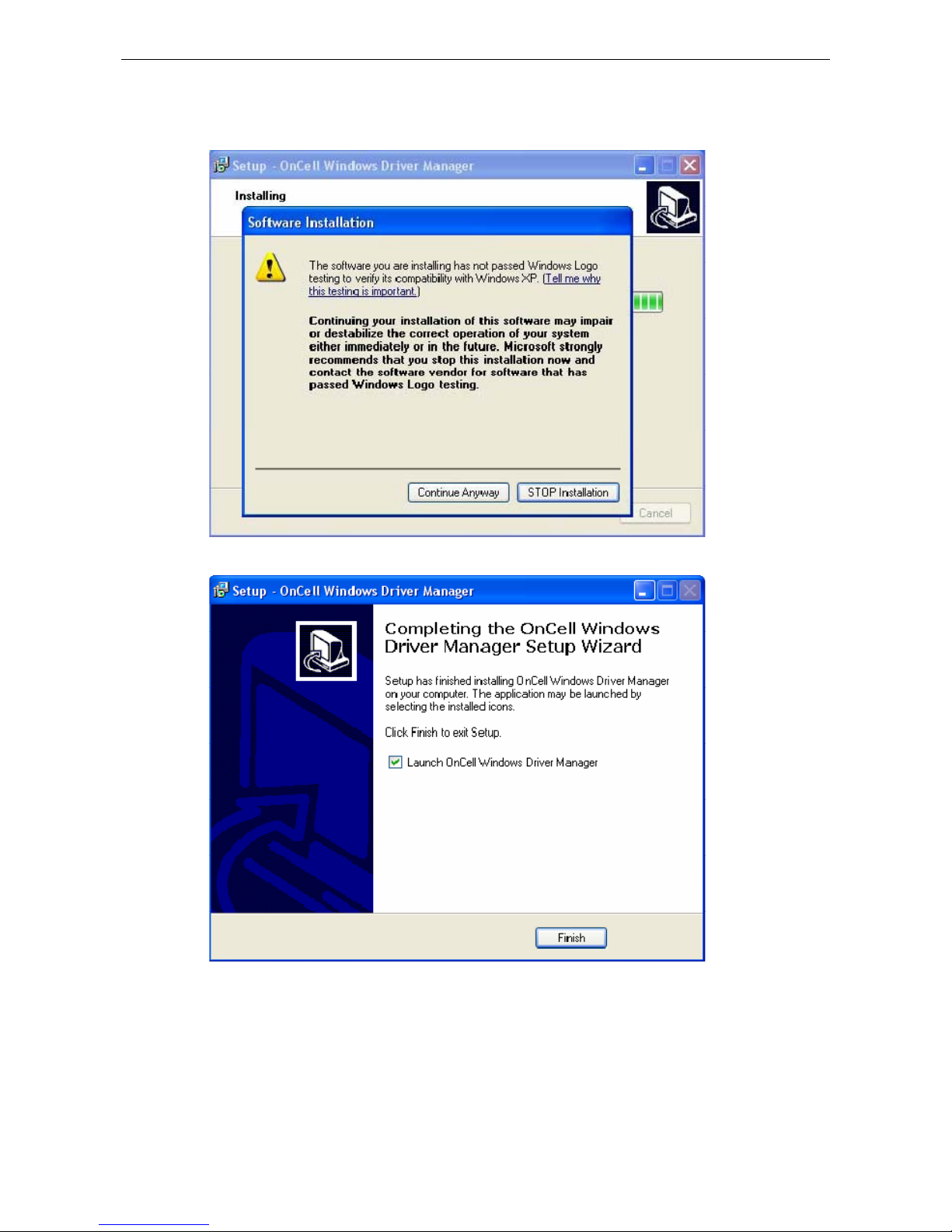
OnCell G3100 Series Configuring Virtual Modem Mode
10-4
5. The setup window will report the progress of the installation. To change the installation settings, click Back
and navigate to the previous screen. On Windows XP, the installer will display a message that the software
has not passed Windows Logo testing, as shown below. Click Continue Anyway to finish the installation.
6. Click Finish to comple te the installation of the OnCell Windows Driver Manager.
Using OnCell Windows Driver Manager
After you install OnCell Windows Driver Manager, you can set up the OnCell G3100’s s erial ports as remote COM
ports for your PC host. Make sure that the serial port(s) on your OnCell G3100 are set to Real COM mode when
mapping COM ports with OnCell Windows Driver Manager.
1. Go to Start Æ OnCell Windows Driver Manager Æ OnCell Windows Driver Manager to start the COM
mapping utility. Click the Add icon.
Page 88
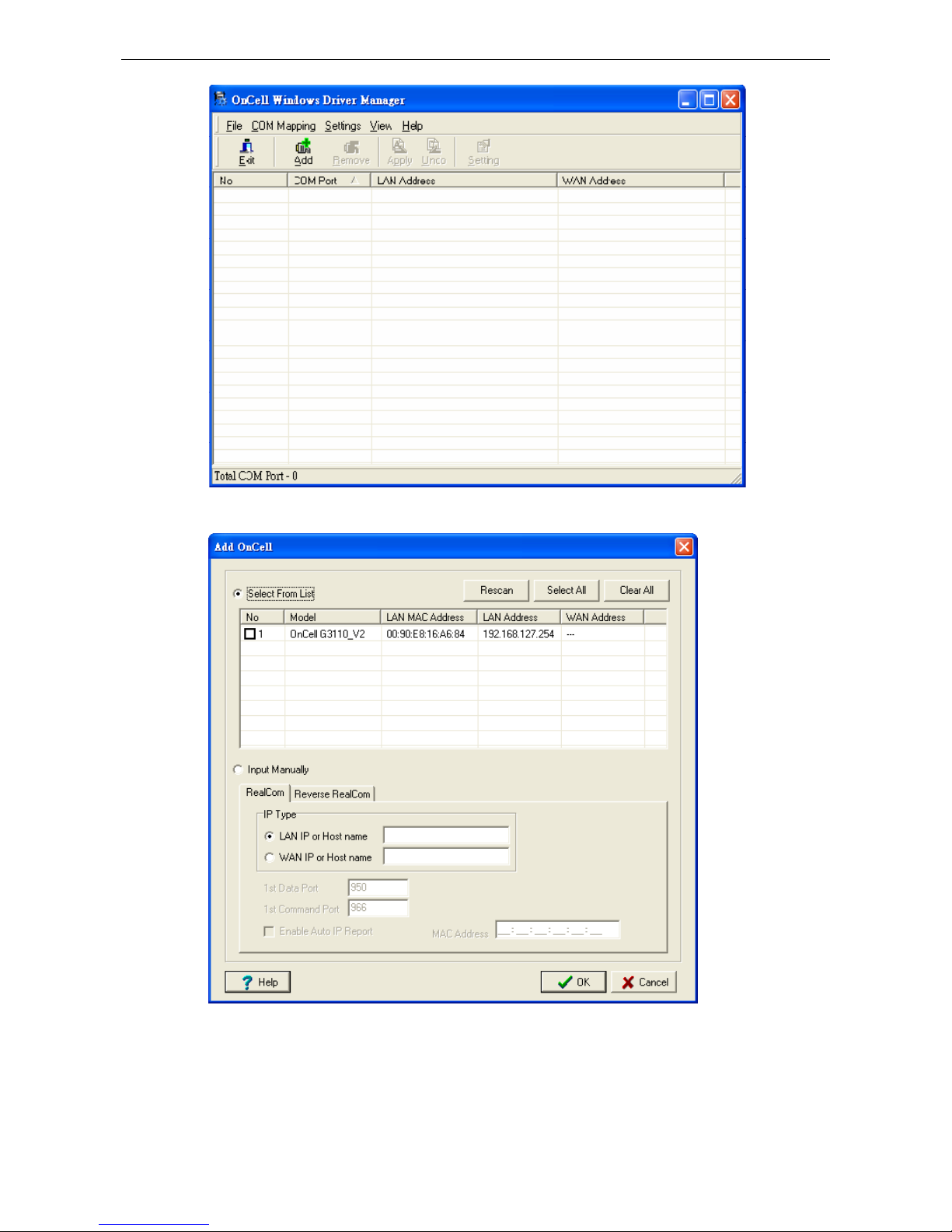
OnCell G3100 Series Configuring Virtual Modem Mode
10-5
2. Click Rescan to search for OnCell IP gateways. From the list that is generated, select the server that you
will map COM ports to, and then click OK.
Page 89
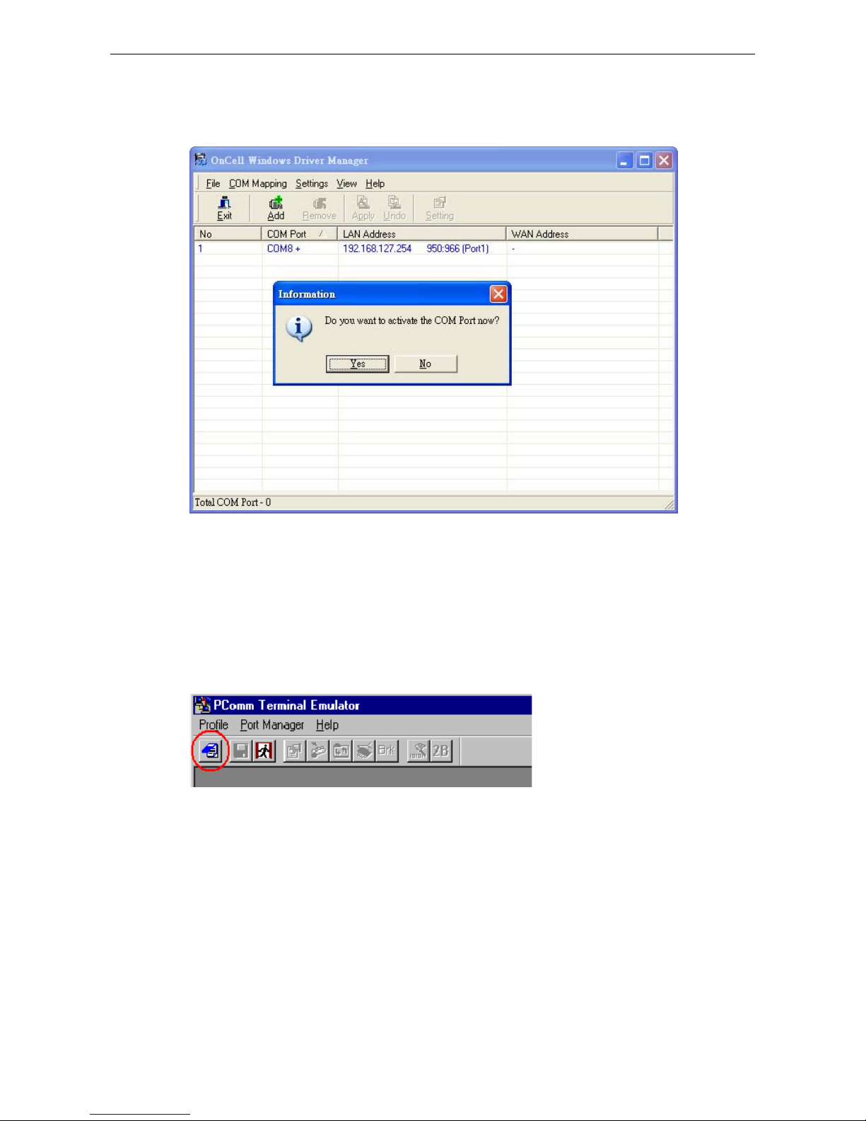
OnCell G3100 Series Configuring Virtual Modem Mode
10-6
3. COM ports and their mappings will appear in blue until they are activated. Activating the COM ports s a ves
the information in the host system registry and makes the COM port available for use. The host computer
will not have the ability to use the COM port until the COM ports are activated. Click Yes to activate the COM
ports at this time, or click No to activate the COM ports later.
Using PComm for Data Transmission
The following instructions and screenshots show how to data transmit using PComm Terminal Emulator, which
is available free of charge as part of the PComm Lite suite. You may use a different terminal emulator utility,
although your actual screens and procedures may vary slightly from the following instructions.
1. From the Windows desktop select Start Æ All Programs Æ PComm Lite Æ Terminal Emulator.
2. The PCo mm Terminal Emulator window should appear. From the Port Manager menu, select Open, or
simply click the Open icon as shown below:
Page 90

OnCell G3100 Series Configuring Virtual Modem Mode
10-7
3. The Prop erty window opens automatically. Select the Communication Parameter tab, and then select
the appropriate COM port for the connection (COM8 in this example). Configure the parameters for 115200,
8, N, 1 (115200 for Baudrate, 8 for Data Bits, None for Parity, and 1 for Stop Bits).
CSD via AT command
Caller dialing out
Use ATD to Dial
+++ is entered to switch to
command mode
Use ATH to Hang Up
Page 91
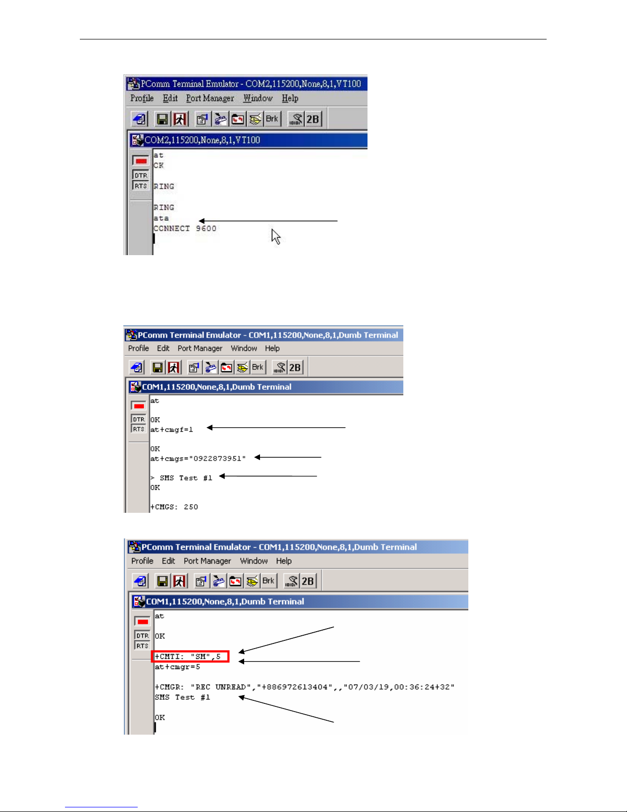
OnCell G3100 Series Configuring Virtual Modem Mode
10-8
Receiver answering a dial-in
SMS via AT command
Illustrating of uUser sending a message
Receiver getting a message
Answer w/ AATTAA
Set 7-bits Ascii
Send my message to“Phone No.”
Enter SMS text and Press
Ctrl+Z here to Send
You’ve Got Mail!
Show Me!
Detailed Message & Info
Page 92

OnCell G3100 Series Configuring Virtual Modem Mode
10-9
GPRS via AT command
You can connect to the Internet (GPRS) via AT com mand. There are two commands you need to know:
APN: AT+CGDCONT=1,”IP”,”<APN>”
Dial: ATD*99***1#
GPRS via Windows Dial-up Network
1. Go to Start Æ Settings Æ Control Panel Æ Phone and Modem Options.
2. Click on Add button.
Page 93

OnCell G3100 Series Configuring Virtual Modem Mode
10-10
3. Check mark the box for Don’t detect my modem; I will select it from a list. Click Next to continue.
4. When the Add Hardware Wizard page appears, select Have Disk.
Page 94

OnCell G3100 Series Configuring Virtual Modem Mode
10-11
5. Browse the CD and select the vmodem_v1.0.2.inf file. Click OK to continue.
6. The OnCell G3100 Modem (GPRS) model has been added to the list. Select it and then click Next.
Page 95

OnCell G3100 Series Configuring Virtual Modem Mode
10-12
7. Click on Selected ports. This COM port needs to be the COM port number mapped by Windows Driver
Manager (not neccessarily COM 1). Choose the COM port created by Windows Driver Manager to proceed,
click Next to continue.
8. A setup windo w will pop up for hardware installation. To change the installation settings, click Back and
navigate to the previous screen. In Windows XP, Setup will display the following message indicating that the
software has not passed Windows Logo testing. Click Continue Anyway to finish the installation.
Page 96
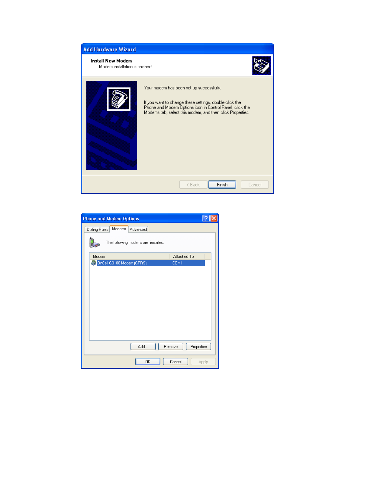
OnCell G3100 Series Configuring Virtual Modem Mode
10-13
9. Click Finish to complete the installation of the new modem.
10. The Phone and Modem Options page will show up. Select and double click on the modem attached to the
COM port (not necessarily COM 1) mapped by Window Driver Manager.
Page 97

OnCell G3100 Series Configuring Virtual Modem Mode
10-14
11. Click on the Advanced tab. Under Extra initialization commands, enter AT+CGDCONT=1, “IP”,
“INTERNET” and click OK to continue.
12. Click OK to close the page. The COM port number will be whichever one was mapped by Windows Driver
Manager.
Page 98
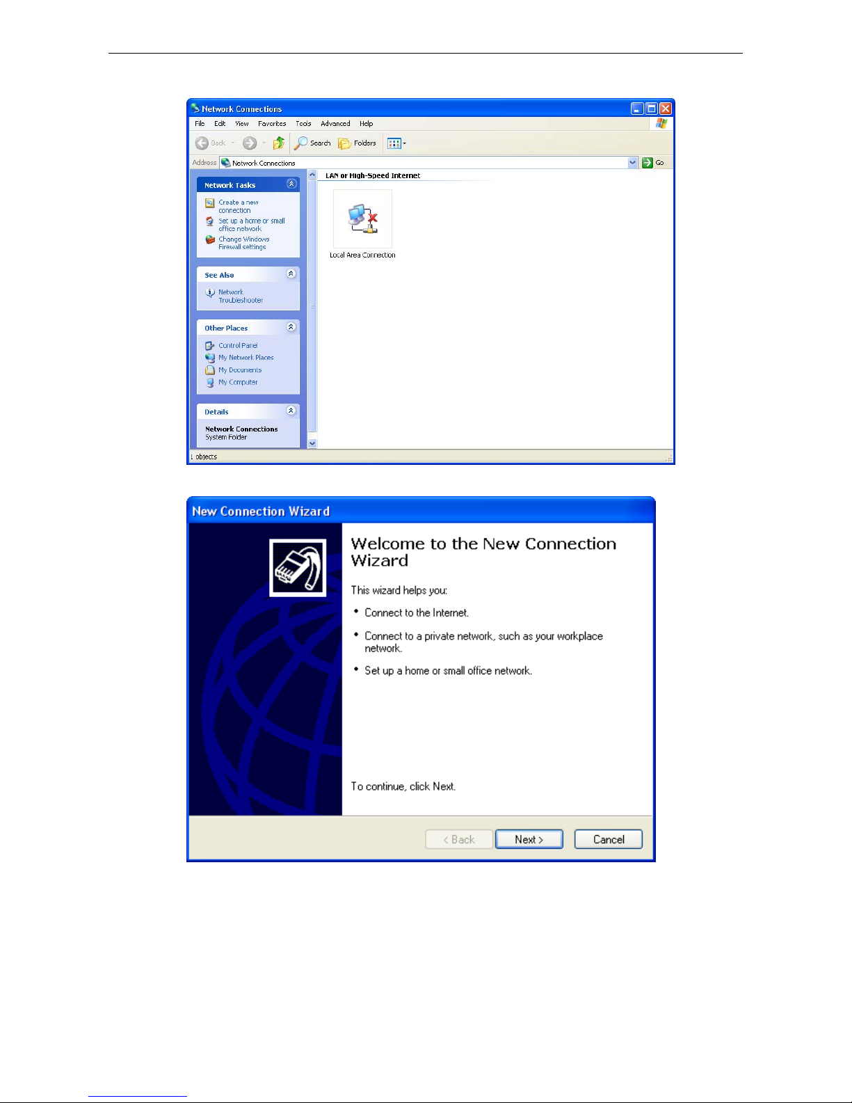
OnCell G3100 Series Configuring Virtual Modem Mode
10-15
13. Go to Start Æ Settings Æ Network Connections Æ Create a new connection.
14. Click on Next.
Page 99
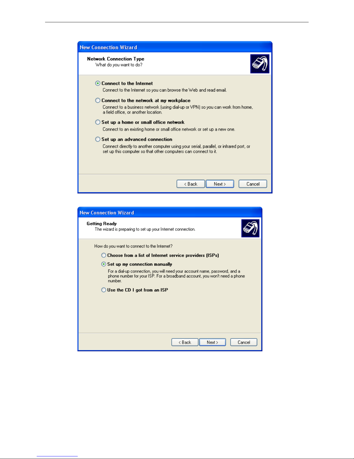
OnCell G3100 Series Configuring Virtual Modem Mode
10-16
15. Select Connect to the Internet, and then click Next.
16. Select Set up my connection manually, and then click Next.
Page 100
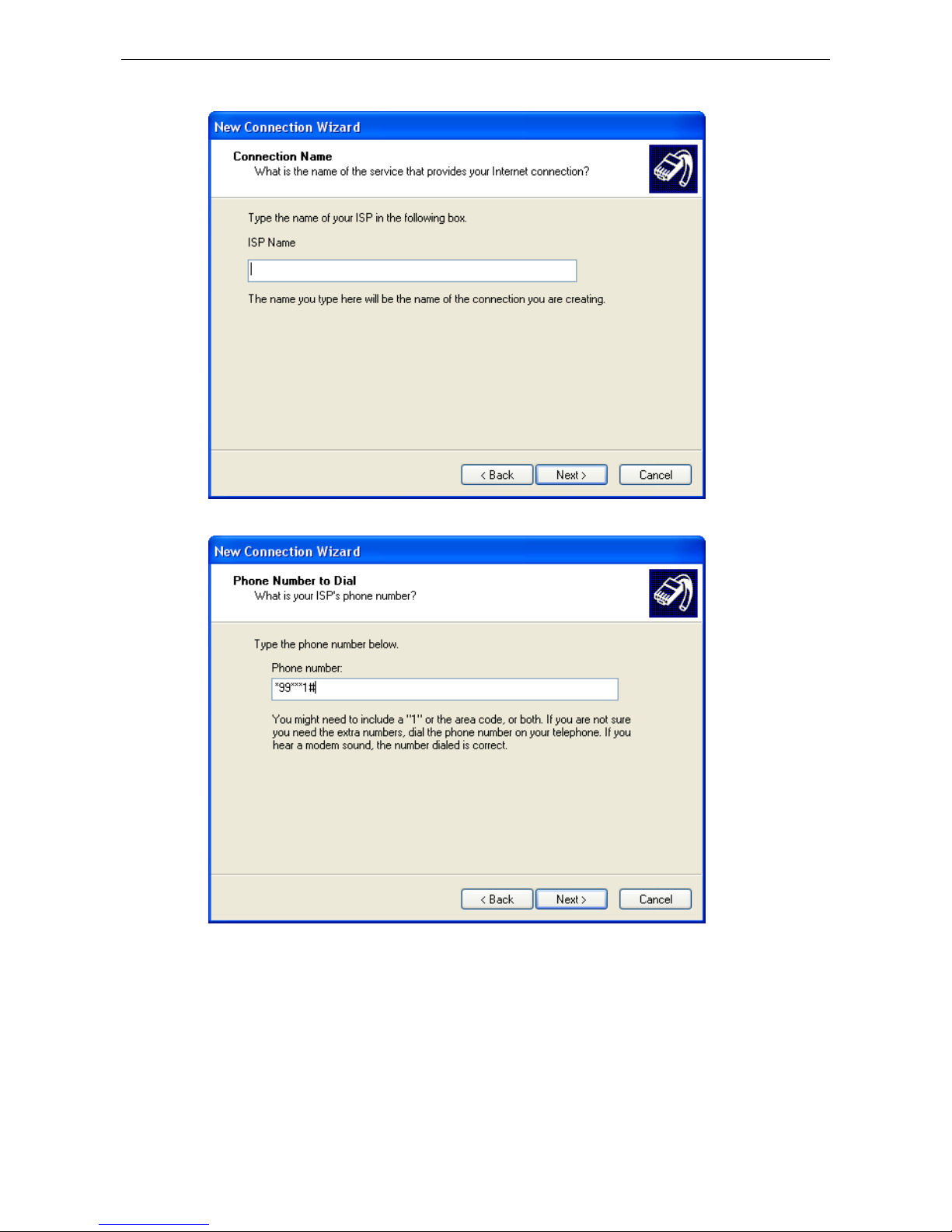
OnCell G3100 Series Configuring Virtual Modem Mode
10-17
17. Create your own ISP name.
18. You must enter *99***1# as a phone number, and click Next.
 Loading...