

Moxa Technologies OnCell G3111, OnCell G3151, OnCell G3211, OnCell G3251 Quick Installation Manual
– 1 – – 2 – – 3 –
P/N: 1802031010011
OnCell G3101/G3201 Series
Quick Installation Guide
Second Edition, Ap ril 2014
Overview
There are curre ntly four mode ls in the OnCe ll G3101/G320 1 series
of IP-modems: the OnCell G3111, OnCell G3151, OnCell G3211,
and OnCell G3251. The main difference between the models is the
serial interface type and number of ports. The OnCell
G3101/G3201 industria l RS-232, RS-232/422/485 GSM/GPRS IP
modems are some of the most affordable, and versatile products
available in the cellular networking market today. These modems
also provide remote access and TCP/IP support, and can be
configured over a network.
Package Checklist
Before Installing the OnCell G3101/G3201 series, verify that the
package contains the following items:
Standard Accessories
• Document & Software CD
• Omni 1 dBi rubber SMA antenna
• (model name: ANT-CQB-ASM -01)
• DIN-Rail Kit
• DC Power Supply (screw-on)
• Rubber stand
• Product warranty statement
• Quick Installat ion Guide
Optional Accessories
• Quad-band GSM/GPRS antennas for OnCell G3101/G3201
series (impedance = 50 ohms):
ANT-CQB-AHSM -00-3m: Omni 0dBi/1 0cm, magnetic
SMA quad-band antenna (impedance = 50 ohms), 3 m
ANT-CQB-AHSM -03-3m: Omni 3dBi/2 5cm, magnetic
SMA quad-band antenna (impedance = 50 ohms), 3 m
ANT-CQB-AHSM -05-3m: Omni 5dBi/3 7cm, magnetic
SMA quad-band antenna (impedance = 50 ohms), 3 m
Note: Please notify your sales representative if any of the above
items are missing or damaged.
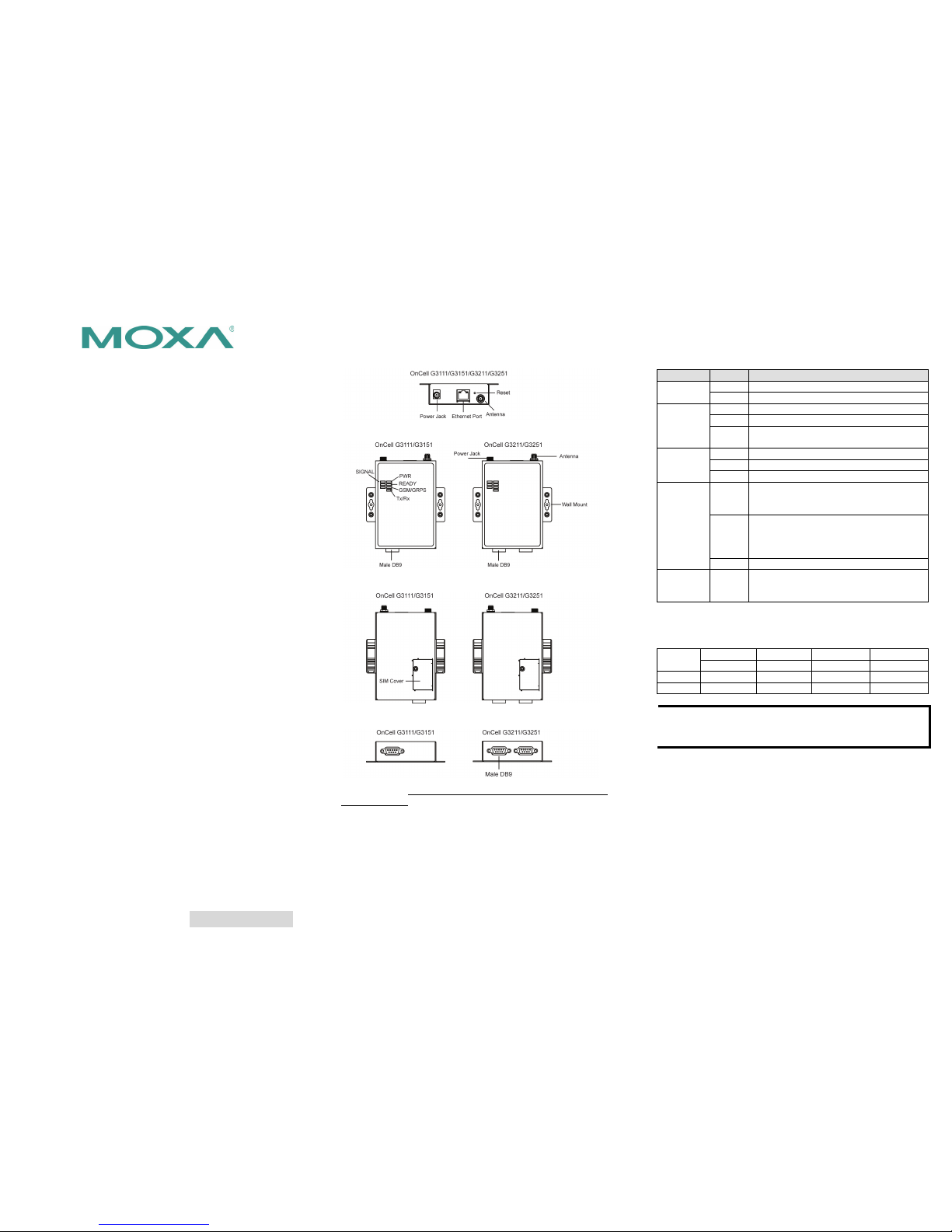
Hardware Introduction
Top View
Front Views
Rear Views
Bottom Views
Reset Button—Press and hold the Reset button for 5 sec to load
factory defaults: Use a pointed object, such as a straightened
paper clip or toothpick, to press the reset button. This will cause
the Ready LED to blink on and off. The factory defaults will be
loaded once the Ready LED stops blinking (after about 5 seconds).
At this point, you should release the reset button (the default IP is
192.168.127.254).
LED Indicators
The LED indicators on the front panel of the OnCell G3101/G3201
are described in the following t able.
Type
Color
LED Function
PWR
Green
Activation of DC Power.
Off
Power is off, or power error condition exists.
TX/RX
Green
The serial port is transmitting data
Amber
The serial port is receiving data .
Off
No data is being transmitted or received
through the serial port.
GSM/GPRS
Green
GSM is connected.
Amber
GPRS is connected.
Off
GSM/GPRS is disconnected.
Ready
Green
Steady on: Software Ready.
Blinking slowly (1 sec):
The OnCell has been
located by the OnCell Search Utility.
Red
(Over
Green)
Steady on: Booting up, or IP fault.
Blinking rapid ly (0.5 sec): IP conflict.
Blinking slowly (1 sec): Cannot get an IP
address from the DHCP server.
Off
Booting up or there is no error condition.
Signal
(3 LEDs)
Green
Number of lit LED s indicates sign al level
(at least 2 LEDs must illuminated for data
transmission)
Adjustable pull high/low resistor for RS-485 Port
DIP switches on the bottom of the OnCell G3151/G3251 are used
to set the pull hig h/low resisto r value for each serial port.
SW
1 2 3 4 Pull High
Pull Low
Terminator
---
ON
1 KΩ
1 KΩ
120 Ω
---
OFF
150 KΩ
150 KΩ
---
---
NOTE
If the pull high/ low resistor on y our device is alr eady set for
RS
-485, make sure the default SW for RS-232 is “OFF”
when you switch back to RS-232 interface.
Hardware Installation Procedure
STEP 1: Open the SIM cover, and insert the SIM card in the SIM
card slot.
STEP 2: Conne ct the 12-48 VDC power adaptor to the OnCell
G3101/G3201 series and then plug the power adaptor into a DC
outlet.
STEP 3: To configure the OnCell, use an Ether net cable to connect
the OnCell directly to your computer’s Ethernet interface.
STEP 4: Conne ct the OnCell G3 101/G3201 serie s’s serial port to a
serial device.
– 4 – – 5 – – 6 –
www.moxa.com/support
The Americas:
+1-714-528-6777 (toll-free: 1-888-669-2872)
Europe:
+49-89-3 70 03 99-0
Asia-Pacific:
+886-2-8919-1230
China:
+86-21-5258-9955 (toll-free: 800-820-5036)
2014 Moxa Inc. All r ights reserved.
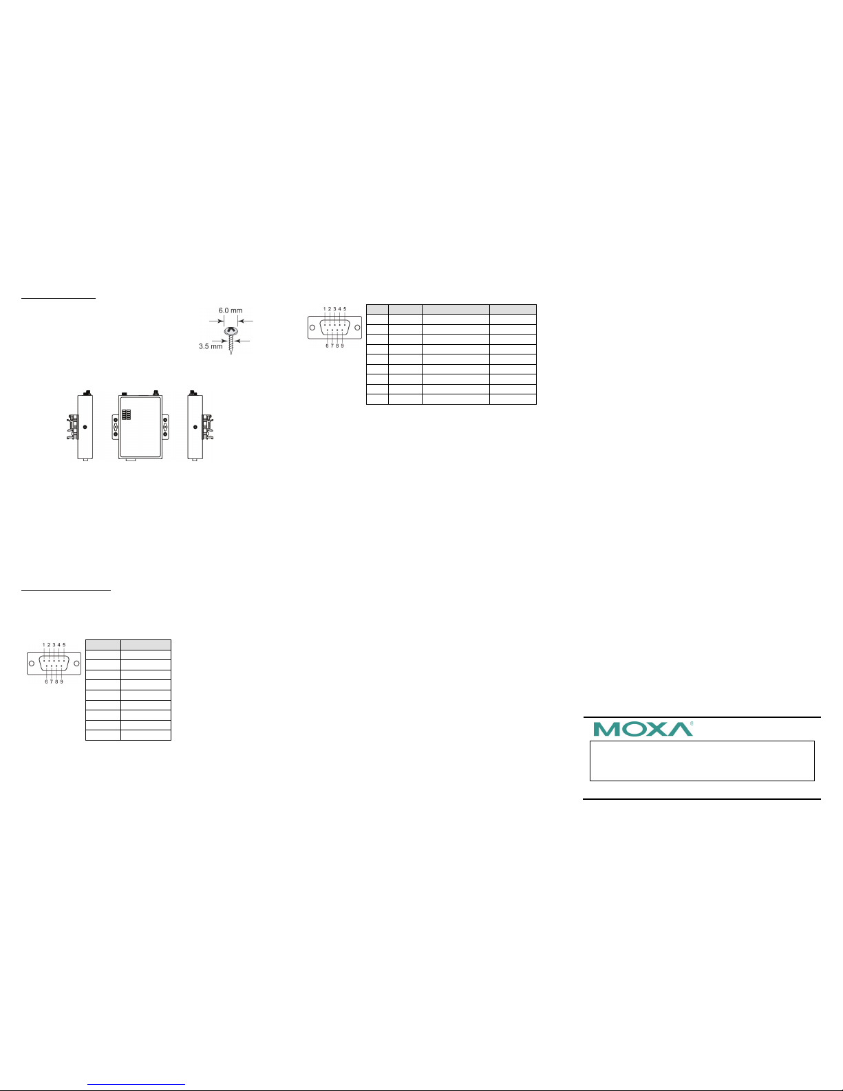
DIN-Rail Mounting
The OnCell G3101 and G3201 series have
built-in “ears” for attaching the IP modem to a
w
all or the insid e of a cabinet. We suggest using
two screws per ear to attach the IP modem to a
wall or the inside of a cabinet. The heads of the
screws should be less than 6.0 mm in diameter,
and the shafts should be less than 3.5 mm in
diameter, as shown in the figure at the right.
Software Installation Information
The Document & Software CD contains the User’s Manual, OnCell
Search Utility, and OnCell Driver Manager. Insert the CD and follow
the on-screen instructions. Please refer to the User’s Manual for
additional deta ils on using the OnCell Search Ut ility and Driver
Manager.
Pin Assignments and Cable Wiring
DB9 Male Port Pinouts
Note that the OnCell G3111 and G3211 only support RS-232. The
RS-422/485 pin as signments only apply to the OnC ell G3151 and
G3251.
DB9 Male
OnCell G3111/G3211 (RS-232)
Pin
RS-232 1 DCD
2
RxD
3
TxD 4 DTR
5
GND
6
DSR 7 RTS
8
CTS
9
---
DB9 Male
OnCell G3151/G3251 (RS-232/422/485)
Pin
RS-232
RS-422/485-4w
RS-485-2w
1
DCD
TxD-(A)
--- 2 RxD
TxD+(B)
--- 3 TxD
RxD+(B)
Data+(B)
4
DTR
RxD-(A)
Data-(A)
5
GND
GND
GND 6 DSR
---
---
7
RTS
---
---
8
CTS
---
--- 9 ---
---
---
Specifications
Cellular In terface
Standards
GSM/GPRS
Band Options
Quad-band 850/900 and 1800/1900 MHz
GPRS Multi-slot Cla ss
Class 10
GPRS Terminal D evice
Class
Class B
GPRS Coding Schemes
CS1 to CS4
Tx Power
1 watt GSM 1800/1900, 2 watts EGSM
850/900
SIM Control
3 V
LAN Interf ace
Number of Ports
1 (For configuration only)
Ethernet
10/100 Mbps, RJ45 connector, Auto
MDI/MDIX
Magnetic Isola tion
Protection
1.5 KV built- in
SIM Interf ace
Number of SIMs
1
SIM Control
3 V
Serial Interface
Number of Ports
1 or 2
Serial Standards
G31
11: 1 RS-232 port
G315
1: 1 RS-232/422/485 port
G3211:
2 RS-232 ports
G3251: 2 RS-232/422/485 ports
ESD Protection
15 KV
Power EFT/
Surge Protection
2 KV
Serial Communication Parameters
Parity
None, Even, Odd, Space, Mark
Data Bits
5, 6, 7, 8
Stop Bit(s)
1, 1.5, 2 (when parity = None)
Flow Control
RTS/CTS, XON/XOFF
Baudrate
50 bps to 921.6 Kbps
Serial Signals
RS-232
TxD, RxD, RTS, CTS, DTR, DSR, DCD, GND
RS-422
Tx+, Tx-, Rx+, Rx-, GND
RS-485-4w
Tx+, Tx-, Rx+, Rx-, GND
RS-485-2w
Data+, Data-, GND
Management Software
OnCell Central
Manager
Centralized management solution for
accessing private IPs from the Internet
(For Software download, Please check on www.moxa.com)
Physical Characteristics
Housing
Aluminum, providing IP30 protection
Dimensions
111 x 77 x 26 mm (4.37 x 3.03 x 1.02 in)
Power Requirements
Number of
Power
Inputs
1 power jack
Input Voltage
12 to 48 VDC
Data Link
335 to 900 mA (peak) @ 12 V
Environmental Limits
Operating
Temperature
-30 to 55°C (-22 to 131°F)
Operating Humid ity
5 to 95% RH
Storage Temperature
-40 to 75°C (-40 to 167°F)
Regulatory Approvals
EMC
CE Class A , FCC Class A, UL
Warranty
Warranty Period
5 years
 Loading...