

Page 1
– 1 – – 2 – – 3 – - 4 -
P/N: 1802050040012
OnCell 5004/5104 Series
Quick Installation Guide
Third Edition, December 2011
Overview
The OnCell 5004/5104 series are high-performance industrial grade
cellular routers that allow up to 4 Ethernet-based devices to
simultaneously use a single cellular data account for primary or
backup network connectivity to remote sites and devices. Both
products provide the functionality of a cellular router, firewall, and
switch in on e single device . The difference between the OnCell 5004
and the 5104 series is that the OnCell 5104 comes with a built-in
relay output that can be configured to indicate the priority of events
to notify and warn engineer s in the field, and the two digital inputs
allow you to connect basic I/O devices, such as sensors, to the
cellular router. In addition, the OnCell 5104 has an IA design and can
be attached to a DIN-rail, whereas the OnCell 5004 can be placed on
a desktop or be wall-mounted. Both products use 12 to 48 VDC
power inputs with a screw-on connector for greater reliability, and
the Ethernet port comes with 1.5 KV magnetic isolation protection to
keep your system safe from unexpected electrical discharges.
Package Checklist
Before Installing the OnCell 5004/5104 series Cellular Router, verify
that the package contains the following items:
Standard Accessories
• Rubber SMA antenna
• Rubber stand (OnCell 5004 series only)
• Wallmount Kit (OnCell 5004 series only)
• Din-Rail Kit (OnCell 5104 series only)
• Terminal block (scre w type)
• Document and Software CD
• Product warranty statement
• Quick Installation Guide
Note: Please notify your sales representative if any of the above
items are missing or damaged.
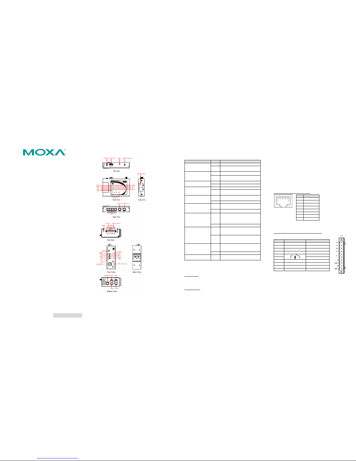
Hardware Introduction
OnCell 5004 series
OnCell 5104 series
Reset Button
Press the Reset Button continuously for 5 sec to load factory default
settings. Use a pointed object, such as a straightened paper clip or
toothpick, to press the reset button. This will cause the Ready LED to
blink on and off. The factory default settings will be loaded once the
Ready LED stops blinking (default LAN IP: 192.168.127.254).
LED Indicators
The following table explains the LED indicators on the front panel of
the OnCell 5004/5104 series:
Type
Color
Meaning
PWR 1
Green
Activation of DC Power
Off
Power is off, or power error
condition exists.
PWR 2
Green
Activation of DC Power
Off
Power is off, or power error
condition exists.
2G
Amber
GPRS/EDGE is connected
Off
GPRS/EDGE is dis connected
3G
Amber
UMTS/HSDPA/HSPA is connected
Off
UMTS/HSDPA/HSPA is
disconnected
SIM 1
Amber
Steady on: SIM 1 is activated
Blinking: SIM 1 n ot inserted
Off
SIM 1 is inactivated
SIM 2
Amber
Steady on: SIM 2 is activated
Blinking: S IM 2 not inserted
Off
SIM 2 is inact ivated
Ready
Green
Steady on: Software Ready.
Blinking s lowly (1 sec): The On Cell
has been located by the OnCell
Search Utility.
off
Power is off, or is booting up.
Fault
Red
Steady on: Booting up, or IP fault.
Blinking s lowly (1 sec): Cannot get
an IP address from the DHCP server
off
Power is off, or there is no error
condition.
LAN 1-4
Green
Steady on: Software Ready.
Blinking s lowly (1 sec): Data
transmissi on
off
Power is off, or is booting up.
Signal (3 LEDs)
Green
Signal Level (at least 2 LEDs must
illuminated for data Transmission)
Connecting the I/O Port
The OnCell 5104/5104 series has six terminals on the terminal block
for the I/O ports, with 4 termina ls used for input, and 2 terminals
used for output.
Digital Inp ut—The power input level de termines the digital inp ut’s
ON/OFF state:
On: +13 to +30 V for state “1”
Off: -30 to +3 V for state “0”
Digital Output—1 relay output with current carrying capacity of 1 A
@ 24 VDC.
Hardware Installation Proce dure
STEP 1: Open the SIM cover, an d insert the SIM card into the SIM
card slot.
STEP 2: Connect the 12-48 VDC power adaptor to the OnCell
5004/5104 series and then plug the power adaptor into a DC outlet.
STEP 3: To configure the OnCell, use an Ethernet cable to connect
the OnCell’s LAN port directly to your computer’s Ethernet interface.
STEP 4: Connect the OnCell 5004/5104 series’ Ethernet port t o an
Ethernet enabled device.
Software Installation Inform ation
The Document & Software CD contains the User’s Manual, and the
OnCell Search Utility. Insert the CD and follow the on-screen
instructions. Please refer t o the User’s Manual for additional details
on using the OnCell Search Utility.
Pin Assignments and Cable Wi ring
Ethernet Port Pin Assignment
Pin
RS-232 1 TxD+ 2 TxD- 3 RxD+ 4 – 5 –
6
RxD- 7 –
8
–
Note: Please read Chapter 2: Getting Started in the OnCell
5004/5104 User’s Manual for more details about installation and
configuration.
Power Input and Relay Outp ut Pinouts
PIN
Name
Function
1
V1+
DC Power input 1
2
V1-
DC Power input 1
3
V2+
DC Power input 2
4
V2-
DC Power input 2
5 Relay Out
6
Relay Out
7
I1
Digital Inp ut
8
COM_1
Digital Inp ut GND
9
I2
Digital Inp ut
10
COM_2
Digital Inp ut GND
Page 2
– 5 – – 6 – – 7 – - 8 -
www.moxa.com/support
The Americas:
+1-714-52 8-6777 (toll-free: 1-888-669-2872)
Europe:
+49 -89-3 70 03 99-0
Asia-Pacific:
+886-2-8919-1230
China:
+86 -21-5258-9955 (toll-free: 800-820-5036)
2010 Moxa Inc. All right s reserved.
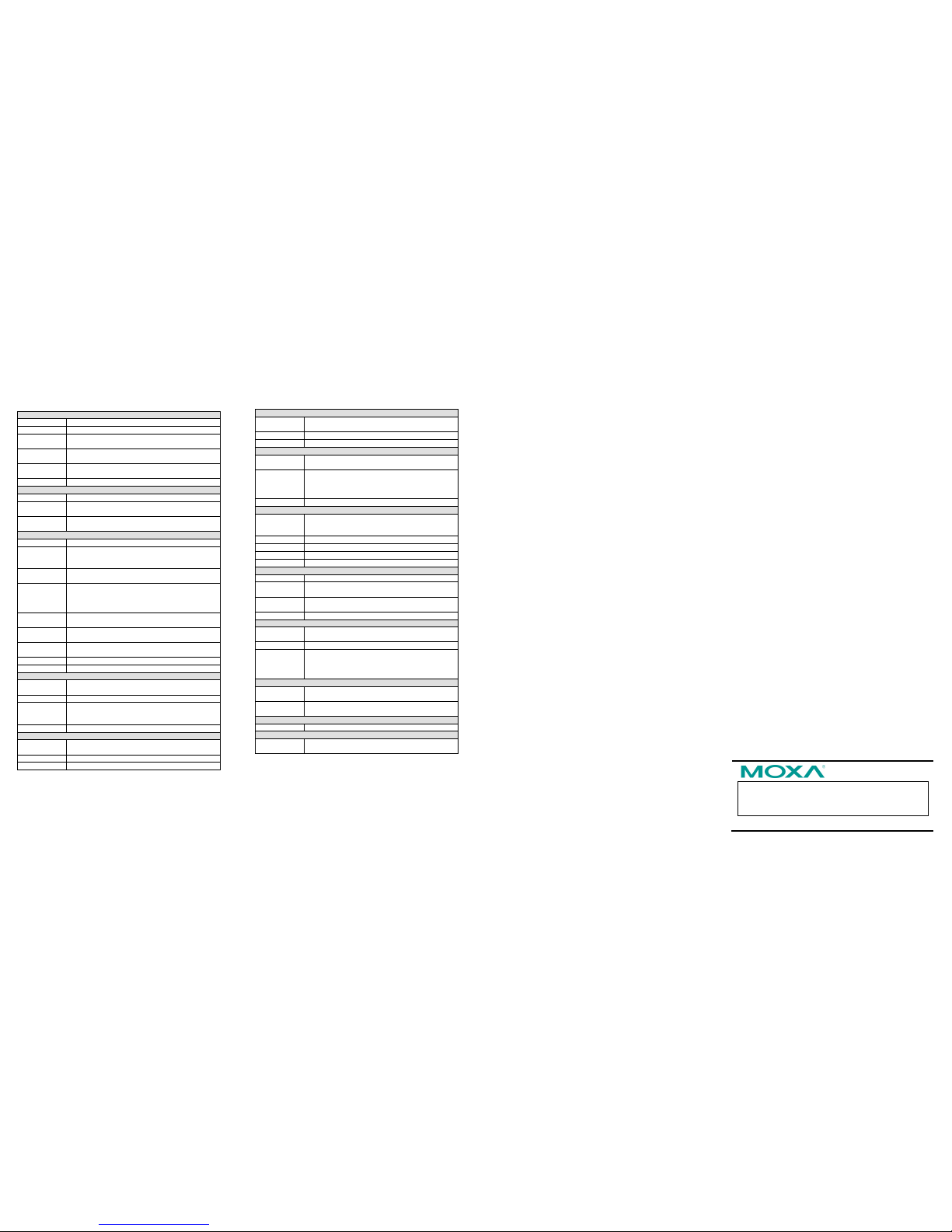
Specifications
Cellular Interface(for OnCell 5004 & OnCell 5104)
Standards
GSM/GPRS
Band Options
Quad-band 850/900 and 1800/1900 MHz
GPRS Multi-slot
Class
Class 10
GPRS Termin al
Device Class
Class B
GPRS Coding
Schemes
CS1 to CS4
Tx Power
1 watt GSM 1800/1900, 2 watts EGSM 850/900
Cellular Interface (for OnCell 5004-HSDPA & 5104-HSDPA)
Standard
GSM/GPRS/EDGE/UMTS /HSDPA
Data Rate
UMTS (DL: 384Kbps, UL: 384Kbps)
HSDPA (DL: 3.6Mbps, UL: 386kbps)
Band Select ion
Tri-band 850/1900/2100 MHz
Quad-band 850/900/1800/1900 MHz
Cellular Interface (for OnCell 5004-HSPA & 5104-HSPA)
Standard
GSM/GPRS/EDGE/UMTS/HSDPA/HSPA+
Data Rate
UMTS (DL: 384Kbps, UL: 384Kbps)
HSDPA (DL: 3.6Mbps, UL: 386kbps)
HSPA+ (DL: 14.4Mbps, UL: 5.76Mbps )
Band Select ion
Five band 800/850/AWS/1900/2100 MHz
Quad-band 850/900/1800/1900 MHz
Tx Power:
1 watt GSM1800
2 watt GSM900
0.25 watt UMTS/HSDPA/HSPA+
0.5 watt EDGE900, 0.4 watt EDGE1800
GPRS Multi-slot
Class:
Class 12
GPRS Termin al
Device Class:
Class B
GPRS Coding
Schemes:
CS1 to CS4
SIM Control:
3V
WAN Interface
Number of
Ports 1 Ethernet
10/100 Mbps, RJ45 connector, Auto MDI/M DIX
Magnetic
Isolation
Protection
1.5 KV built-in
LAN Interface
Number of
Ports
4
Ethernet
10/100 Mbps, RJ45 connector, auto MDI/MDIX
Protection
Built-in 1.5 KV magnetic isolation
SIM Interface
Number of
SIMs
2
SIM Control
3V
I/O Interface (OnCell 5104 series only)
Alarm Contact
1 relay output with current carrying capacity of 1A
@ 24 VDC
Digital Inp uts
The power input level determines the digital input’s
ON/OFF state:
On: +13 to +30 V for state “1”
Off: -30 to +3 V for state “0”
Software
Network
Protocols
UDP, TCP, SNTP, ICMP, DDNS, DHCP/BOOTP,
PPPoE, PPP, DNS Relay, HTTPS, Telnet, RSTP,
IPSec
Router/Firewall
NAT, port forwarding, static routing
Authentication
Local user-name and password
Security
IP filtering
Physical Ch aracteristics
Housing
Aluminum, p roviding IP30 prote ction
Weight
OnCell 5004/5004 series: 505±5 g
OnCell 5104/5104 series: 645±5 g
Dimensions
OnCell 5004/5004 series: 158 x 103 x 34 mm
OnCell 5104/5104 series: 160 x 103 x 50 mm
Power Requirements
Number of
Power Inputs
1 terminal block, 1 power jack
Input Voltage
12 to 48 VDC
Data Link
OnCell 5004 series: 400 mA (idle) to 900 mA
(peak) @ 12 V
OnCell 5104 series: 450 mA (id le) to 950 mA
(peak) @ 12 V
Environmental Limits
Operating
temperature
-30 to 55°C (-22 to 131°F) , 5 to 95% RH
Storage
temperature
-40 to 75°C (-40 to 167°F)
Regulatory Approvals
EMC
CE Class A , FCC Class A, UL
Warranty
Warranty
Period
5 years
 Loading...