

Page 1
– 1 – – 2 – – 3 –
P/N: 1802031500010
NPort Z3150
Quick Installation Guide
First Edition, Novemb er 2011
Overview
NPort Z3150 is a gateway that provides computers with an
Ethernet interface to a ZigBee PAN. Un like a bridge, which logically
extends a PAN across an Internet connection, a gateway provides
network services on behalf of a ZigBee PAN. Software on any
computer can monitor any ZigBee device in the PAN via the NPort
Z3150.
Package Checklist
Before installing the NPort Z3150, verify that the package contains
the following it ems:
Standard Accessor ies
• NPort Z315 0
• Document & Software CD
• RJ45 to RJ45 Ethernet cross-over cable
• Power adaptor (not included with wide temperature models)
• Warranty statement
• Quick Installat ion Guide
• 2.4 GHz omni-directional antenna
Optional Accesso ries
• DK-35A: DIN-rail mounting kit ( 35 mm)
NOTE: Please notify your sales representative if any of the above
items are missing or damaged
Hardware Introduction
LED Indicators
Top Panel LED Indicators
There are three LEDs on NPort Z3150.
LED
Color
Descriptions
Ready/Fau lt Green On: System power on
Blinking: 1) De vice locating 2) Pull
down the reset button
Red
On: System in itialization f ailed
ZigBee Green On: Initialized ZigBe e PAN
successfully
Blinking: ZigBee Tx/Rx
Off: ZigBee PAN initial ization failure
Serial Tx/Rx
Green
Serial data output to serial port
Orange
Serial data input from serial port
End Panel LED I ndicator s
Name
Color
Descriptions
Ethernet
Orange
10 Mbps Ethernet connection
Green
100 Mbps Ethernet connection
Off
Ethernet cable is disconnected or has a short
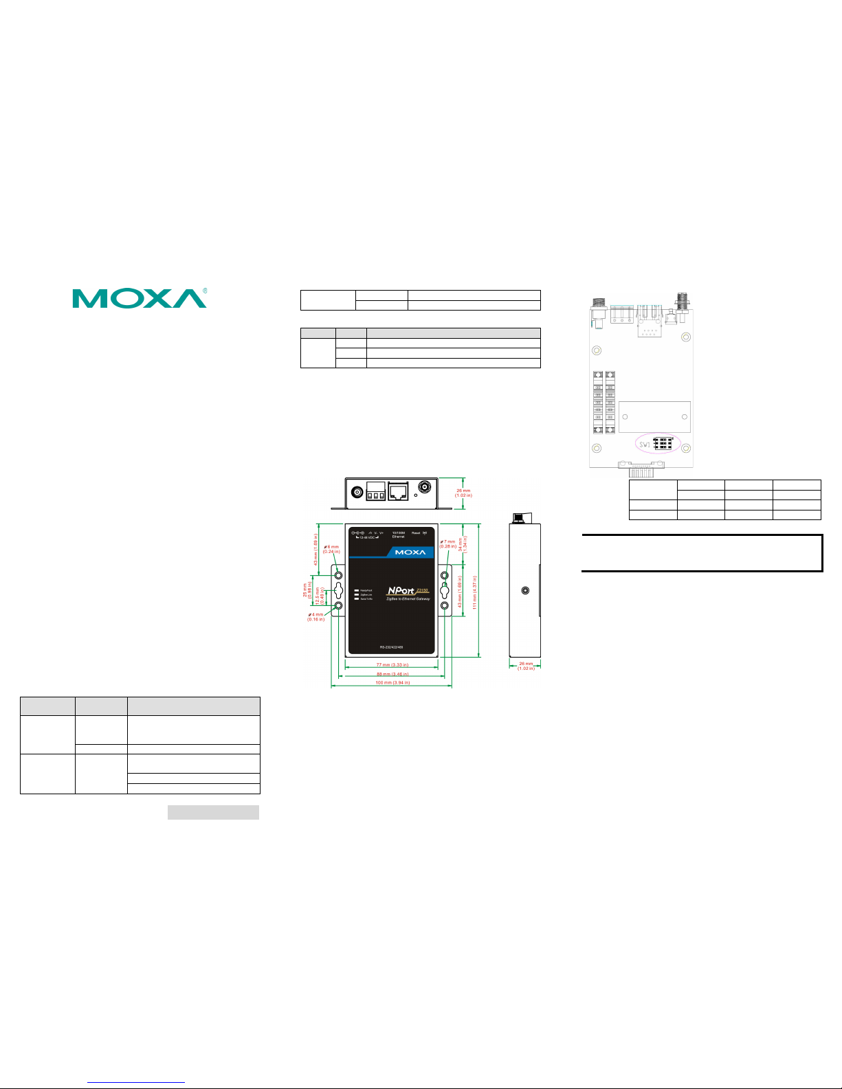
The NPort Z3150 models h ave one serial port. All models support
RS-232/422/485 operation with DB9 connectors, and include one
10/100M Ethernet port.
Reset Button
The reset button is used to load factory defaults. Use a pointed
object such as a straightened paper clip to hold the reset button
down for five seconds. Release the reset button when the Ready
LED stops blinkin g.
Pull High/Low Resistors for RS-422/485
You may need to set the pull high/low resistors when termination
resistors are used for certain RS-422 or RS-485 environments.
SW
1 2 3
Pull High
Pull Low
Terminator
ON
1KΩ
1KΩ
120Ω
Default
OFF
150KΩ
150KΩ
---
NOTE
Do no t us e t he 1KΩ se tt in g whi le in RS-232 mode. Doing so
will degrade the RS
-232 signals and reduce the effective
communication distance.
First-time Hardware Installation
STEP 1: After removing the NPort Z3150 from the box, use a
cross-over Ethernet ca ble to connect the NPort’s RJ45 Ethernet
port directly t o your computer’s.
STEP 2: Attach the power adaptor to the NPort and then plug
the adaptor into an electrical outlet.
STEP 3: Configure the NPort Z3150 through the Ethernet port.
See the next section for software installation information.
Software Installation Information
Insert the Docu mentation & Software CD. A window should open
with several options displayed:
• Click [Documents] and select “NPort Z3150 Series User’s
Manual” to view the user’s manual.
• Click [Install UTILITY] and follow the on-screen instructions
to install the NPort Search Utility. This utility can be used to
search for NPort Z3150 units on the network.
The Factory default IP settings are assigned as follows:
LAN: Static; IP = 192.168.127.254; netmask = 255.255.255.0
Page 2
– 4 – – 5 – – 6 –
www.moxa.com/support
The Americas:
+1-714-528-6777 (toll-free: 1-888-669-2872)
Europe:
+49-89-3 70 03 99-0
Asia-Pacific:
+886-2-8919-1230
China:
+86-21-5258-9955 (toll-free: 800-820-5036)
2011 Moxa Inc. All r ights reserved.
If the NPort is configured for DHCP but the DHCP server cannot be
found, the NPort will use factory default IP settings.
NOTE
If you have forgo tten the NPort’s IP address, use the NPort
Search Utility from your PC to locate the NPort. After
searching the LAN for NPort units, the NPort Search Utility
will display the IP address of ea ch unit.
Open the web console to make configuration changes as follows:
STEP 1: Open your web browser.
STEP 2: In the address bar, enter 192.168.127.254 (the default
IP address).
STEP 3: The web conso le will open, and the cu rrent
configuration settings will be d isplayed.
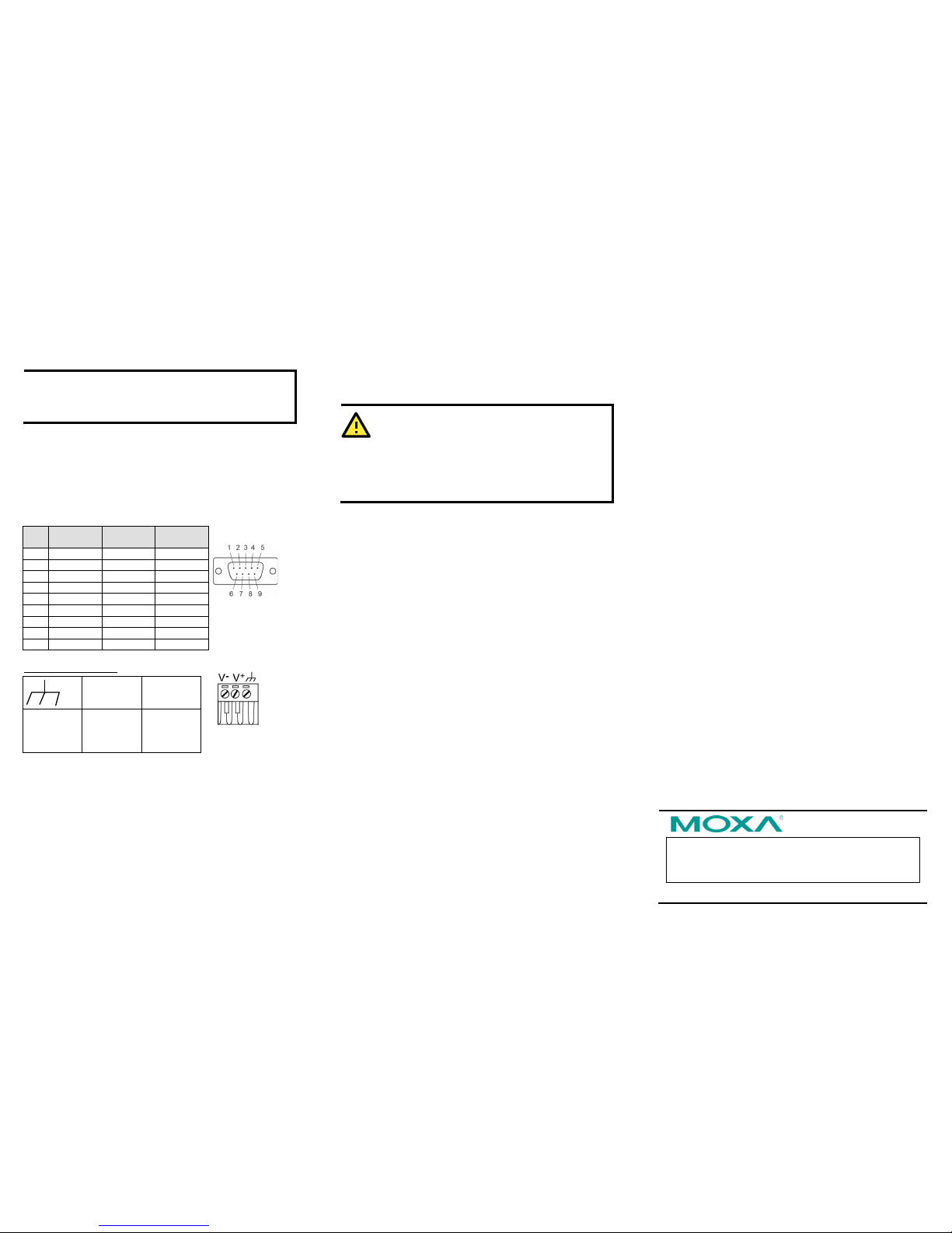
Pin Assignments and Cable Wiring
PIN RS-232 RS-422,
4w RS-485
2w RS-485
1
DCD
TxD-(A)
---
2
RXD
TxD+(B)
---
3
TXD
RxD+(B)
Data+(B)
4
DTR
RxD-(A)
Data-(A)
5
GND
GND
GND
6
DSR
---
---
7
RTS
---
---
8
CTS
---
---
9
---
---
---
Power Input Pinouts
V+
V-
Shielded
Ground
DC Power
Input,
Positive
Electrode
DC Power
Input,
Negative
Electrode
Specifications
Power Requirements
Input Voltage: 12 to 48 VDC
Power Consumption: 120 mA @ 12 V
Connector: Power Jack
Physical Characteristics
Weight: 380g
Dimension:
Without ears: 67 x 100.4 x 22 mm (2.64 x 3.95 x 0.87 in)
With ears: 90 x 100 x 22 mm (3.54 x 3.94 x 0.87 in)
Regulatory Approvals
EMC: CE (EN55022 Class A, EN55024), FCC Part 15 Subpart B
Class A
Safety: UL (UL60950-1), LVD (EN60950-1)
Reliability
Automatic Reb oot Trigger: Built- in WDT (watchdog timer)
WARNING
1. This equipment is intended to be used in a Restricted
Access Location.
2. This product is intended to be s upplied by an UL 609 50-1
and IEC 60950-1 certified power supply marked “LPS” and
rated output rating: 12 to 48 VDC,
120 mA @ 12 V
minimum, 75°C.
 Loading...