

Page 1
– 1 – – 2 – – 3 –
P/N: 1802021504010
NPort Z2150
Quick Installation Guide
First Edition, Novemb er 2011
Overview
The NPort Z2150 is a reliable wireles s serial I/O with su pport for
serial to ZigBee communications. The NPort Z2150 can act as a
ZigBee Coordinator, ZigBee Router or ZigBee End Device. Any
serial device can be connected by the NPort Z2150 and exchange
data via Personal Area Network (PAN).
Package Checklist
Before installing the NPort Z2150, verify that the package contains
the following it ems:
Standard Accessor ies
• NPort Z2150
• Documentation & Software CD
• Power adaptor (not included with wide temperature models)
• Warranty statemen t
• Quick Installat ion Guide
• 2.4 GHz, omni- directional ante nna
Optional Accesso ries
• DK-35A: DIN-rail mounting kit ( 35 mm)
NOTE: Please notify your sales representative if any of the above
items are missing or damaged.
Hardware Introduction
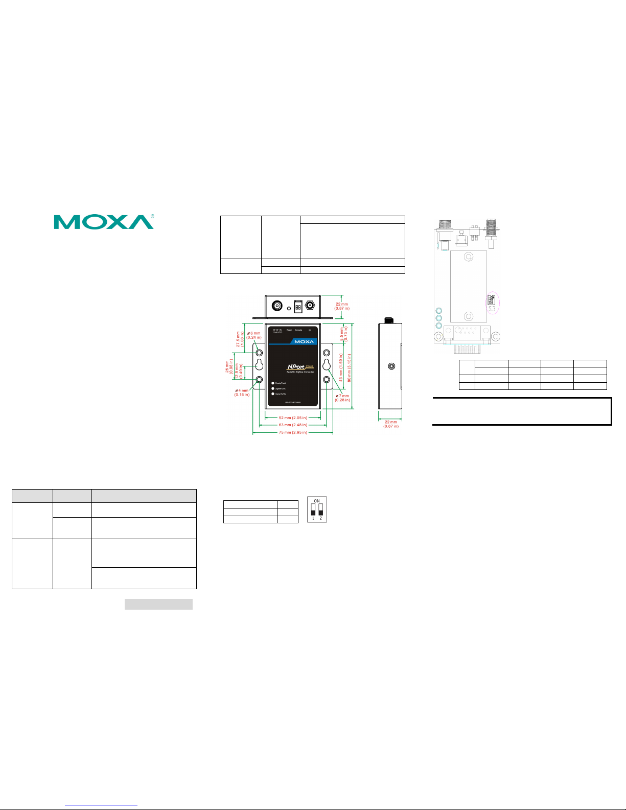
LED Indicators
LED
Color
Descriptions
Ready/Fau lt
Green
On: System power is on
Blinking: Pull down the reset button
Red
Blinking:
1) Node ID conflict
2) Destination node ID disappeared
ZigBee Link
Green
Coordinator:
ON: ZigBee PAN initialized successfully
Blinking: ZigBee Tx/Rx
Off: ZigBee PAN initialization failure
Router:
On: Joined ZigBee PAN successfully
Blinking: ZigBee Tx/Rx
Off: Failure to j oin ZigBee PAN
End Device:
On: Joined ZigBee PAN successfully
Blinking: ZigBee Tx/Rx
Off: Failure to join ZigBee PAN/ parent
node removed
Serial Tx/Rx
Green
Serial data output to serial port
Orange
Serial data input from serial port
The NPort Z2150 models h ave one serial port. All models support
RS-232/422/485 with DB9 connectors.
Reset Button
The reset button is used to load factory defaults. Use a pointed
object such as a straightened paper clip to hold the reset button
down for five seconds. Release the reset button when the Ready
LED stops blinkin g.
DIP Switch
Serial Connect ion
1
Console Mode
ON
Operation Mo de
OFF
Note: 2 re served for future use
Pull High/Low Resistors for RS-422/485
You may need to set the pull high/low resistors when termination
resistors are used for certain RS-422 or RS-485 environments.
SW
1 2 3
4
Pull High
Pull Low
Terminator
Reserved
ON
1KΩ
1KΩ
120KΩ
Default
OFF
150KΩ
150KΩ
NOTE
Do no t us e t he 1KΩ se tt in g whi le in RS-232 mode. Doing so
will degrade the RS
-232 signals and reduce the effective
communication distance.
First-time Hardware Installation
STEP 1: After removing the NPort Z2150 from the box, set
the DIP-switch to console mode and use a cross-over seria l cable
to connect the NPort’s DB9 serial port directly to your computer’s
serial port to c onfigure.
STEP 2: Attach the power adaptor to the NPort and then plug
the adaptor into an electrical outlet.
STEP 3: Configure the NPort Z2150 through the serial port.
See the next section for software installation information.
Software Installation Information
Insert the Docu mentation & Software CD. A window should open
with several options displayed:
• Click Documents and select “NPort Z2150 Series User’s
Manual” to view the user’s manual.
• Click Install Utility and follow the on-screen instructions to
install the ZigBee Configuratio n Utility. This ut ility can be use d
to search for NPort Z2150 units via serial ports.
Page 2
– 4 – – 5 – – 6 –
www.moxa.com/support
The Americas:
+1-714-528-6777 (toll-free: 1-888-669-2872)
Europe:
+49-89-3 70 03 99-0
Asia-Pacific:
+886-2-8919-1230
China:
+86-21-5258-9955 (toll-free: 800-820-5036)
2011 Moxa Inc. All r ights reserved.
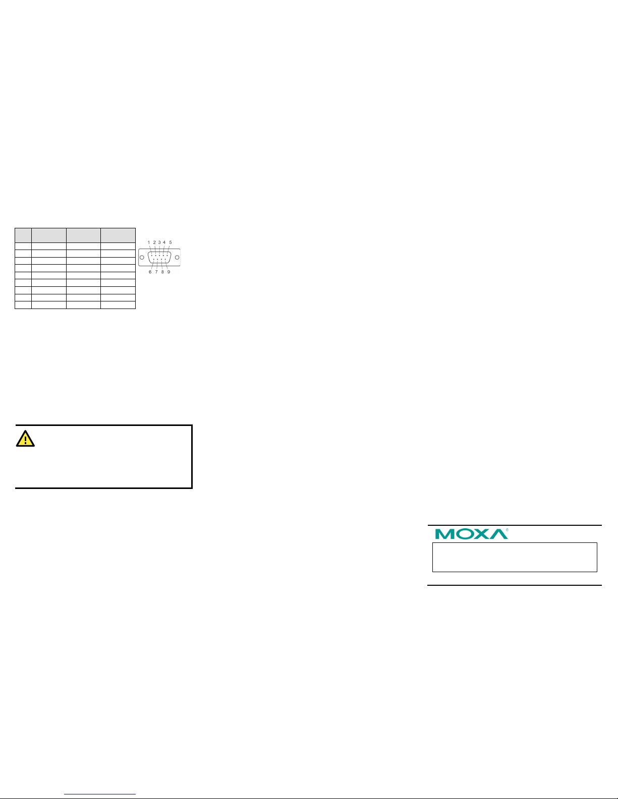
Pin Assignments and Cable Wiring
PIN
RS-232
RS-422,
4w RS-485
2w RS-485
1
DCD
TxD-(A)
---
2
RXD
TxD+(B)
---
3
TXD
RxD+(B)
Data+(B) 4 DTR
RxD-(A)
Data-(A)
5
GND
GND
GND
6
DSR
---
--- 7 RTS
---
---
8
CTS
---
---
9
---
---
---
Specifications
Power Requirements
Input Voltage: 12 to 48 VDC
Power Consumption: 45 mA @ 12 V
Connector: Power Jack
Physical Characteristics
Weight: 340g
Dimension:
Without ears: 52 x 80 x 22 mm (2.05 x 3.15 x 0.87 in)
With ears: 75 x 80 x 22 mm (2.95 x 3.15 x 0.87 in)
Regulatory Approvals
EMC: CE (EN55022 Class A, EN55024), FCC Part 15 Subpart B
Class A
Safety: UL (UL60950-1), LVD (EN60950-1)
WARNING
1. This equipment is intended to be used in a Restricted
Access Location.
2. This product is intended to be s upplied by an UL 609 50-1
and IEC 60950
-1 certified power supply marked “
LPS” and
rated output rating: 12
to 48 VDC, 45 mA @ 12 V
minimum,
75°C.
 Loading...