

Page 1

NPort W2150A/W2250A Series User’s
Manual
Fourth Edition, January 2014
www.moxa.com/product
© 2014 Moxa Inc. All rights reserved.
Page 2

NPort W2150A/W2250A Series User’s
Moxa Americas
Toll
Tel:
Fax:
Moxa China (Shanghai office)
Toll
Tel:
Fax:
Moxa Europe
Tel:
Fax:
Moxa Asia
Tel:
Fax:
Manual
The software described in this manual is furnished under a license agreement and may be used only in accordance with
the terms of that agreement.
Copyright Notice
© 2014 Moxa Inc. All rights reserved.
Trademarks
The MOXA logo is a registered trademark of Moxa Inc.
All other trademarks or registered marks in this manual belong to their respective manufacturers.
Disclaimer
Information in this document is subject to change without notice and does not represent a commitment on the part of
Moxa.
Moxa provides this document as is, without warranty of any kind, e ither expres sed or i mpl ied, incl udin g, but not limit ed
to, its particular purpose. Moxa reserves the right to make improvements and/or changes to this manual, or to the
products and/or the programs described in this manual, at any ti me.
Information provided in this manual is intended to be accurate and reliable. However, Moxa assumes no responsibility for
its use, or for any infringements on the rights of third parties that may result from its use.
This product might include unintentional technical or typographical errors. Changes are periodically made to the
information herein to correct such errors, and these changes are incorporated into new editions of the publication.
Technical Support Contact Information
www.moxa.com/support
-free: 1-888-669-2872
+1-714-528-6777
+1-714-528-6778
+49-89-3 70 03 99-0
+49-89-3 70 03 99-99
-free: 800-820-5036
+86-21-5258-9955
+86-21-5258-5505
-Pacific
+886-2-8919-1230
+886-2-8919-1231
Page 3

Table of Contents
1. Introduction ...................................................................................................................................... 1-1
Overview ........................................................................................................................................... 1-2
Package Checklist ............................................................................................................................... 1-2
Product Features ................................................................................................................................ 1-2
Product Specifications ......................................................................................................................... 1-3
Serial Port Pin Assignments .................................................................................................................. 1-5
2. Getting Started ................................................................................................................................. 2-1
Overview ........................................................................................................................................... 2-2
Panel Layout ...................................................................................................................................... 2-2
LED Indicators .................................................................................................................................... 2-3
Top Panel LED Indicators .............................................................................................................. 2-3
End Panel LED Indicators.............................................................................................................. 2-3
Pull High/Low Resistors for RS-422/485 ................................................................................................. 2-4
Placement Options .............................................................................................................................. 2-5
Connecting the Hardware .................................................................................................................... 2-5
Connecting to the Network ........................................................................................................... 2-6
Connecting the Power .................................................................................................................. 2-6
Connecting to a Serial Device ....................................................................................................... 2-6
3. Initial IP Configuration ..................................................................................................................... 3-1
Overview ........................................................................................................................................... 3-2
Factory Default IP Settings .................................................................................................................. 3-2
Using ARP to Assign IP Address ............................................................................................................ 3-2
Using the Telnet Console to Assign IP Address ........................................................................................ 3-3
Using the Serial Console to Assign IP A ddress ........................................................................................ 3-6
4. Introduction to Operation Modes ...................................................................................................... 4-1
Overview ........................................................................................................................................... 4-2
RealCOM Mode ................................................................................................................................... 4-2
RFC2217 Mode ................................................................................................................................... 4-3
TCP Server Mode ................................................................................................................................ 4-3
TCP Client Mode ................................................................................................................................. 4-3
UDP Mode .......................................................................................................................................... 4-4
Pair Connection Modes ........................................................................................................................ 4-4
Ethernet Modem Mode ......................................................................................................................... 4-4
5. Web Console: Basic Settings ............................................................................................................. 5-1
Overview ........................................................................................................................................... 5-2
Basic Settings .................................................................................................................................... 5-4
6. Web Console: Network Settings ........................................................................................................ 6-1
Overview ........................................................................................................................................... 6-2
Network Settings ................................................................................................................................ 6-2
7. Web Console: Serial Port Settings ..................................................................................................... 7-1
Overview ........................................................................................................................................... 7-2
Web Browser Settings .......................................................................................................... 5-2
Navigating the Web Console .................................................................................................. 5-2
General Settings ......................................................................................................................... 6-2
Ethernet Settings ........................................................................................................................ 6-3
WLAN Settings ............................................................................................................................ 6-4
WLAN ................................................................................................................................. 6-4
Profile................................................................................................................................. 6-6
General Settings for WLAN Profile .......................................................................................... 6-8
Security Settings for WLAN Profile ........................................................................................ 6-12
Security Settings for WEP Encryption .................................................................................... 6-16
Security Settings for WPA, WPA2 ......................................................................................... 6-17
Advanced Settings ..................................................................................................................... 6-20
Serial Port Settings ...................................................................................................................... 7-2
Operation Modes .................................................................................................................. 7-2
Settings for RealCOM Mode ................................................................................................... 7-4
Settings for RFC2217 Mode ................................................................................................... 7-8
Settings for TCP Server Mode .............................................................................................. 7-10
Settings for TCP Client Mode ............................................................................................... 7-14
Settings for UDP Mode ........................................................................................................ 7-18
Settings for Pair Connection Master Mode and Pair Connection Slave Mode................................ 7-20
Settings for Ethernet Modem Mode ....................................................................................... 7-21
Communication Parameters ........................................................................................................ 7-22
Data Buffering/Log .................................................................................................................... 7-24
Page 4

8. Web Console: System Management ................................................................................................... 8-1
Overview ........................................................................................................................................... 8-2
System Management ........................................................................................................................... 8-2
Misc. Network Settings ................................................................................................................. 8-2
Accessible IP List ................................................................................................................. 8-2
SNMP Agent Settings ............................................................................................................ 8-3
User Table .......................................................................................................................... 8-5
Authentication Server ........................................................................................................... 8-6
System Log Settings ............................................................................................................ 8-6
Auto Warning Settings ................................................................................................................. 8-7
Event Settings ..................................................................................................................... 8-7
Serial Event Settings ............................................................................................................ 8-8
E-mail Alert ......................................................................................................................... 8-9
SNMP Trap ........................................................................................................................ 8-10
Maintenance ............................................................................................................................. 8-11
Console Settings ................................................................................................................ 8-11
Maintenance ............................................................................................................................. 8-12
Ping ................................................................................................................................. 8-12
Firmware Upgrade ............................................................................................................. 8-12
Configuration Import .......................................................................................................... 8-13
Configuration Export .......................................................................................................... 8-13
Load Factory Default .......................................................................................................... 8-14
Change Password ............................................................................................................... 8-14
Certificate ................................................................................................................................ 8-15
Ethernet SSL Certificate Import ........................................................................................... 8-15
WLAN SSL Certificate Import ............................................................................................... 8-15
WPA Server Certificate Import ............................................................................................. 8-16
WPA User Certificate Import ................................................................................................ 8-17
WPA User Key Import ......................................................................................................... 8-17
Certificate/Key De l ete ......................................................................................................... 8-18
9. Web Console: System Monitoring ...................................................................................................... 9-1
Overview ........................................................................................................................................... 9-2
System Monitoring .............................................................................................................................. 9-2
Serial Status ............................................................................................................................... 9-2
Serial to Network Connections ............................................................................................... 9-2
Serial Port Status ................................................................................................................. 9-3
Serial Port Error Count ......................................................................................................... 9-3
Serial Port Settings .............................................................................................................. 9-4
System Status ............................................................................................................................ 9-4
Network Connections ............................................................................................................ 9-4
Serial Data Log .................................................................................................................... 9-5
System Log ......................................................................................................................... 9-6
WLAN Status ....................................................................................................................... 9-6
WLAN Site Survey ................................................................................................................ 9-7
10. Web Console: Restart ...................................................................................................................... 10-1
Overview ......................................................................................................................................... 10-2
Restart ............................................................................................................................................ 10-2
Restart System ......................................................................................................................... 10-2
Restart Ports ............................................................................................................................ 10-3
11. Installing and Configuring the Software ......................................................................................... 11-1
Overview ......................................................................................................................................... 11-2
NPort Windows Driver Manager .......................................................................................................... 11-2
Installing NPort Windows Driver Manager ..................................................................................... 11-2
Adding Mapped Serial Ports ........................................................................................................ 11-5
Configuring Mapped Serial Ports .................................................................................................. 11-8
NPort Search Utility ......................................................................................................................... 11-12
Installing NPort Search Utility ................................................................................................... 11-12
Finding NPort Device Servers on Network ................................................................................... 11-14
Modifying NPort IP Addresses.................................................................................................... 11-15
Upgrading NPort Firmware ........................................................................................................ 11-16
Linux Real TTY Driver s .................................................................................................................... 11-17
Basic Steps ............................................................................................................................. 11-17
Installing Linux Real TTY Drive r Files ......................................................................................... 11-17
Mapping TTY Ports ................................................................................................................... 11-18
Removing Mapped TTY Ports ..................................................................................................... 11-18
Removing Linux Driver Files ...................................................................................................... 11-19
UNIX Fixed TTY Driver s ................................................................................................................... 11-19
Installing the UNIX Driver ........................................................................................................ 11-19
Configuring the UNIX Driver ..................................................................................................... 11-20
Page 5

A. SNMP Agents with MIB II & RS-232-Like Groups .............................................................................. A-1
RFC1213 MIB-II Supported SNMP Variables ........................................................................................... A-1
System MIB ................................................................................................................................ A-1
Interfaces MIB ............................................................................................................................ A-1
IP MIB ....................................................................................................................................... A-1
ICMP MIB ................................................................................................................................... A-2
UDP MIB .................................................................................................................................... A-2
Address Translation ..................................................................................................................... A-2
TCP MIB ..................................................................................................................................... A-2
SNMP MIB .................................................................................................................................. A-2
RFC1317: RS-232 MIB Objects ............................................................................................................. A-3
Generic RS-232-like Group ........................................................................................................... A-3
RS-232-like General Port Table ..................................................................................................... A-3
RS-232-like Asynchronous Port Group ............................................................................................ A-3
The Input Signal Table ................................................................................................................. A-3
The Output Signal Table ............................................................................................................... A-3
B. Well Known Port Numbers ................................................................................................................ B-1
C. Ethernet Modem Commands .............................................................................................................. C-1
Dial-in Operation ................................................................................................................................ C-1
Dial-out ............................................................................................................................................. C-1
Disconnection Request from Local Site .................................................................................................. C-1
Disconnection Request from Remote Site ............................................................................................... C-1
AT Commands .................................................................................................................................... C-2
S Registers ........................................................................................................................................ C-3
D. Federal Communication Commission Interference Statement ........................................................... D-1
E. FCC Warning Statement .................................................................................................................... E-1
Page 6

1
1. Introduction
The following topics are covered in this chapter:
Overview
Package Checklist
Product Features
Product Specifications
Serial Port Pin Assignments
Page 7

NPort W2150A/W2250A Series Introduction
1-2
Overview
In this chapter we introduce the basic features and specifications of the NPort W2150A/W2250A and NPort
W2150A/W2250A-T, referred to collectively as the NPort W2150A/W2250A Series.
The NPort W2150A/W2250A Series of wireless device servers are used to co nnect RS-232/422/485 serial
devices such as PLCs, meters, and sensors, to a wired Ethernet LAN or wireless LAN. Your communicat ions
software will be able to access the serial devices from anywhere over a local LAN, WLAN, or the Internet.
Moreover, the WLAN environment offers an excellent solution for applications in which the serial devices are
moved frequently from place to place.
The NPort W2150A/W2250A supports both automatic IP configuration protocols (DHCP, BOOTP) and manual
configuration using a standard web browser. Both IP configuration methods ensure quick and effective
installation. In addition, a utility called “NPort Windows Driver Manager” makes port mapping easy.
The external antenna can be adjusted for maximum signal strength. You can also choose to use your own
antenna for additional flexibility and scalability. A signal strength indicator on the front panel makes it easier for
you to troubleshoot any connection problems.
The NPort W2150A/W2250A Series offers different operation modes to ensure compatibility with standard
network APIs, including TCP Server Mode, TCP Client Mode, and UDP Mode. RealCOM/TTY drivers are provided
to allow legacy serial-based software to communicate over an IP network instantly. This preserves your
software investment while providing all the advantages of networking your serial devices.
For easier management, the NPort W215 0A/W2250A include features such as password authenticatio n , I P
filtering, 64-bit and 128-bit WEP encryption , and SNMP support.
Package Checklist
Standard Accessories
• NPort W2150A, NPort W2150A-T, NPort W2250A, or NPort W2250A-T.
• Document & Software CD
• RJ45 to RJ45 Ethernet cros s -over cable
• Warranty statement
• Quick Installation Guide
Optional Accessories
• DK-35A: DIN-rail mounting kit (35 mm)
• Power jack to terminal block power cable (P/N: 9199000000900)
NOTE: Please notify your sales representative if any of the above items are missing or damaged
Product Features
• Instant connection of any serial device to IEEE 802.11a/b/g network
• RS-232/422/485 ports supporting baudrates up to 921.6 Kbps
• Web-based configuration over Ethernet or WLAN
• Enhanced remote configuration with HTTPS, SSH
• Secure data access with WEP, WPA, WPA2
• Built-in WLAN site survey Tool
• Fast roaming when signal strength is weak
• Per-port offline port buffering and serial data log
• Dual power inputs via power jack and terminal block
Page 8

NPort W2150A/W2250A Series Introduction
1-3
Ethernet Interface
Number of Ports:
Speed:
Connector:
Magnetic Isolation Protection:
WLAN Interface
Standard Compliance:
Network Modes:
Transmit Power:
802.11a: 14 dBm (typical)
802.11b: 17 dBm
802.11g: 15 dBm (typical)
Receive Sensitivity:
Radio Frequency Type:
Transmission Rate:
802.11a: 54 Mbps
802.11b: 11 Mbps
802.11g: 54 Mbps (max.) with auto fallback (54, 48, 36, 24, 18, 12, 11, 9, 6, 5.5, 2, 1 Mbps)
Transmission Distance:
Up to 100 meters (in open areas)
Wireless Security:
• WEP: 64
• WPA, WPA2, 802.11i: Enterprise mode and Pre
• Encryption: 128
EAP
GTC,
EAP
Antenna Connector:
Serial Interface
Number of Ports:
NPort W2150A: 1
NPort W2250A: 2
Serial Standards:
Off
NPort W2150A: 20 MB
NPort W2250A: 10 MB
Serial Line Surge Protection:
Serial Communication Parameters
Data Bits:
Stop Bits:
Parity:
Flow Control:
Baudrate:
Serial Data Log:
Serial Signals
RS
RS
RS
RS
Product Specifications
1
10/100 Mbps, auto MDI/MDIX
RJ45
1.5 KV built-in
802.11a/b/g
Infrastructure, Ad-Hoc
(typical)
-80 dBm
DSSS/OFDM
-bit/128-bit data encryption
-Share Key (PSK) mode
-bit TKIP/AES-CCMP EAP-TLS, PEAP/GTC, PEAP/MD5, PEAP/MSCHAPV2, EAP-TTLS/PAP,
-TTLS/CHAP, EAP-TTLS/MSCHAP, EAP-TTLS/MSCHAPV2, EAP-TTLS/EAP-MSCHAPV2, EAP-TTLS/EAP-
-TTLS/EAP-MD5, LEAP
Reverse SMA
RS-232/422/485 (DB9 male connector)
-line Port Buffering:
1 KV (level 2)
5, 6, 7, 8
1, 1.5, 2
None, Even, Odd, Space, Mark
RTS/CTS, XON/XOFF
50 bps to 921.6 Kbps
64 KB
-232: TxD, RxD, RTS, CTS, DTR, DSR, DC D, GN D
-422: TxD+, TxD-, RxD+, RxD-, GND
-485-4w: TxD+, TxD-, RxD+, RxD-, GND
-485-2w: Data+, Data-, GND
Page 9

NPort W2150A/W2250A Series Introduction
1-4
Software
Network Protocols:
HTTPS
Configuration Options:
Secure Configuration Options:
Fixed TTY Drivers:
Solaris 10, FreeBSD, AIX 5.x, HP
Linux Real
Utilities:
Management:
Windows Real COM Drivers:
2012 x64, Embedded CE 5.0/6.0, XP Embedde
Physical Characteristics
Housing:
Weight:
Product only
Packaged
Dimensions:
Without ears or antenna: 77 x 111 x 26 mm (3.03 x 4.37 x
With ears, without antenna: 100 x 111 x 26 mm (3.94 x 4.37 x 1.02 in)
Antenna Length: 109.79 mm (4.32 in)
Environmental Limits
Operating Temperature:
Standard Models: 0 to 55°C (32 to 131°F)
Wide Temp. Models:
Storage Temperature:
Ambient Relative Humid it y:
Power Requirements
Input Voltage:
Power Consumption:
NPort W2150A: 237 mA @ 12 VDC
NPort W2250A: 237 mA @ 12 VDC
Standards and Certifications
Safety:
EMC:
EMI:
EMS:
EN61000
Radio:
Power Line Surge Protection:
Reliability
Alert Tool:
Automatic Reboot Trigger:
Warranty
Warranty Period:
Details:
ICMP, IP, TCP, UDP, DHCP, Telnet, DNS, SNMP V1/V2c /V 3, HTTP, SMTP, SNTP, SSH,
Web Console, Serial Console, Telnet Console, Windows Utility
HTTPS, SSH
SCO Unix, SCO OpenServer, UnixWare 7, UnixWare 2.1 , S VR 4.2, QNX 4.25, QNX 6,
-UX 11i
TTY Drivers: 2.4.x, 2.6.x, 3.x
NPort Search Utility and NPort Windows Driver manager
SNMP MIB-II
Windows 95/98/ME/NT/2000, Windows XP/2003/Vista/2008/7/8 x86/x64,
d
Aluminum sheet metal (1 mm)
NPort W2150A: 173 g
NPort W2250A: 177 g
NPort W2150A: 547 g
NPort W2250A: 557 g
1.02 in)
-40 to 75°C (-40 to 167°F)
-40 to 85°C (-4 to 185°F)
5 to 95% (non-condensing)
12 to 48 VDC
UL 60950-1, EN 60950-1
CE, FCC
FCC Part 15 Subpart B Class A, FCC Subpart C/E, VCCI, EN 55022 Class A
EN 55024, EN61000-4-2 (ESD), EN61000-4-3 (RS), EN61000-4-4 (EFT), EN61000-4-5 (Surge),
-4-6 (CS), EN61000-4-8, EN61000-4-11
CE (ETSI EN 301 893, ETSI EN 300 328), ARIB RCR STD-33, ARIB STD-66
2 KV (level 3)
RTC (real-time clock)
Built-in WDT (watchdog timer)
5 years
See www.moxa.com/warranty
Page 10

NPort W2150A/W2250A Series Introduction
1-5
Serial Port Pin Assignments
Pin RS-232 RS-422/ RS-485 (4W) RS-485 (2W)
1 DCD TxD-(A) --2 RXD TxD+(B) --3 TXD RxD+(B) Data+(B)
4 DTR RxD-(A) Data-(A)
5 GND GND GND
6 DSR --- --7 RTS --- --8 CTS --- --9 --- --- ---
Page 11

2
2. Getting Started
The following topics are covered in this chapter:
Overview
Panel Layout
LED Indicators
Top Panel LED Indicators
End Panel LED Indicators
Pull High/Low Resistors for RS-422/485
Placement Options
Connecting the Hardware
Connect ing to the Network
Connect ing the Power
Conne cting to a Serial Device
Page 12
NPort W2150A/W2250A Series Getting Started
2-2
Overview
This chapter presents the hardware features of the NPort W2150/W2250A Series and explains how to connect
the hardware.
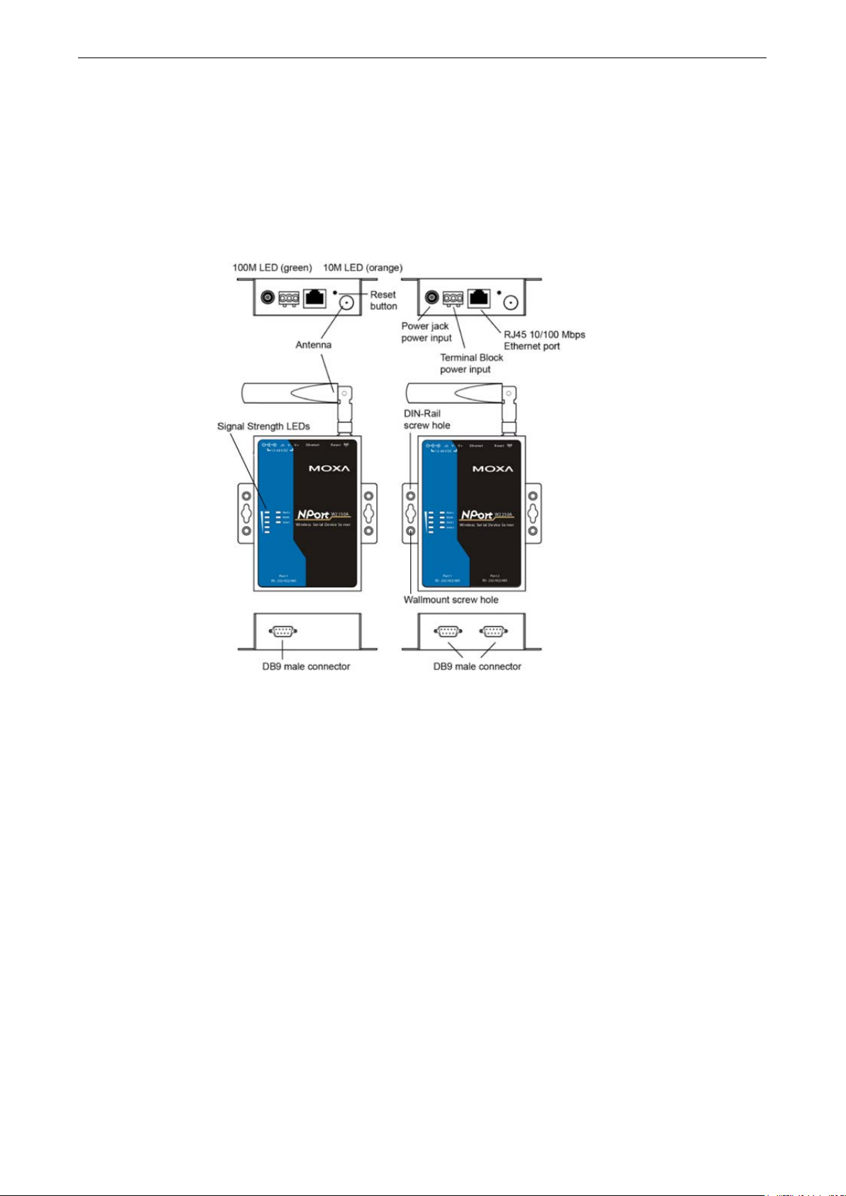
Panel Layout
NPort W2150A/W2150A-T NPort W2250A/W2250A-T
Page 13

NPort W2150A/W2250A Series Getting Started
2-3
LED Indicators
Top Panel LED Indicators
Name Color Function
Steady on: Power is on and NPort is booting up.
Blinking: IP conflict or DHCP/ BOOTP s erver did not respond properly.
Steady on: NPort is functioning normally.
Blinking: Unit is responding to Locate function.
Steady on: Wireless enabled
Blinking: NPort can’t establish WLAN connection with AP
(Infrastructure) or station (Ad-Hoc)
1 Red - the signal strength is between 0% and 20%
2 Red - the signal strength is between 21% and 40%
3 Green - the signal strength is between 41% and 6 0%
4 Green - the signal strength is between 61% and 80%
5 Green - the signal strength is between 81% and 100%
Ready
WLAN
Serial 1
Serial 2
Signal Strength
(5 LEDS)
Red
Green
Off Power is off or a power error condition exists.
Green
Off Wireless not enabled.
Orange Serial port is receiving data.
Green Serial port is transmitting data.
Off No data is flowing to or from the serial port.
Red
Green
End Panel LED Indicators
Name Color Function
Orange
Ethernet
Green
Off Ethernet cable is disconnecte d
10 Mbps Ethernet connection
100 Mbps Ethernet connection
Page 14
NPort W2150A/W2250A Series Getting Started
2-4
ATTENTION
Do not use the 1 KΩ
232 signals and reduce the
effective communication distance.
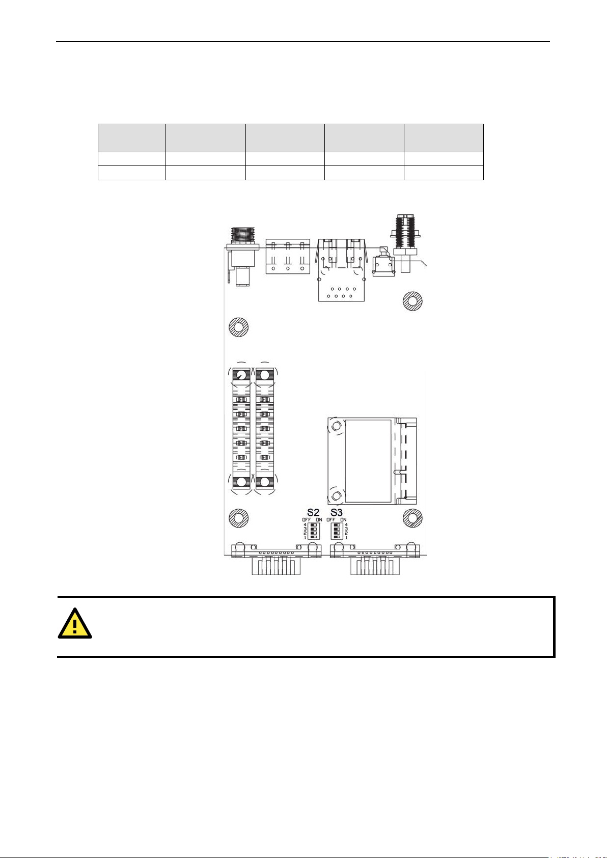
Pull High/Low Resistors for RS-422/485
You may need to set the pull high/low r esistors when termination resistors are used for certain RS-422 or
RS-485 environments.
S2 (Serial 1)
S3 (Serial 2)
ON 1 KΩ 1 KΩ 120 Ω -----
OFF *150 KΩ *150 KΩ *N/A -----
*Default
S3 is for NPort W2250A only
DIP 1
Pull high resistor
DIP 2
Pull low resistor
DIP 3
Terminal resistor
DIP 4
Reserved
setting while in RS-232 mode. Doing so wil l d eg rade the RS-
Page 15
NPort W2150A/W2250A Series Getting Started
2-5
ATTENTION
Before connecting the hardware, follow these important wiring safety precautions:
Disconnect power source
Do not install or wire this unit or any attached devices with the power connected. Disconnect the power before
installation by removing the power cord before installing and/or wiring your unit.
Follow maximum current ratings
Calculate the maximum possible current in each power wire and c
dictating the maximum current allowable for each wire size.
If the current goes above the maximum ratings, the wiring could overheat, causing serious damage to your
equipment.
Use caution
The unit will generate heat during operation, and the casing may feel hot to the touch. Take care when handling
unit. Be sure to leave adequate space f or ventilation.
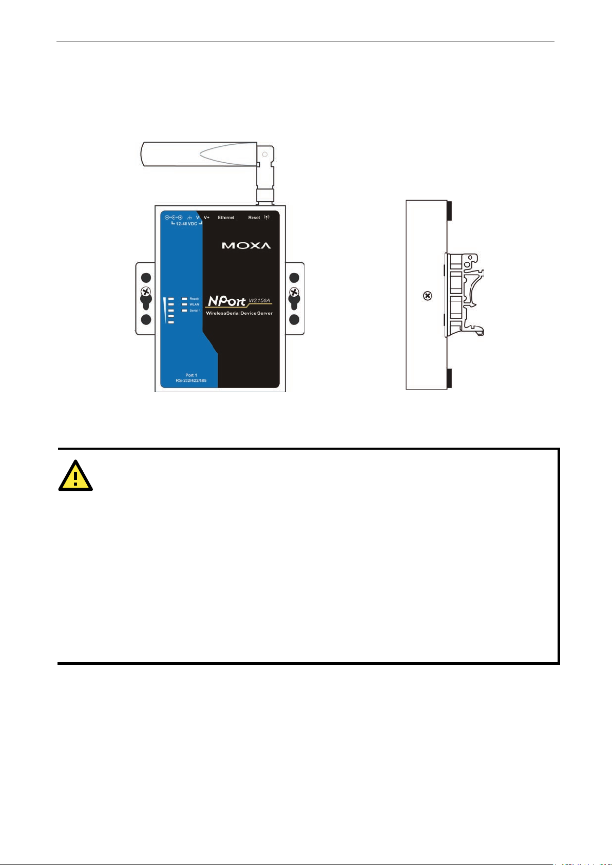
Placement Options
The NPort can be placed on a desktop or other horizontal surfac e. You c an al s o i nstall t he N Por t on a DIN-rail
or on the wall.
Wall Mounting DIN-Rail Mounting
Connecting the Hardware
ommon wire. Observe all electrical codes
- unit may get hot
The following guide lines will help ensure trouble-free signal commun ica tio n with th e NPort .
• Use separate paths to route wiring for power and devices to avoid interference. Do not run signal or
communication wiring and power wiring in the same wire conduit. The rule of thumb is that wiring that
shares similar electrical characteristics can be bundled together .
• If power wiring and device wiring paths must cross, make sure the wires are perpendicular at the
intersection point.
• Keep input wiring and output wiring separate.
• Label all wiring to each device in the system for easier testing and troubleshooting
Page 16

NPort W2150A/W2250A Series Getting Started
2-6
Connecting to the Network
Use the supplied Ethernet cable to connect the NPort to your Ethernet network. If the cable is properl y
connected, the NPort will indica te a v alid connection to the Ethernet as follows:
• A green Ethernet LED indicates a vali d connection to a 100 Mbps Ethernet network.
• An orange Ethernet LED indicates a valid connection to a 10 Mbps Ethernet network.
• A flashing Ethernet LED indicates that Ethernet packets are being transmitted or received.
Connecting the Power
Connect the VDC power line (12 to 48 V) to the NPort’s power jack or terminal block. If power is properly
connected, the “Ready” LED will initially glow red. When the system is ready, the “Ready” LED will turn green.
Connecting to a Serial Device
Use a serial cable to connect your serial device to a serial port on the NPort.
Page 17

3
3. Initial IP Configuration
The following topics are covered in this chapter:
Overview
Factory Default IP Settings
Using ARP to Assign IP Address
Using the Telnet Console to Assign IP Address
Using the Serial Console to Assign IP Address
Page 18

NPort W2150A/W2250A Series Initial IP Configuration
3-2
ATTENTION
The LAN and WLAN interfaces cannot be used at the same time. If the Ethernet link is active, then WLAN
connections will be disabled. I f the WLAN connec
ATTENTION
Make sure that the Ethernet cable is connected before powering up the NPort.
ATTENTION
If you forget the IP address of your NPort, you can l ook it up using the NPort Searc h Utility. After NPort Search
Utility has found all NPorts on the network, each unit will be listed with its IP address. Please refer to Chapter
11 for additional information on using NPort Search Utility.
Overview
This chapter presents several ways to assign the NPort’s IP address for the first time. Please refer to Chapter
2 for instructions on connecting to the network.
The web console is the recommended method for configuring the NPort. Please refer to Chapter 5 and 6 for
details on using the web console fo r configuration.
tion is active, then the Ethernet link will be disabled.
Factory Default IP Settings
Network Interface IP Configuration IP Address Netmask
LAN Static 192.168.126.254 255.255.255.0
WLAN Static 192.168.127.254 255.255.255.0
If your NPort is configured to obtain its IP settings from a DHCP or BOOT P server but is unable to get a response,
it will use the factory default IP address and netmask.
Using ARP to Assign IP Address
The ARP (Address Resolution Protocol) command can be used to assign an IP address to the NPort. The ARP
command tells your computer to associate the NPort’s MAC address with the specified IP address. You must
then use Telnet to access the NPort, at which point the device server’s IP address will be reconfigured. This
method only works when the NPort is configured with default IP settings.
1. Select a valid IP address for your NPort. Consult with your network administrator if necessary.
2. Obtain the NPort’s MAC address from the label on its bottom panel.
3. From the DOS pro mpt , exe cu te the arp -s command with the desired IP addr ess and the NPort’s MAC
address, as in the following example:
arp -s 192.168.200.100 00-90-E8-xx-xx-xx
In this example 192.168.200.100 is the new IP addr ess that will be assigned to the NPor t, a nd
00-90-E8-xx-xx-xx is the NPort’s MAC address.
4. From the DOS prompt, execute a special T elnet command using port 6000, as in the f ollowing example:
telnet 192.168.200.100 6000
In this example, 192.168.200.100 is the new IP address that will be assigned to the NPort.
Page 19
NPort W2150A/W2250A Series Initial IP Configuration
3-3
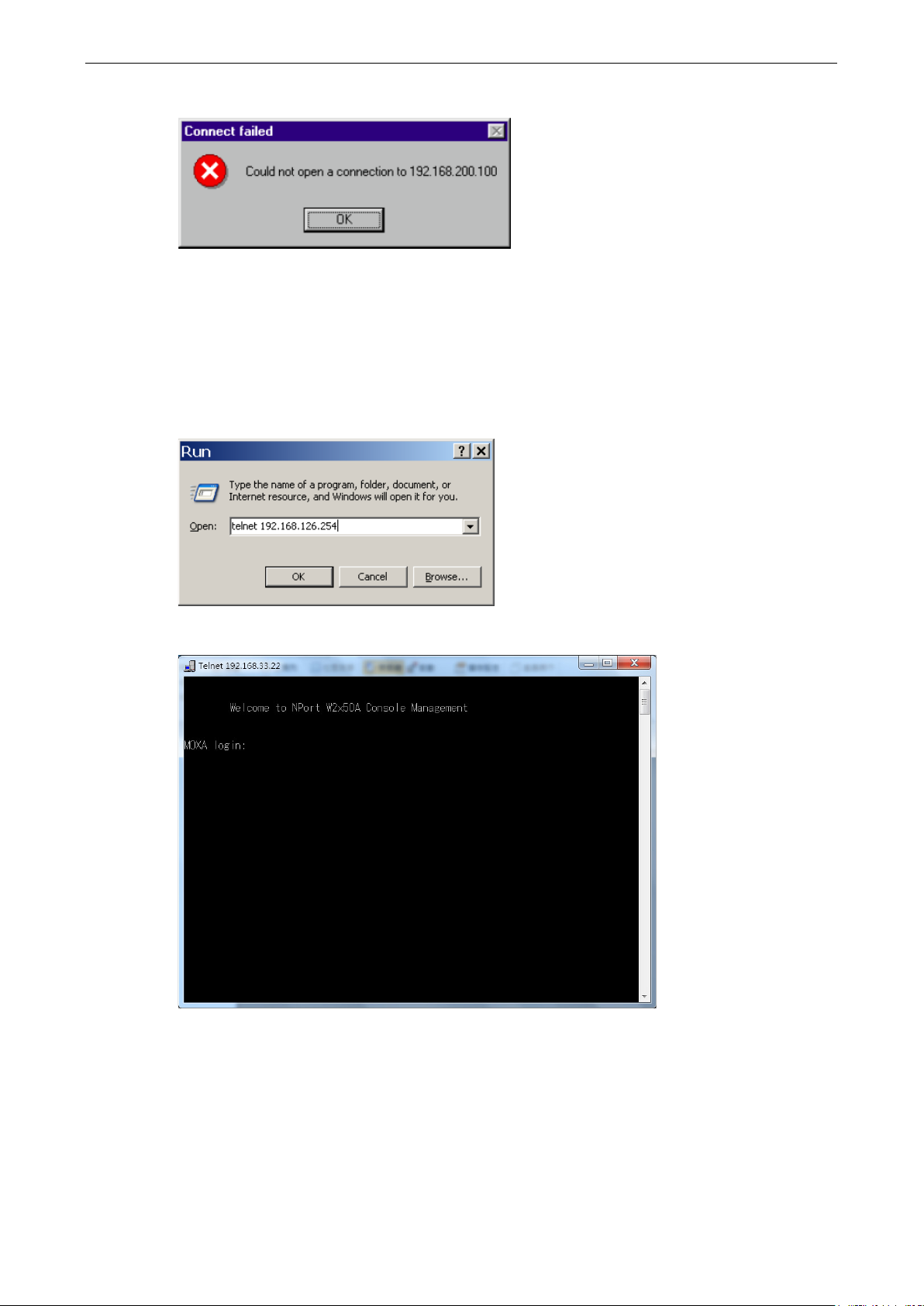
5. You will see a message indicating that the connection failed.
The NPort will automatically reboot with the new IP address. You can verify that the configuration was
successful by connecting to the new IP address with Telnet, ping, the web console, or NPort Search Utility.
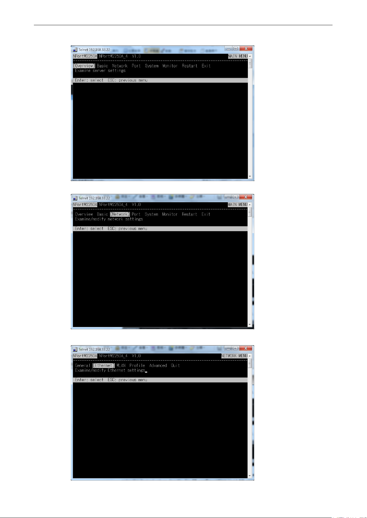
Using the Telnet Console to Assign IP Address
1. Select Run… from the Windows Start menu.
2. Enter telnet 192.168.126.254 (the NPort’s default IP address) and click [OK].
3. Enter your login account and password, then press ENTER.
Page 20
NPort W2150A/W2250A Series Initial IP Configuration
3-4
4. You will login to the Overview page.
5. Press N or use the cursor keys to select Network and press ENTER.
6. Press E or use the cursor keys to select Ethernet and press ENTER.
Page 21
NPort W2150A/W2250A Series Initial IP Configuration
3-5
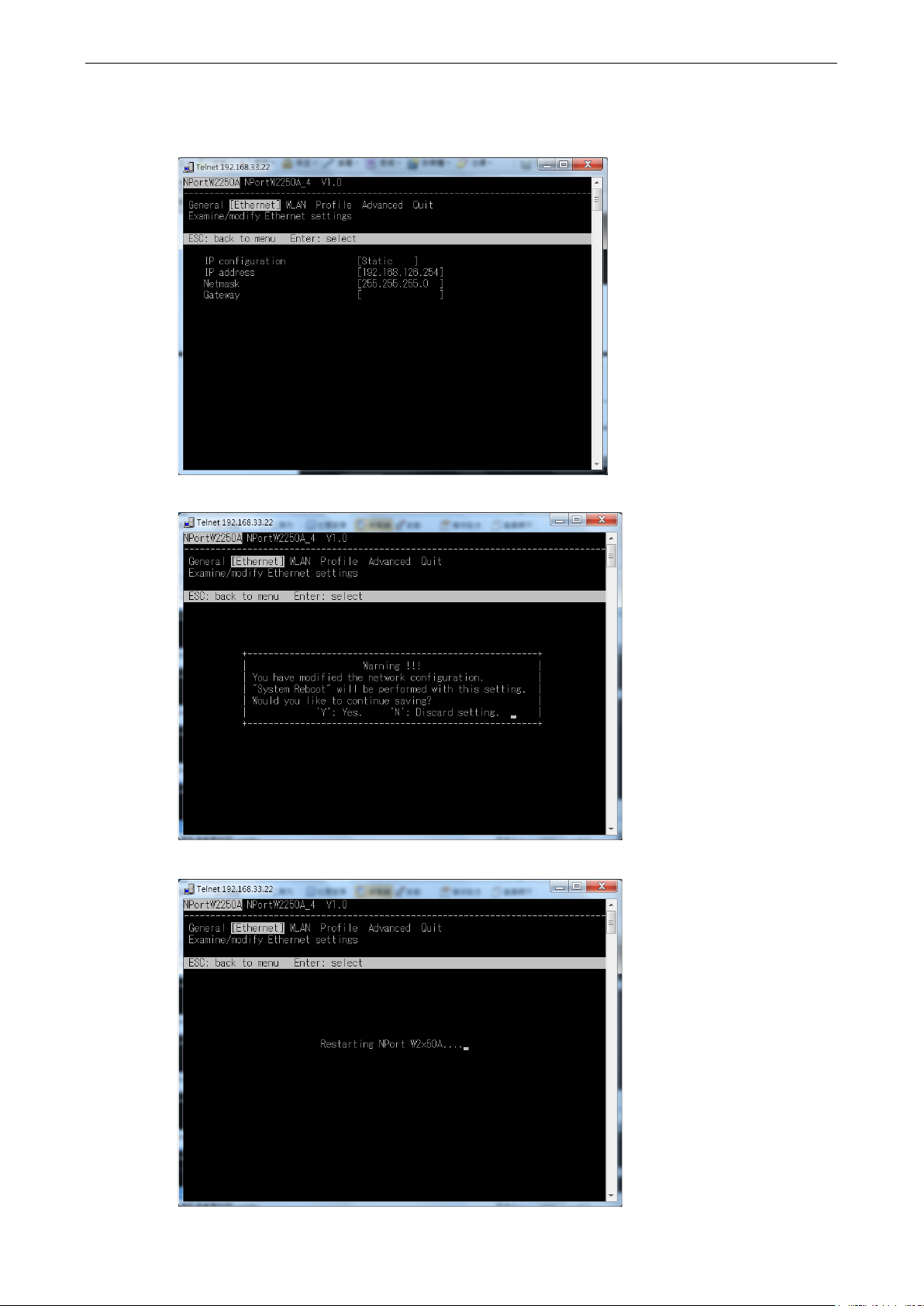
7. Use the cursor k eys to navigate between the different fields. For IP address, Netmask, and Gateway,
enter the desired values directly. For IP configuration and LAN speed, press ENTER to open a submenu
and select between the available options.
8. Press ESC to return to the menu. When prompted, press Y to save the configuration changes.
The NPort will reboot with the new I P settings. You can telnet to the new IP to login again.
Page 22
NPort W2150A/W2250A Series Initial IP Configuration
3-6
Using the Serial Console to Assign IP Address
Before using the NPort’s serial console, turn off the power and use a serial cable to connect the NPort console
port to your computer’s serial port. Port 1 on the NPort se rves as the console port. Use Port 1 connecting to the
console port with a serial-based terminal or terminal emulator program, such as Windows HyperTerminal. You
may also download PComm Lite at
serial communication parameters should be set as 19200, 8, N, 1 (19200 for baud rate, 8 for data bits, None
for parity, and 1 for stop bits). As soon as the connection is open, you will be presented with a text menu
displaying the NPort W2150A/W2250A Series general settings. Please refer to Chapter 4 for a description of the
available settings. The following instructions, we recommend using PComm Terminal Emulator, which can be
downloaded free of charge from
1. Connect your PC’s serial port to the NPort’s console port.
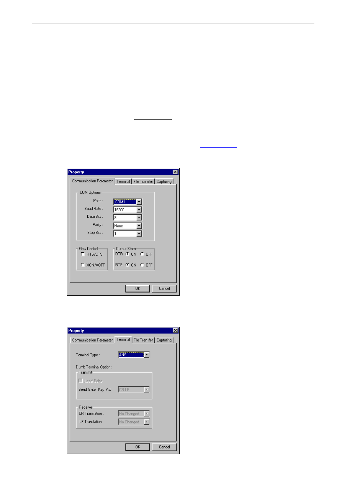
2. Open your terminal emulator program, such as Windows HyperTerminal. We recommend using PComm
Terminal Emulator, which can be downloaded for free at
3. In your terminal emulator program, configure the communication parameters for the serial port on t he PC.
The parameters should be set to 19200 for baud rate, 8 for data bits, None for parity, and 1 for stop bits.
www.moxa.com. The terminal type should be set as ANSI or VT100, and the
www.moxa.com, to carry out the configuration procedure.
www.moxa.com.
4. In your terminal emulator program, set the terminal type to ANSI or VT100. If you select Dumb Terminal
as the terminal type, some of the console functions—especially the “Monitor ” f unction—may not work
properly.
Page 23

NPort W2150A/W2250A Series Initial IP Configuration
3-7
5. Hold the grave accent key (`) down and power up the NPort.
The continuous string of grave accen t cha racters triggers the NPort to switch from data mode to console
mode.
6. The serial console will open and will be functionally identical to the Telnet console. Please refer to the Telnet
console section for instructions on how to navigate the console and co nfigure the IP settings.
Page 24

4
4. Introduction to Operation Modes
The following topics are covered in this chapter:
Overview
RealCOM Mode
RFC2217 Mode
TCP Server Mode
TCP Client Mode
UDP Mode
Pair Connection Modes
Ethernet Modem Mode
Page 25
NPort W2150A/W2250A Series Introduction to Operation Modes
4-2
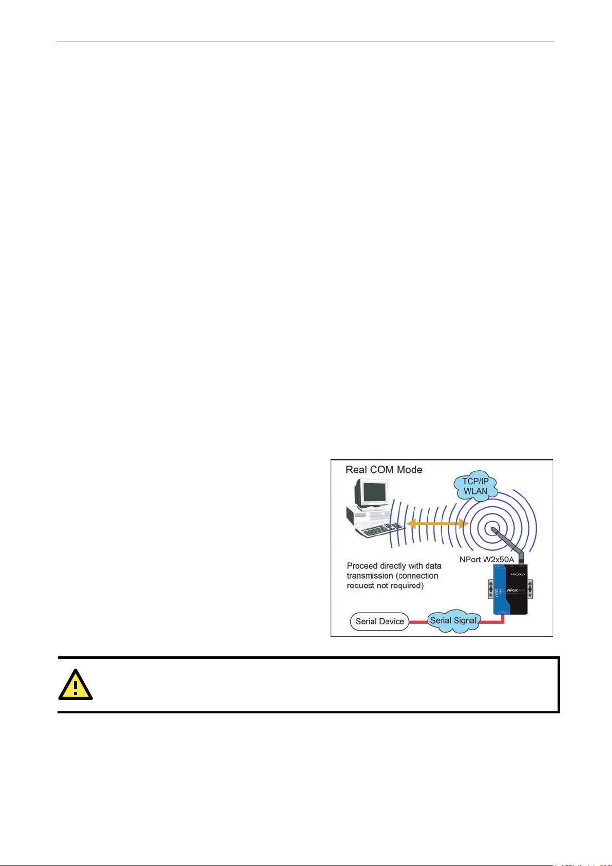
RealCOM mode is designed to work with NPort drivers
that are installed on a network host. COM drivers are
provided for Windows systems, and TTY drivers are
provided for Linux and UNIX systems. The driver
establishes a transparent connection to the attached
serial device by mapping a local serial port
NPort serial port. RealCOM mode supports up to four
simultaneous connections, so mu ltiple hosts can
collect data from the attached device at the same
time.
ATTENTION
RealCOM drivers are installed and configured
Overview
This chapter introduces the different serial port operation modes that are available on the NPort
W2150A/W2250A Series. Each serial port on the NPort is configured independently of the other ports, with its
own serial communication parameters and operation mode. The serial port’s operation mode determines how
it interacts with the network, and different modes are available to encompass a wide variety of applications and
devices.
RealCOM and RFC2217 modes allow serial-based software to access the NPort serial port as if it were a local
serial port on a PC. These modes are appropriate when your application relies on Windows or Linux software
that was originally designed for locally attached COM or TTY devices. With these modes, you can access your
devices from the network using your existing COM/TTY-based software, without investing in additional
software.
Three different socket modes are available for user-developed socket programs: TCP Server, TCP Client, and
UDP Server/Client. For TCP applications, the appropriate mode depends on whether the connection will be
hosted or initiated from the NPort serial port or from the network. The main difference between the TCP and
UDP protocols is that TCP guarantees delivery of data by requiring the recipient to send an acknowledgement
to the sender. UDP does not require this type of verification, making it possible to offer speedier delivery. UDP
also allows multicasting of data to groups of IP addresses and would be suitable for streaming media or
non-critical messaging applications such as LED message boards.
Pair Connection Slave and Master modes are designed for serial-to-serial communication over Ethernet, in
order to overcome traditional limitations with serial transmission distance.
In Ethernet Modem mode, the NPort acts as an Ethernet modem, providing a network connection to a host
through the serial port.
RealCOM Mode
to the
RealCOM mode allows you to continue using your serial communications software to access devices that are
now attached to your NPort device server. On the host, the NPort RealCOM driver automatically intercepts data
sent to the COM port, packs it into a TCP/IP packet, and red irects it to the network. At the other end of the
connection, the NPort device server accepts the Ethernet frame, unpacks the TCP/IP packet, and sends the
serial data to the appropriate device.
through NPort Windows Driver Manager.
Page 26
NPort W2150A/W2250A Series Introduction to Operation Modes
4-3
ATTENTION
In RealCOM mode, several hosts can have simultaneous access control over the NPort serial port. If necessary,
you can limit access by using the NPort’s Accessible IP settings. Plea se refer to Chapter 8 for additional
information on Accessible IP settings.
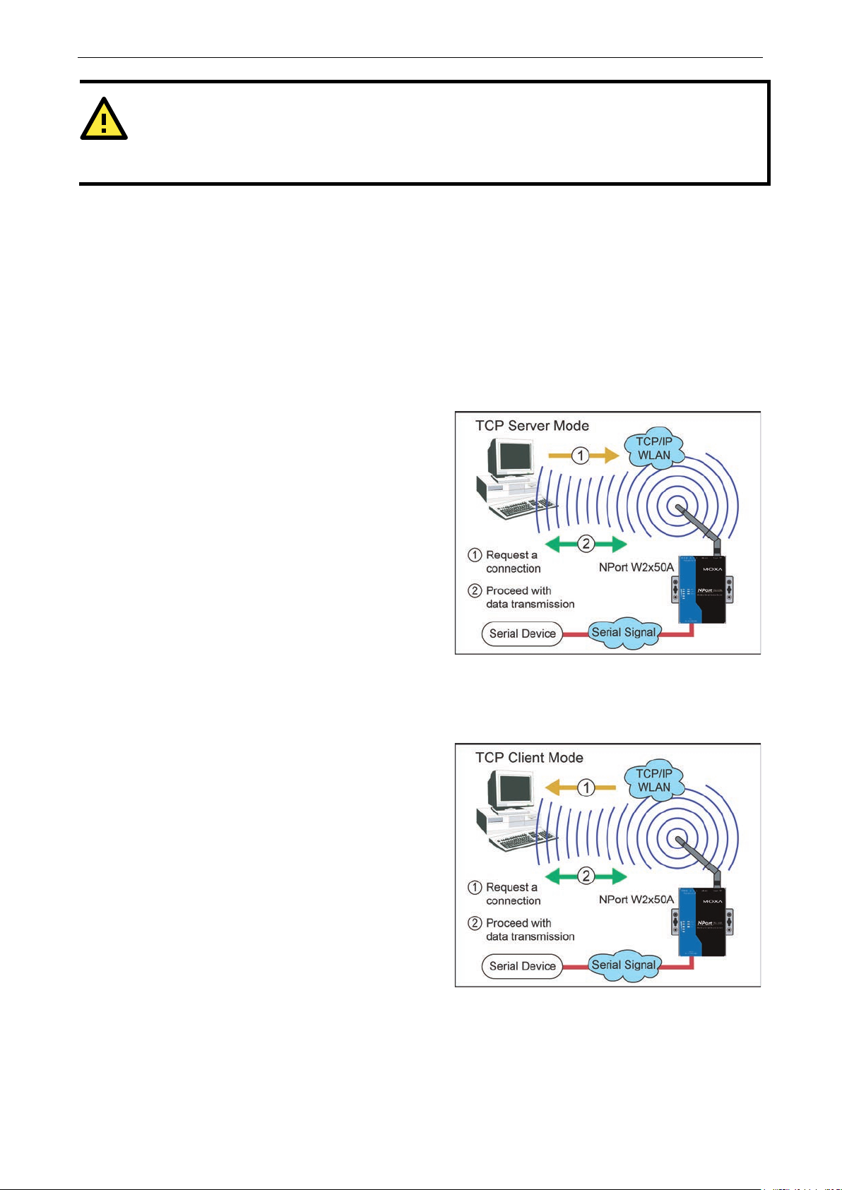
In TCP Server mode, the NPort serial port is assigned
an IP:port address that is unique on your TCP/IP
network. It waits for the host computer to establish a
connection to the attached serial d evice. This
operation mode also supports up to eight
simultaneous connections, so mu lti
collect data from the attached device at the same
time.
Data transmission proceeds as follows:
A host requests a connection to the NPort serial port.
Once the connection is established, data can be
transmitted in both direc tions
device, and from the device to the host .
In TCP Client mode, the NPort active ly establishes a
TCP connection to a specific network host when data
is received from the attached serial device. After the
data has been transferred,
automatically disconnect from the host computer
through the Inactivity time setting s. Please refer to
Chapter 7 for details on these parameters.
Data transmission proceeds as follows:
The NPort requests a connection fr om the host.
The connect
transmitted in both directions between the host and
device.
RFC2217 Mode
RFC-2217 mode is similar to RealCOM mode, since it relies on a driver to transparently map a virtual COM port
on a host computer to a serial port on the NPort. The RFC2217 standard defines general COM port control
options based on the Telnet protocol and supports one connection at a time. Third party drivers supporting
RFC-2217 are widely available on the Internet and can be used to implement virtual COM mapping.
TCP Server Mode
ple hosts can
—from the host to the
TCP Client Mode
the NPort can
ion is established and data can be
Page 27
NPort W2150A/W2250A Series Introduction to Operation Modes
4-4
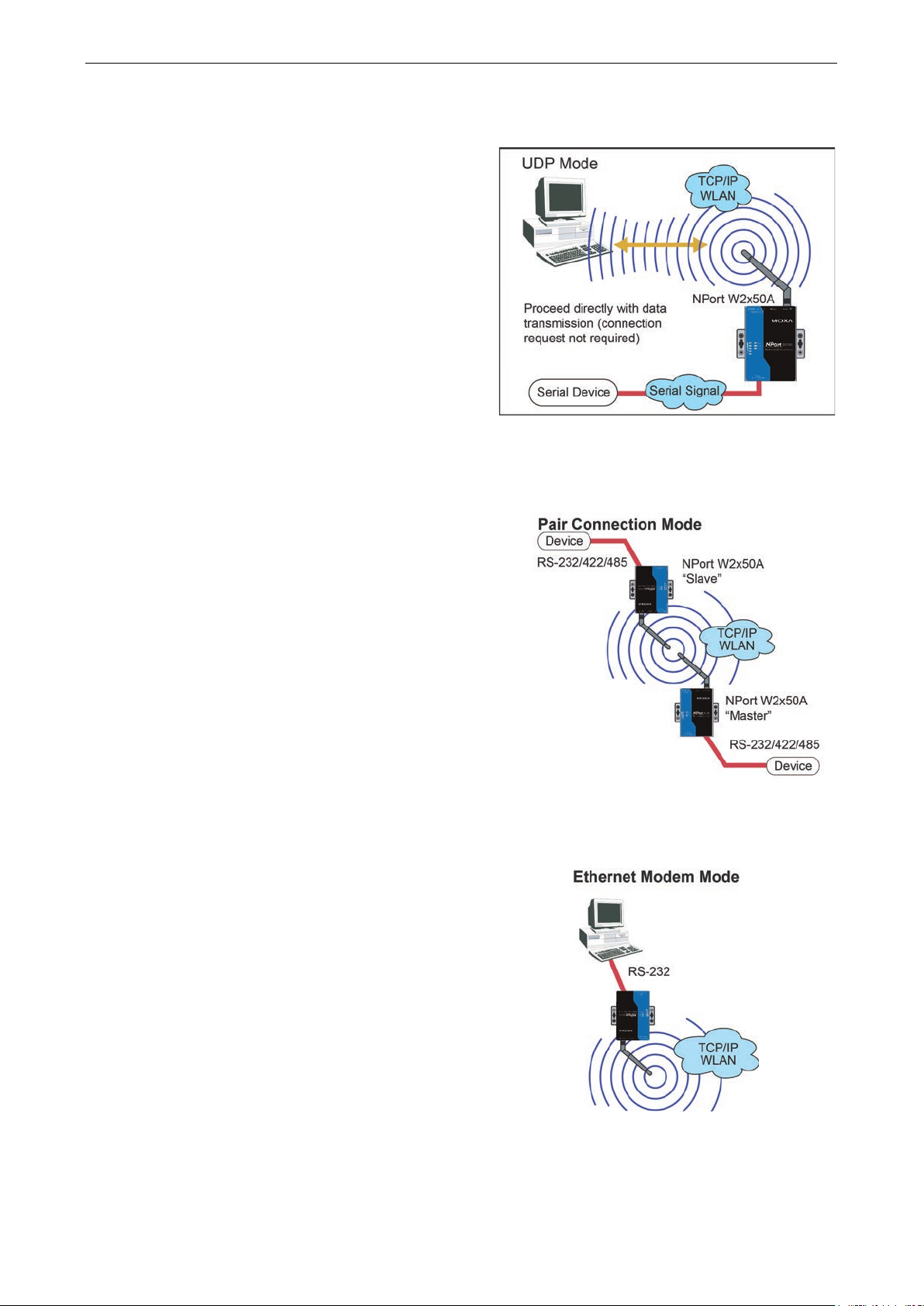
UDP is similar to TCP but is faster and more efficient.
Data can be broadcast to or received from multiple
network hosts. However, UDP does no t suppo
verification of data and would not be suitable for
applications where data integrity is critical. It is ideal
for message display applications.
Pair Connection Master and Slave modes connect two
NPort device servers over a
serial
communication. A device attached to one NPort can
then communicate transparently to a device attached
to the other NPort, as if the two devices were
connected by a serial cable. Both data and modem
control signals are exchanged, except for DCD signals.
This can be used to overcome tradition al limitations
with serial communication distance and introduces
many new possibilities for serial-based device control.
Ethernet Modem mode is designed for use with legacy
operating systems, such as MS
support TCP/IP Ethernet. By connecting the prop er ly
configured NPort serial port to the MS-DOS computer’s
serial port, it is possible to use lega cy software to
transmit data over the Ethernet when the software was
originally designed to transmit data over a modem.
UDP Mode
rt
Pair Connection Modes
network for serial-to-
Ethernet Modem Mode
-DOS, that do not
Page 28

5
5. Web Console: Basic Settings
The following topics are covered in this chapter:
Overview
Basic Settings
Page 29
NPort W2150A/W2250A Series Web Console: Basic Settings
5-2
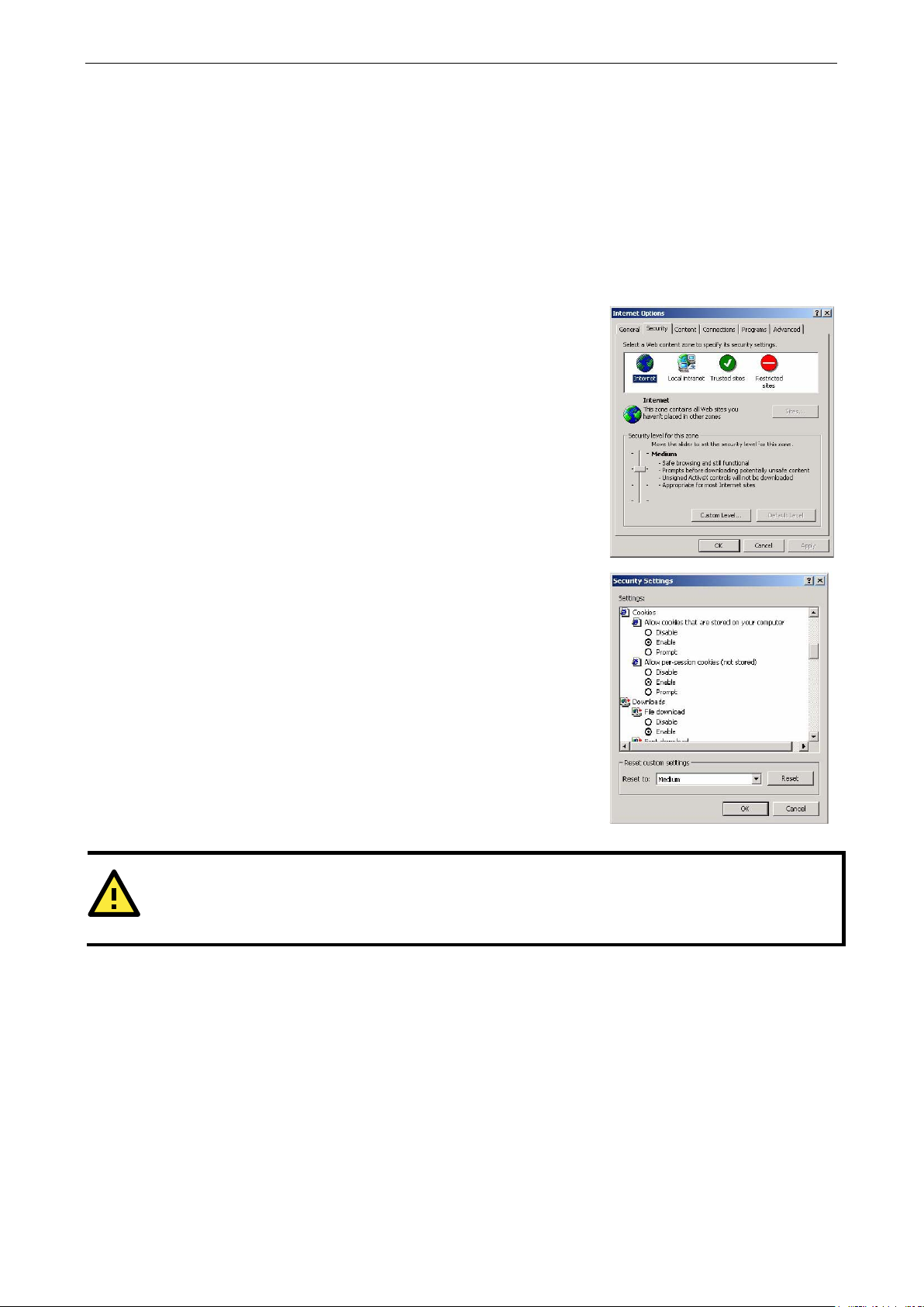
In order to use the web console, you will need to have cookies e nabled
for your browser. Please note that the web console uses cookies only for
password transmission. For Internet Explorer, cookies can be enabled
by right
selecting Properties from the context menu.
On the Security tab, click “Custom Level…” and enable these two items:
Allow
Allow per
ATTENTION
If you are not using Internet Explorer, cookies are usually enabled through a web browser setting such as
“allow cookies that ar
Overview
This chapter introduces the NPort w eb console and explains how to configure the basic settings.
The NPort can be configured from anywhere on the network through its web console. Simply point the browser
to the device server’s IP address to open the web console. Network settings, operation mode, and other items
can all be configured through the browser.
Web Browser Settings
-clicking the Internet Explorer icon on your desktop and
cookies that are stored on your computer.
-session cookies (not stored).
e stored on your computer” or “allow per-session cookies.”
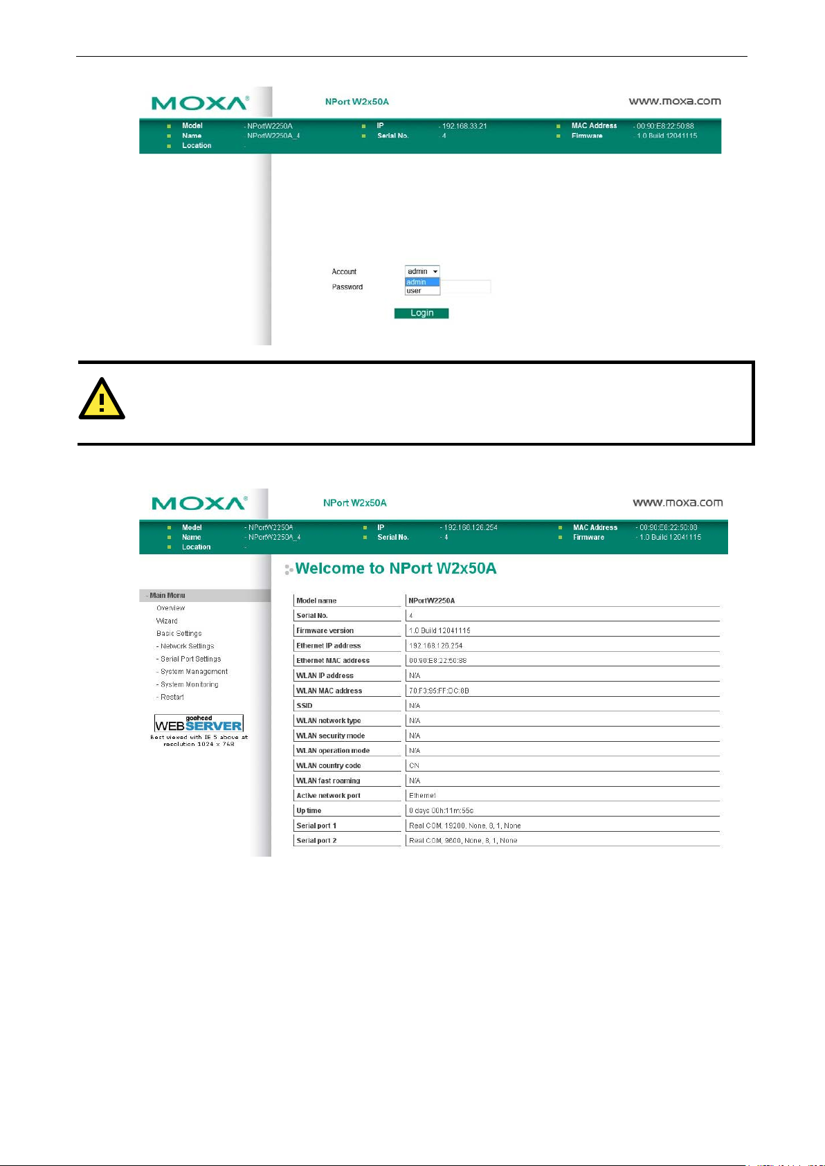
Navigating the Web Console
To open the web console, enter your dev ice server’s IP address in the website address line. If you are
configuring the NPort for the first time over an Ethernet cable, you will use the default IP address,
192.168.126.254.
There are two account types: admin and user. If you enter the system with admin account, you will have the
right to read and write. If you enter the system with user account, you will only have the right to read.
If prompted, enter the console password. You will only be prompted for a password if you have enabled
password protection on the device server. The password will be transmitted with MD5 encryption over the
Ethernet.
Page 30
NPort W2150A/W2250A Series Web Console: Basic Settings
5-3
ATTENTION
If you have forgotten the password, you can use the reset button to load factory defaults, but this will erase all
previous configuration information.
The web console will appear as shown below.
Settings are presented on pages that are organized by folder. Select the desired folder in the left navigation
panel to open that page. The page will be displayed in the main window on the right. Certain folders can be
expanded by clicking the adjacent “–” symbol.
For example, if you click Basic Settings in the navigation panel, the main window will show a page of basic
settings that you can configure.
After you have made changes on a page, you must click [Submit] in the main window before jumping to
another page. Your changes will be lost if you do not click [Submit].
Once you click [Submit] b utton, the device server will reboot and with a beep alarm.
Page 31

NPort W2150A/W2250A Series Web Console: Basic Settings
5-4
This is an optional free text field to help you differentiate one d evice server from another . It
This is an optional free text field to help you differentiate one d evice server from another . It
Basic Settings
On the Basic Settings page, you can configure Server name, Server location, Time zone (24-hour),
Local time, and Time server.
Server Name
Default NPortW2150A_<serial no.> or NPortW2250A_<serial no.>
Options free text (e.g., “Server 1”)
Description
does not affect operation of the NPort device server.
Server Location
Default
Options free text (e.g., “Bldg 1, 2nd Floor”)
Description
does not affect operation of the NPort device server.
Time Zone
Default (GMT)Greenwich Mean Time
Options (GMT)Greenwich Mean Time
(GMT-01:00)Azores, Cape Verde Is.
(GMT-02:00)Mid-Atlantic etc.
Description This field shows the currently selected time zone and allows you to select a different time
zone.
Page 32

NPort W2150A/W2250A Series Web Console: Basic Settings
5-5
time clock that allows you to add time information to functions
ATTENTION
There is a risk of explosion if the real
The real time clock is powered by a lithium battery. We strongly recommend that you obtain assistance from
a Moxa support engineer before replacing the battery. Please contact the Moxa RMA service team if you need
to change the battery.
Local Time
Default
Options Date (yy:mm:dd), Time (hh:mm:ss)
Description The NPort has a built-in real-
such as the automatic warning e-mail or SNMP trap. This field shows the cu rrent time
according to the NPort’s built-in real-time clock. This is not a live field, s o you will need to
refresh the browser to get an updated rea ding.
Change the correct date or time, and click [Submit]. The change will take effect directly, and
shows Basic Setting OK!.
-time clock battery is replaced incor rectly!
Time Server
Default
Options IP address or do ma in name (e.g., “192.168.1.1” or “time.nist.gov”)
Description This optional field specifies your time server’s IP address or domain name, if a time server is
used in your network. The NPort supports SNTP (RFC-1769) for automatic time calibration.
The device server will request time information from the specified time server every 10
minutes.
Page 33

6
6. Web Console: Network Settings
The following topics are covered in this chapter:
Overview
Network Settings
Genera l Settings
Ethernet Settings
WLAN Settings
Advanced Settings
Page 34

NPort W2150A/W2250A Series Web Console: Network Settings
6-2
Overview
This chapter explains how to configure all settings located under the Network Settings folder in the NPort web
console.
Network Settings
General Settings
On the General Settings page in the Network Settings folder, you can modify DNS server 1 and 2.
DNS Server 1 and 2
Default
Options IP address (e.g., “192.168.1.1”)
Description This field is for the DNS server’s IP address, if applicable. With the DNS server configured, the
NPort device server can use domain names instead of IP addresses to access hosts.
Domain Name System (DNS) is how Internet domain names are identified and translated into
IP addresses. A domain name is an alphanumeric name, such as www.moxa.com, that it is
usually easier to remember than the numeric IP address. A DNS server is a ho st that
translates a text-based domain name into an IP address in order to establish a TCP/IP
connection. When the user wants to visit a particular website, the user’s computer sends the
domain name (e.g., www.moxa.com) to a DNS server to request that website’s nu me ric IP
address. When the IP address is received from the DNS server, the user’s computer uses that
information to connect to the website’s web server.
The NPort will play the role of a DNS client, actively querying the DNS server for the IP
address associated with a particular domain name.
Page 35

NPort W2150A/W2250A Series Web Console: Network Settings
6-3
network. Choose a proper IP address that is unique and valid in your network environment.
Ethernet Settings
On the Ethernet Settings page in the Network Settings folder, you can modify IP configuration, IP
address, Netmask, and Gateway.
You must assign a valid IP address to the NPort before it will work in your network envi ronment. Your network
system administrator should provide you with an IP address and related settings for your network. The IP
address must be unique within the network; otherwise the NPort will not have a valid connection to the network.
First-time users should refer to Chapter 3, “Initial IP Address Configuration,” for more information.
IP Configuration
Default Static
Options Static, DHCP, DHCP /BO OTP, BOOTP
Description This field determines how the NPort’s IP add ress will be assigned.
Static: IP address, netmask, and gateway are user-defined.
DHCP: IP address, netmask, gateway, DNS, and time server are assigned by DHCP server.
DHCP/BOOTP: IP address, netmask, gateway, DNS, and time server are assigned by DHCP
server. IP address is assigned by BOOTP server if DHCP server does not respond.
BOOTP: IP address is assigned by BOOTP server.
IP Address
Default 192.168.126.254
Options IP address (e.g., “192.168.1.1”)
Description This field is for the IP address that will be assigned to your NPort device server. An IP address
is a number assigned to a network device (such as a computer) as a permanent address on
the network. Computers use the IP address to identify and talk to each other over the
If your device server will be assigned a dynamic IP address, set the “IP configuration”
parameter appropriately.
Page 36

NPort W2150A/W2250A Series Web Console: Network Settings
6-4
ATTENTION
In dynamic IP environments, the NPort will send 3 requests every 30 seconds to the DHCP or BOOTP server
until the network settings have successfully been assigned. The first request will time out after one second; the
second request will time out after thr ee seconds, and the third request wi ll timeout after five second. If the
DHCP or BOOTP server is unavailable, the NPort will use the factory default network settings.
Netmask
Default 255.255.255.0
Options Netmask setting (e.g., “255.255.0.0”)
Description This field is for the subnet mask. A subnet ma sk represents all of the network hosts at one
geographic location, in one building, or on the same lo cal area network. When a packet is
sent out over the network, the NPort device server will use the subnet mask to check whether
the desired TCP/IP host specified i n the packet is on the local network se gment. If the
address is on the same network segment as the device server, a connect ion is established
directly from the device server. Otherwise, the connection is established through the
gateway as specified in the “Gateway” parameter.
Gateway
Default
Options IP address (e.g., “192.168.1.1”)
Description This field is for the IP address of the gateway, if applicable. A gateway is a network computer
that acts as an entrance to another network. Usually , the computers that control traffic
within the network or at the local Internet service provider are gateway nodes. The NPort
device server needs to know the IP address of the default gateway computer in order to
communicate with the hosts outside the local network environment. Consult your network
administrator if you do not know how to set this parameter.
WLAN Settings
WLAN
Page 37

NPort W2150A/W2250A Series Web Console: Network Settings
6-5
WLAN environment. If
The WLAN page is located under WLAN Settings in the Network Settings folder. You can modify IP
configuration, IP address, Netmask, and Gateway for your WLAN.
The NPort W2150A/W2250A Series supports IEEE 802.11a/b/g wireless network interfaces. The supported IP
configurations are static and dynamic (BOOTP, DHCP, or BOOTP+DHCP). Users can set up the IP configuration
with the serial console, or the Web/Telnet consoles through the NPort’s Ethernet interface. For detailed
information about configuring IP configuration, IP address, Netmask, and Gateway, see the previous
section, Ethernet Config u ration.
IP Configuration
Default Static
Options Static, DHCP, DHCP /BO OTP, BOOTP
Description This field determines how the NPort’s IP add ress will be assigned.
Static: IP address, netmask, and gateway are user-defined.
DHCP: IP address, netmask, gateway, DNS, and time server are assigned by DHCP server.
DHCP/BOOTP: IP address, netmask, gateway, DNS, and time server are assigned by DHCP
server. IP address is assigned by BOOTP server if DHCP server does not respond.
BOOTP: IP address is assigned by BOOTP server.
IP Address
Default 192.168.127.254
Options IP address (e.g., “192.168.1.1”)
Description This field is for the IP address that will be assigned to your NPort device server. An IP address
is a number assigned to a network device (such as a computer) as a permanent address on
the network. Computers use the IP address to identify and talk to each other over the
network. Choose a proper IP address that is unique and valid in your
your device server will be assigned a dynamic IP address, set the “IP configuration”
parameter appropriately.
Netmask
Default 255.255.255.0
Options Netmask setting (e.g., “255.255.0.0”)
Description This field is for the subnet mask. A subnet mask represents all of the network hosts at one
geographic location, in one building, or on the same local area network. When a packet is
sent out over the network, the NPort device server will use the subnet mask to check whether
the desired TCP/IP host specified in the packet is on the local network segment. If the
address is on the same network segment as the device server, a connection is established
directly from the device server. Otherwise, the connection is established through the
gateway as specified in the “Gateway” parameter.
Gateway
Default
Options IP address (e.g., “192.168.1.1”)
Description This field is for the IP address of the gateway, if applicable. A gateway is a network computer
that acts as an entrance to another network. Usually, the computers that control traffic
within the network or at the local Internet service provider are gateway nodes. The NPort
device server needs to know the IP address of the default gateway computer in order to
communicate with the hosts outside the local network environment. Consult your network
administrator if you do not know how to set this parameter.
Page 38

NPort W2150A/W2250A Series Web Console: Network Settings
6-6
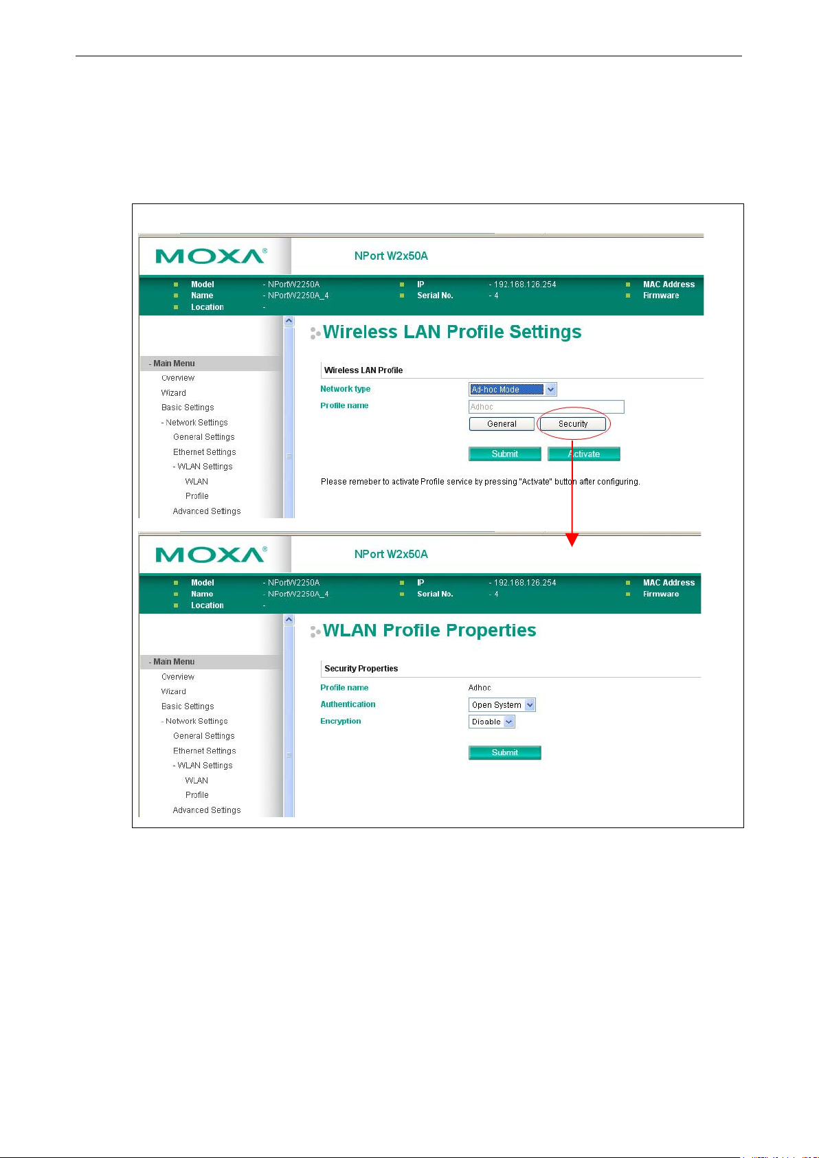
Profile
The Profile page is located under WLAN Settings in the Network Settings folder. This is where you
configure the NPort for Ad-hoc or Infrastructure operation. Different settings are available depending on
whether you select Ad-hoc Mode or Infrastructure Mode.
Page 39

NPort W2150A/W2250A Series Web Console: Network Settings
6-7
After setting the Network type, you will need to adjust the General and Security settings for
Network Type
Default Infrastructure Mode
Options Infrastructure Mode, Ad-hoc Mo de
Description This field specifies whether the NPort will operate in Ad-hoc or Infrastructure Mode. For all
wireless networking devices, there are two possible modes for communication with another
wireless device. Devices that a re configured for Ad-hoc Mode automatically detect and
communicate directly with each other a nd do not require a wireless access point (AP) or
gateway. Wireless devices that are configured for Infrastructure Mode do not communicate
directly with each other, but through a wireless access point (AP).
Devices must be configured for the same mode in order to communicate w ith each other.
Devices in Ad-Hoc Mode will only recognize other devices in Ad-Hoc Mode, and likewise for
devices in Infrastructure Mode.
Example of Ad-Hoc Mode
Example of Infrastructure Mode
the profile. In Ad-hoc Mode, only one profile is available. In Infrastructure Mode, three
profiles can be defined.
Page 40

NPort W2150A/W2250A Series Web Console: Network Settings
6-8
General Settings for WLAN Profile
The General page is opened thro u gh the Profile page, under WLAN Settings in the Network Settings
folder. You can type a profile name to help you differentiate one profile from another. It does not affect
operation of the NPort. After selecting Ad-hoc or Infrastructure Mode, click [General] to open the General
page for the selected profile. In Ad-hoc Mode and Infrastructure Mode, only one profile is available.
In Ad-hoc Mode
Page 41

NPort W2150A/W2250A Series Web Console: Network Settings
6-9
In Infrastructure Mode
On the General page, you can configure Profile name, Operation mode, and SSID. Additional settings are
also available depending on whether you select Ad-hoc Mode or Infrastructure Mode.
Profile Name
Default Ad-hoc (in Ad-hoc Mode)
Infrastructure (in Infrastructure Mode)
Options free text (e.g., “Primary Connection”)
Description This is a free text field to help you differentiate one profile from another. It does not affect
operation of the NPort.
Page 42

NPort W2150A/W2250A Series Web Console: Network Settings
6-10
es
from the RF band used by 802.11b and 802. 11g. Cons equentl y, 802.11a de vices will not be
Operation Mode
Default 802.11b/g for Ad-Hoc Mode.
Auto, 802.11b/g, and 802.11a for Infrastructure Mode.
Options Auto, 802.11a, 802.11b/g
Description This field determines which wireless standard will be used by the selected p rofile. 802.11a,
802.11b, and 802.11g are supported.
Auto: In Ad-hoc Mode, the NPort will scan the 2.4G wireless band and will automatically
select the appropriate wireless standard for communication with any other wireless devic
that are detected. In Infrastructure Mode, the NPort will automatically select between
802.11a, 802.11b and 802.11g according to the settings of the AP.
802.11a: This setting is only availab le in Infrastructure Mode. The Unlic ensed National
Information Infrastructure (UNII) 5 GHz band is used for communication, which is different
able to communicate with 802.11b or 802.11g devices. (Multi-mode 802.11a/b/g APs or
client adapters can be used to resolve this.) Transmission rates up to 54Mbps are supported.
802.11b/g: This option means our device will support for 802.11b or 802.11g.
802.11b: This is the well-known “Wi-Fi” standard, also referred to as “802.11 High-Rate
(HR)”. Wireless communication is in the 2.4 GHz ISM band, using the DSSS spread spectrum
transmission scheme. 802.11b supports data rates of 1 Mbps, 2 Mbps, 5.5 Mbps, and 11
Mbps.
802.11g: This is currently the most widely used standard for wireless LANS and is sometimes
referred to as “54g™”. Communication is in the 2.4 GHz ISM band and uses Orthogonal
Frequency Division Multiplexing (OFDM). Data rates up to 54 Mbps are supported.
SSID
Default Default
Options free text (e.g., “Coffeeshop WLAN”)
Description This field specifies the SSID, or name, of the wireless network (SSID) that will be used by the
NPort. Wireless devices must use the same SSID in order to communicate with each other.
Channel (Ad-hoc mode only)
Default 1
Options 1, 2, 3, 4, 5, 6, 7, 8, 9, 10, 11
Description This field is for Ad-Hoc Mode only and specifies the radio channel to us e f or the wireless
network.
Page 43

NPort W2150A/W2250A Series Web Console: Network Settings
6-11
44, 48, 52, 56, 60, 64, 100, 104, 108, 112, 116, 120, 124, 128, 132, 136, 140,
Fast Roaming (Infrastructure mode only)
Default Disable
Options Disable, Enab l e
Description This field is only available in Infrastructure Mode and is used to specify the
W2150A/W2250A roaming behavior. Roaming is the ability to connect to different APs so
wireless communication is not confined to one area or one particular AP. The
W2150A/W2250A will only roam between APs, as specified by the SSID.
Disable: Fast Roaming function will be disabled.
W2150A/W2250A will scan all available channels and roam between APs as specified by the
SSID. It scans the channel when booting up and will associate with the highest signal
strength AP. Only when the associated A P is loses, then it will re-associate again.
Enable: Fast Roaming function will be enabled.
NPort W2150A/W2250A will only scan the pre-defined "Scan Channels - 1, Scan Channels
- 2 & Scan Channels – 3" and roam between APs as specified by the SSID.
It scans the channel and will associate with the highest signal strength AP. It also scans the
channel regularly and will re-associate with the highest signal strength AP (if there is) by
automatically.
Scan channels – 1, Scan channels – 2, Scan channels – 3 (Infrastructure mode
only)
Default N/A
Options 1 through 14, 36, 40,
149, 153, 157, 161
Description This field is for fast roaming under Infrastructure Mode and specifies the radio channel to use
for the wireless network. Choose the channel according to the factory setting of AP.
Extend disconnect detection (This function is supported from firmware v1.3)
Default Disable
Options Disable, Enab l e
Description The function is used to check if AP disconnect with Device when enable fast roaming. It will
re-scan all test signal and connect to the AP with greatest signal when finding the connection
disconnects.
Page 44
NPort W2150A/W2250A Series Web Console: Network Settings
6-12
Security Settings for WLAN Profile
The Security page is opened through the Profile page , under WLAN Settings in the Network Settings
folder. After selecting Ad-hoc or Infrastructure Mode, click [Security] to open the Security page for the
selected profile. In Ad-hoc Mode, only one profile is available, whereas three profiles are available in
Infrastructure Mode.
In Ad-hoc Mode
Page 45

NPort W2150A/W2250A Series Web Console: Network Settings
6-13
In Infrastructure Mode
You will need to configure Authentication and Encryption. These settings must match the settings on the
wireless device at the other end of the connection (such as the AP). Different settings and options are available
depending on how Authentication and Encryption are configured.
Page 46

NPort W2150A/W2250A Series Web Console: Network Settings
6-14
Open System: The NPort will simply announce a desire to associate with another station or
WPA: This is a managed authentication option that is only available in Infrastructure Mode.
Authentication
Default Open System
Options Open System, Shared Key, WPA, WPA-PSK, WPA2, WPA2-PSK
Description This field specifies how wireless devices will be authenticated. Only authenticated devices will
be allowed to communicate with th e NPort. If a RADIUS server is used, this setting must
match the setting on the RADIUS server .
access point. No authenticatio n is required. For Ad-hoc Mode, this is the only option for
authentication, since Ad-hoc Mode was designed for open communication.
Shared Key: This option is only available in Infrastructure Mode. Authentication involves a
more rigorous exchange of frames to en sure that the requesting station is a uthentic. WEP
encryption is required.
WPA was created by the Wi-Fi Alliance, the industry trade group that owns the Wi -Fi
trademark and certifies devices with the Wi-Fi name. It is based on Draft 3 of the IEEE
802.11i standard. Each user uses a unique key for authentication, distributed from an IEEE
802.1X authentication server, also known as a RADIUS server. This option is also referred to
as WPA Enterprise Mode, since it is intended to meet rigorous enterprise security
requirements. Tunneled authentication is supported, depending on the EAP method selected.
WPA-PSK: This is an unmanaged authentication option that is only available in Infrastructure
Mode. Instead of a unique key for each user, a pre-shared key (PSK) is manually entered on
the access point to generate an encryption key that is shared among all users. Consequently,
this method does not scale well for enterprise. A PSK that uses a mix of letters, numbers and
non-alphanumeric characters is recommended. This option is also ref erred to as WPA
Personal Mode, since it is designed f or the needs and capabilities of smal l home and office
WLANs.
WPA2: This is a managed authentication option that is only available in Infrastructure Mode.
WPA2 implements the mandatory elements of 802.11i. Supported encryption algorithms
include TKIP, Michael, and AES-based CCM P, w hich is considered fully secure. Since March
13, 2006, WPA2 has been mandatory for all Wi-Fi-certified devices. This option may also be
referred to as WPA Enterprise Mode. Tunneled authentication is supported, depending on the
EAP method selected.
WPA2-PSK: This is an unmanaged authentication option that is only available in
Infrastructure Mode. It employs WP2 encryption algorithms but relies on a PSK for
authentication. A PSK that uses a mix of letters, numbers and non-alphanumeric characters
is recommended. This option can also be referred to as WPA Personal Mode.
Page 47

NPort W2150A/W2250A Series Web Console: Network Settings
6-15
bit
packet key mixing function
bit
Encryption
Default Disable
Options Disable, WEP, TKIP, AES-CCMP
Description This field specifies the type of encryption to use during wireless communication. Different
encryption methods are available depending on the Aut hentication setting. Also, each
encryption method has its own set o f parameters that may also require configuration.
Disable: No encryption is applied to the data during wireless communication. This option is
only available if Authentication is set to Open System.
WEP: Wired Equivalent Privacy (WEP) is only available for Open System and Shared Key
authentication methods. Data is encrypted according to a key. The NPort supports both 64
and 128-bit keys. This method may deter casual snooping but is not considered very secure.
TKIP: Temporal Key Integrity Protocol (TKIP) is only available for WPA, WPA2, WPA-PSK, and
WPA2-PSK authentication methods. TKIP is part of a draf t stan d ard from the IEEE 802.11i
working group and utilizes the RC4 stream cipher with 128-bit keys for encryption and 64keys for authentication. TKIP improves on WEP by adding a perto de-correlate the public initialization vectors (IVs) from weak keys.
AES-CCMP: This is a powerful encryption method that is only available for WPA, WPA2,
WPA-PSK, and WPA2-PSK authentication methods. Advanced Encryption Standard (AES) is
the block cipher system used by the Robust Secure Network (RSN) protocol and is equivalent
to the RC4 algorithm used by WPA. CCMP is the security protocol used by AES, equivalent to
TKIP for WPA. Data undergoes a Message Integrity Check (MIC) using a well-known and
proven technique called Cipher Block Chaining Message Authentication C ode (CBC-MAC).
The technique ensures that even a one-bit alteration in a message produces a dramatically
different result. Master keys are not used directly but are used to derive other keys, each of
which expire after a certain amount of time. Messages are encrypted using a secret 128key and a 128-bit block of data. The encryption process is complex, but the administrator
does not need to be aware of the intricacies of the computations. The end result is encryption
that is much harder to break than even WPA.
PSK Passphrase
Default
Options free text (e.g., “This is the WLAN passphrase”)
Description This field is only available for WPA-PSK and WPA2-PSK authentication methods. If the NPort’s
passphrase does not match the AP’s passphrase, the connection will be denied. A PSK of
sufficient strength—one that uses a mix of letters, numbers and non-alphanumeric
characters—is recommended.
Page 48

NPort W2150A/W2250A Series Web Console: Network Settings
6-16
Security Settings for WEP Encryption
When Encryption is set to WEP on the Security page for the WLAN profile, you will be able to configure WEP
key length, WEP key index, and WEP key source. Other settings will be displayed depending on how WEP
key source is configured.
WEP Key Length
Default 64bits
Options 64bits, 128bits
Description This field specifies the length of the WEP key. 64bits is the industry standard for WEP, but
128bits provides better protection.
WEP Key Index
Default 1
Options 1 through 4
Description This field specifies the primary WEP key to use for the WLAN.
WEP Key Source
Default Manual
Options Manual, Generate WE P keys by passphrase
Description This field specifies whether the WEP key will be generated manually or through a
user-specified passphrase. A passphrase is eq uiva le nt to a free-text password that will be
used to generate the WEP key. A passphrase is typically easier to remember and enter than
a long and complicated WEP key.
WEP Passphrase
Default
Options free text (e.g., “This is the WEP passphrase”)
Description This field is only available if WEP key source is set to “Generate WEP keys by passphrase”. A
standard hexadecimal password will be generated using the supplied passphrase. For
example, if “404tech” is entered, the WEP key will be “DB971608E942FC39BD89FC4ADB”.
Page 49

NPort W2150A/W2250A Series Web Console: Network Settings
6-17
This field is only available if WEP key source is set to “Manual”. It s pecifies the format you will
WEP Key Format
Default ASCII
Options ASCII, HEX
Description
use to enter the WEP key.
WEP Key 1 Through 4
Default
Options free text in ASCII or HEX
Description These fields are only available if WEP key source is set to “Manual”. Enter each WEP key in
ASCII or HEX as specified in WEP key format. The number of characters required for each key
depends on WEP key length and WEP key format.
WEP Key Length WEP Key Format Key Length
64bits ASCII 5 characters
HEX 10 characters
128bits ASCII 13 characters
HEX 26 characters
Security Settings for WPA, WPA2
Page 50

NPort W2150A/W2250A Series Web Console: Network Settings
6-18
When WPA or WPA2 is used for authentication, you wil l also need to configure EAP method in the Security
settings for the WLAN profile. Other settings will also be displayed depending on how EAP method is
configured.
There are two parts to WPA and WPA2 security, authentication and data encryption.
• Authentication occurs before access is granted to a WLAN. Wireless clients such as the NPort
W2150A/W2250A Series are first authenticated by the AP according to the authenticati on protocol used by
the RADIUS server. Depending on the WLAN security settings, an EAP tunnel can be used to scramble the
username and password that is submitted for authentication purposes.
• Encryption occurs after WLAN access has been granted. For all wireless d evices, data is first encrypted
before wireless transmission, using mutually agreed-upon encryption protocol.
Page 51

NPort W2150A/W2250A Series Web Console: Network Settings
6-19
tify the NPort. The NPort’s
EAP Method
Default PEAP
Options TLS, PEAP, TTLS, LEAP
Description This field specifies the EAP method to use for authentication. Four methods are supported.
TLS: Transport Layer Security (TLS) was created by Microsoft and accepted by the IETF as
RFC 2716: PPP EAP TLS Authentication Protocol. Passwords and tunneled authentication are
not used. A user certificate and user private key are used to iden
user certificate and user private key must already be installed on the RADIUS server.
PEAP: Protected Extensible Authentication Protocol (PEAP) is a proprietary protocol which
was developed by Microsoft, Cisco and RSA Security.
TTLS: Tunneled Transport Layer Security (TTLS) is a proprietary protocol which was
developed by Funk Software and Certicom, and is supported by Agere Systems, Proxim, and
Avaya. TTLS is being considered by the IETF as a new standard. For more information on
TTLS, read the draft RFC EAP Tunneled TLS Authentication Protocol.
LEAP: Lightweight Extensible Authentication Protocol (LEAP) is a proprietary protocol which
was developed by Cisco. LEAP doesn’t check certificate during the authe ntication process.
Tunneled Authentication
Default PAP (when using TTLS)
GTC (when using PEAP)
Options GTC, MD5, MSCHAP V2 (when using PEAP)
PAP, CHAP, MSCHAP, MSCHAP V2, EAP-MSCHAP V2, EAP-GTC,
EAP-MD5 (when using TTLS)
Description This field specifies the encryption method to use during the authentication process. Different
methods are available depending on the EAP Method setting.
Username
Default
Options free text (e.g., “Smith_John”)
Description This field specifies the username that will be used to gain access to the WLAN. The correct
username and password must be provided for access to be granted.
Password
Default
Options free text (e.g., “Password123”)
Description This field specifies the password that w ill be used to gain access to the WLAN. The correct
username and password must be provided for access to be granted.
Anonymous Username
Default
Options free text (e.g., “Anyuser”)
Description This field specifies the anonymous username to use when initiating authentication. After the
RADIUS Server has been verified by certificate, the true username and password will be used
to complete the authentication process.
Page 52

NPort W2150A/W2250A Series Web Console: Network Settings
6-20
Verify Server Certificate
Default Disable
Options Disable, Enab l e
Description Disable: The certificate from the RADIUS server will be ignored.
Enable: The certificate from the R A DIUS server will be used to authenticate access to the
WLAN. The RADIUS server’s trusted server certificate must already be installed on the NPort.
To install a trusted server certificate, visit the corresponding page in the System
Management> Certificate folder.
Trusted Server Certificate
This field is available for PEAP, TLS, and TTLS EAP methods only. It displays information on the trusted server
certificate that is installed on the NPo rt. To install a trusted server certificate, visit the corresponding page in
the System Management > Certificate folder.
User Certificate
This field is available only when EAP method has been set to TLS. It displays information on the user certificate
that is installed on the NPort. To in stall a user certificate, visit the co rresponding page in the System
Management > Certificate folder.
User Private Key
This field is available only when EAP method has been set to TLS. It displays information on the user private key
on the NPort.
Advanced Settings
On the Advanced Settings page in the Network Settings folder, you can modify Gratuitous ARP.
Gratuitous ARP
Default Disabled
Options Disabled, Enabled, 10 to 1000 sec
Description This field specifies how often the NPort sends broadcast packets to update the ARP table. This
may be required for certain applications.
Disabled: The NPort will not send bro a dcast packets to update the ARP table.
Enabled: The NPort will send periodically send broadcast packets at the time interval as
specified by Send period.
Page 53

7
7. Web Console: Serial Port Settings
The following topics are covered in this chapter:
Overview
Serial Port Settings
Communication Parameters
Data Buffering /Log
Page 54

NPort W2150A/W2250A Series Web Console: Serial Port Settings
7-2
Overview
This chapter explains how to configure all settings located under the Serial Port Settings folder in the NPort
web console.
Serial Port Settings
Operation Modes
Each serial port on the NPort is configured through the hyperlink below the column of Operating mode.
Click the link of RealCOM, it will show the Port settings page. The Operation Modes page for each s erial port
is where you configure the serial port’s operation mode and related settings. For an introduction to the different
operation modes, please refer to Chapter 4.
Page 55
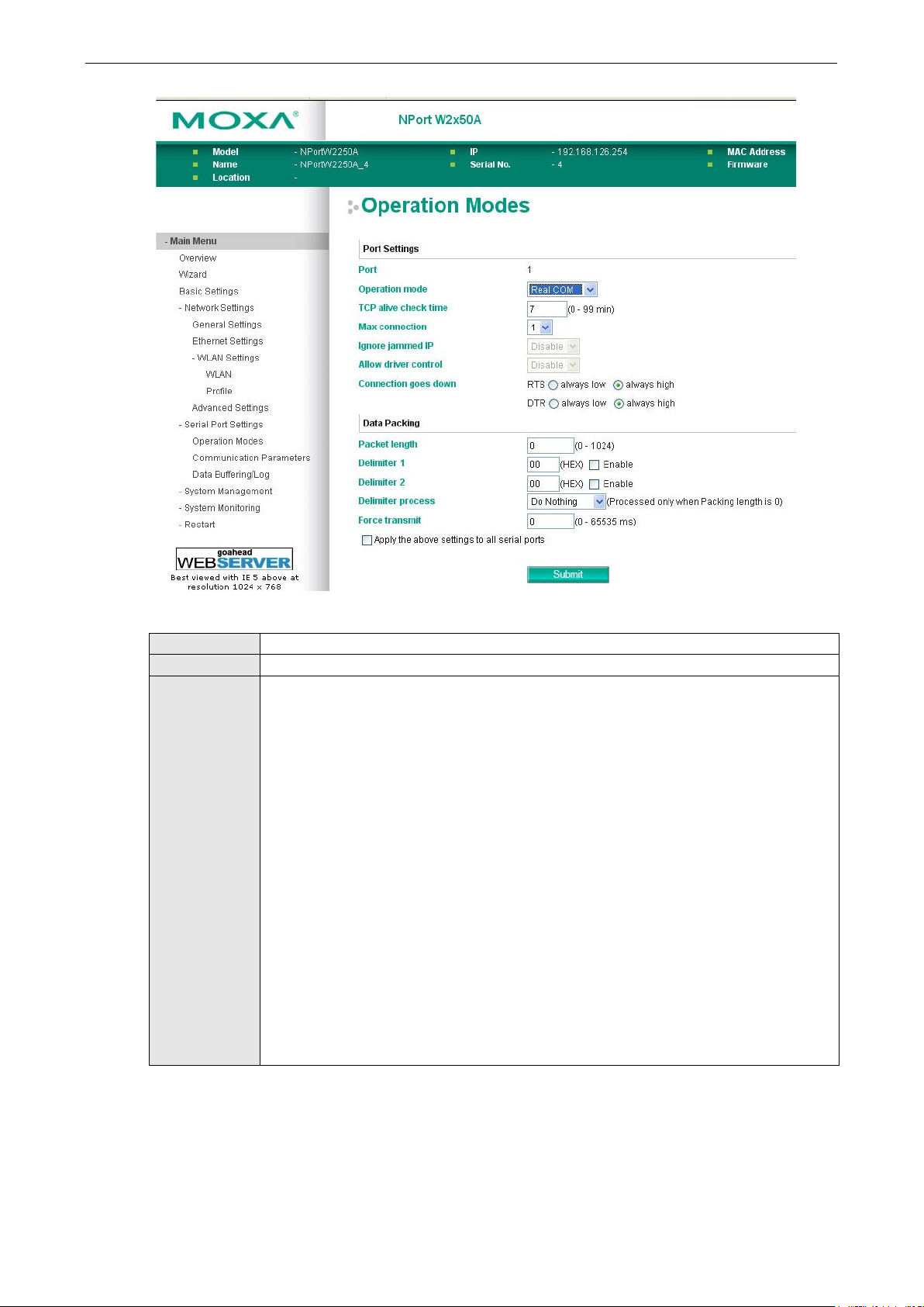
NPort W2150A/W2250A Series Web Console: Serial Port Settings
7-3
interact with network devices. Depending on how Application is configured, different options
available for configuration. For an introduction to the different operation modes, please refer
Operation Mode
Default RealCOM
Options RealCOM, RFC 2217, TCP Server, TCP Client, UDP, Pair_Master, Pair _Slave, EModem
Description Along with Application, this field specifies the serial port’s operation mode, or how it will
are available for Mode. Depending on how Mode is configured, additional settings will be
to Chapter 4. RealCOM: This serial port will operate in RealCOM mode.
RFC2217: This serial port will operate in RFC2217 mode.
TCP Server: This serial port will operate in TCP Server mode.
TCP Client: This ser ial port will operate in TCP Client mode.
UDP: This serial port will o perate in UDP mode.
Pair_Master: This serial port will operate in Pair Connectio n Ma ster mode.
Pair_Slave: This serial port will operate in Pair Connection Slave m ode.
EModem: This serial port will operate in Ethernet Modem mode.
Page 56

NPort W2150A/W2250A Series Web Console: Serial Port Settings
7-4
Settings for RealCOM Mode
When Operation Mode is set to RealCOM on a serial port’s Operation Modes page, you will be able to
configure additional settings including TCP alive check time, Max connection, Ignore jammed IP, Allow
driver Control, Connection goes down, Packet length, Delimiter 1, Delimiter 2, Delimiter process,
and Force transmit.
TCP Alive Check Time
Default 7 min
Options 0 to 99 min
Description This field specifies how long the NPort will wait for a response to “keep alive” packets before
closing the TCP connection. The NPo rt checks connection status by sending periodic “keep
alive” packets.
0: The TCP connection will remain open eve n if there is no response to the “keep alive”
packets.
1 to 99: If the remote host does not respond to the packet within the specif ied time, the
NPort will force the existing TCP connection to close.
Page 57

NPort W2150A/W2250A Series Web Console: Serial Port Settings
7-5
NPort
ATTENTION
When Max connection is 2 or greater, the serial port’s communication settings (i.e., baudrate, parity, data bits,
etc.) will be determined by the NPort. Any host that opens the COM port connection mu st use identical serial
communication settings.
Max connection
Default 1
Options 1 to 8
Description This field specifies the maximum number of connections that will be accepted by the serial
port.
1: Only one specific host can access this serial port, and the RealCOM driver on that host will
have full control over the port.
2 to 8: This serial port will allow the sp ecified number of connections to be opened
simultaneously. With simultaneous connections, the RealCOM driver will only provide a pure
data tunnel with no control ability. The serial communication will be determined by the
rather than by your application program. Application software that is based on the RealCOM
driver will receive a driver response of “success” when using any of the Win32 API functions.
The NPort will send data only to the RealCOM driver on the host. Data received from hosts will
be sent to the attached serial device o n a f irst-in-first-out basis.
Ignore jammed IP
Default Disable
Options Disable, Enab l e
Description This field specifies how an unresponsive IP address is handled when there are simultaneous
connections to the serial port.
Disable: All transmission will be suspended if one IP address becomes unresponsive.
Transmission will only resume when all hosts have responded.
Enable: Data transmission to the other hosts will not be suspended if one IP address becomes
unresponsive.
Allow driver control
Default Disable
Options Disable, Enab l e
Description This field specifies how the port will proceed if driver control commands are received from
multiple hosts that are conn ected to the port.
Disable: Driver cont rol commands will be ignored.
Enable: Control commands will be accepted, with the most recent command received taking
precedence.
Page 58

NPort W2150A/W2250A Series Web Console: Serial Port Settings
7-6
nt of data that is allowed to accumulate in the serial
packing with a single character; enable both Delimiter 1 and 2 to
ATTENTION
When
Connection goes down
Default always high
Options always low, always high
Description This field specifies what happens to the RTS and DTR signals when the Ethernet connection
goes down. For some applications, serial devices need to know the Ethernet link status
through RTS or DTR signals sent through the serial port.
Always low: The selected signal will change to low when the Ethernet connection goes down.
Always high The selected signal will remain high when the Ethernet connection goes down.
Packet length
Default 0
Options 0 to 1024
Description This field specifies the maximum amou
port buffer before sending.
0: Packet length is disregarded and data in the buffer will be sent as specified by the delimiter
settings or when the buffer is full.
1 to 1024: Data in the buffer will be sent as soon it reaches the specified length.
Delimiter 1 and 2
Default Disabled
Options Disabled, Enabled, 00 to FF
Description These fields are used to define special delimiter character(s) for data pack ing . Enable
Delimiter 1 to control data
control data packing with two charac ters received in sequence.
When these fields are enabled, serial data will accumulate in the serial port’s buffer until the
buffer is full or until the specified delimiter character(s) are received. For example, the
carriage return character could be used as a delimiter in order to transmit each sentence or
paragraph in a separate packet. Data will be packed according to Delimiter process.
Delimiters must be incorporated into the data stream at the so ftware or device level.
Delimiter 1 is enabled, Packet length must be set to 0.
Page 59

NPort W2150A/W2250A Series Web Console: Serial Port Settings
7-7
cluding delimiters.
Delimiter process
Default Do Nothing
Options Do Nothing, Delimiter + 1, Delimiter + 2, Strip Delimiter
Description This field specifies how data is packed when delimiter characters are received. This field has
no effect if Delimiter 1 is not enabled .
Do nothing: Data accumulated in the serial port’s buffer will be packe d, in
Delimiter + 1: One additional character must be received before the data in the serial port’s
buffer is packed.
Delimiter + 2: Two additional characters must be received before the data in the serial port’s
buffer is packed.
Strip Delimiter: Data accumulated in the serial port’s buffer will be packed, but the delimiter
character(s) will be stripped from the data.
Force transmit
Default 0 ms
Options 0 to 65535
Description This field controls data packing by the amount of time that elapses between bits of data.
When using this field, make sure that Inactivity time is disabled or set to a larger value.
Otherwise the connection may be closed before the data in the buffer can be tr a nsmitted.
0: If serial data is not received, the NPo rt will wait indefinitely for additional data.
1 to 65535: If serial data is not receive d for the specified amount of time, the data that is
currently in the buffer will be packed for network transmission. The optimal force transmit
time depends on your application, but it must be at least larger than one character interval
within the specified baudrate. For example, assume that the serial port is set to 1200 bps, 8
data bits, 1 stop bit, and no parity. In this case, the total number of bits needed to send a
character is 10 bits, and the time required to transfer one character is 8.3 ms, so the force
transmit time to be larger than 8.3 ms.
Page 60

NPort W2150A/W2250A Series Web Console: Serial Port Settings
7-8
Settings for RFC2217 Mode
When Operation Mode is set to RFC2217 on a serial port’s Operation Modes page, you will be able to
configure additional settings, including TCP alive check time, TCP port, Packet length, Delimiter 1,
Delimiter 2, Delimiter process, and Force transmit.
TCP alive check time
Default 7 min
Options 0 to 99 min
Description This field specifies how long the NPort will wait for a response to “keep alive” packets before
closing the TCP connection. The NPo rt checks connection status by sending periodic “keep
alive” packets.
0: The TCP connection will remain open even if there is no response to th e “keep alive”
packets.
1 to 99: If the remote host does not respond to the packet within the specif ied time, the
NPort will force the existing TCP connection to close.
TCP port
Default 4001
Options
Description This field specifies the TCP port number that the serial port will use to listen to connections,
and that other devices must use to contact the serial port.
Page 61

NPort W2150A/W2250A Series Web Console: Serial Port Settings
7-9
Delimiter 1 to control data packing with a single character; enable both Delimiter 1 and 2 to
l the
Packet length
Default 0
Options 0 to 1024
Description This field specifies the maximum amount of d a ta that is allowed to accumulate in the serial
port buffer before sending.
0: Packet length is disregarded and data in the buffer will be sent as specified by the delimiter
settings or when the buffer is full.
1 to 1024: Data in the buffer will be sent as soon it reaches the specified length.
Delimiter 1 and 2
Default Disabled
Options Disabled, Enabled, 00 to FF
Description These fields are used to define special delimiter character(s) for data pack ing . Enable
control data packing with two charac ters received in sequence.
When these fields are enabled, serial data will accumulate in the serial port’s buffer unti
buffer is full or until the specified delimiter character(s) are received. For example, the
carriage return character could be used as a delimiter in order to transmit each sentence or
paragraph in a separate packet. Data will be packed according to Delimiter process.
Delimiters must be incorporated into the data stream at the software or d evice level.
Delimiter process
Default Do Nothing
Options Do Nothing, Delimiter + 1, Delimit e r + 2, Strip Delimiter
Description This field specifies how data is packed when delimiter characters are received. This field has
no effect if Delimiter 1 is not enabled .
Do nothing: Data accumulated in the serial port’s buffer will be packed, including delimiters.
Delimiter + 1: One additional character must be received before the data in the serial port’s
buffer is packed.
Delimiter + 2: Two additional characters must be received before the data in the serial port’s
buffer is packed.
Strip Delimiter: Data accumulated in the serial port’s buffer will be packed, but the delimiter
character(s) will be stripped from the data.
Page 62
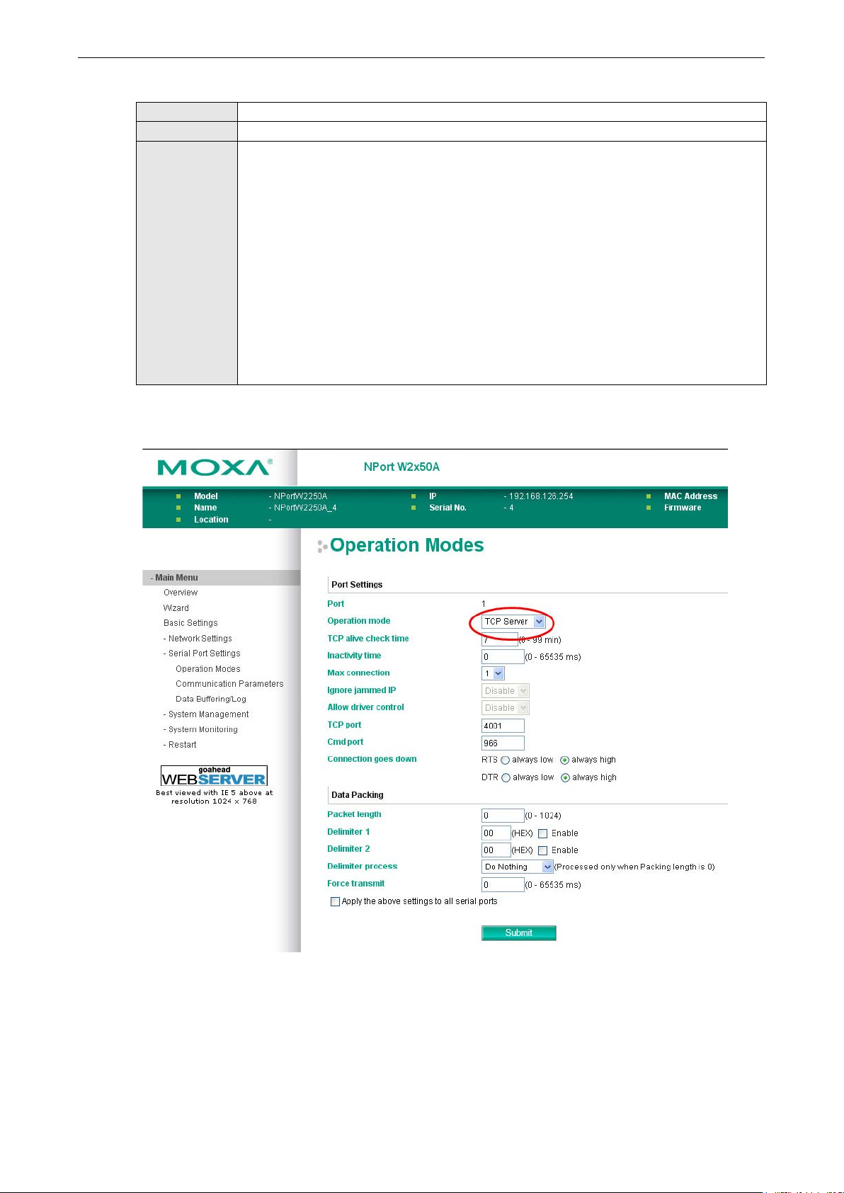
NPort W2150A/W2250A Series Web Console: Serial Port Settings
7-10
nterval
Force transmit
Default 0 ms
Options 0 to 65535
Description This field controls data packing by the amount of time that elapses between bits of data.
When using this field, make sure that Inactivity time is disabled or set to a larger value.
Otherwise the connection may be closed before the data in the buffer can be tr a nsmitted.
0: If serial data is no t received, the NPort will wait indefinite l y for additional data.
1 to 65535: If serial data is not received for the specified amo unt of time, the data that is
currently in the buffer will be packed for network transmission. The optimal force transmit
time depends on your application, but it must be at least larger than one character i
within the specified baudrate. For example, assume that the serial port is set to 1200 bps, 8
data bits, 1 stop bit, and no parity. In this case, the total number of bits needed to send a
character is 10 bits, and the time required to transfer one character is 8.3 ms, so the force
transmit time to be larger than 8.3 ms.
Settings for TCP Server Mode
When Operation Mode is set to TCP Server on a serial port’s Operation Modes page, you wi ll be able to
configure additional settings such as TCP alive check time, Inactivity time, Max connection, Ignore
jammed IP, Allow driver control, TCP port, Cmd port, Connection goes down, Packet length,
Delimiter 1, Delimiter 2, Delimiter process, and Force transmit.
Page 63

NPort W2150A/W2250A Series Web Console: Serial Port Settings
7-11
This field specifies the time limit for keeping the connection open if no data flows to or from
e
tions, the RealCOM driver will only provide a pure
The NPort will send data only to the RealCOM driver on the host. Data received from hosts will
ATTENTION
When Max connection is 2 or greater, the serial port’s communication settings (i.e., baudrate, parity, data bits,
etc.) will be determined by the NPort. Any host that opens the COM port connection mu st use identical serial
communi
TCP alive check time
Default 7 min
Options 0 to 99 min
Description This field specifies how long the NPort will wait for a response to “keep alive” packets before
closing the TCP connection. The NPo rt checks connection status by sending periodic “keep
alive” packets.
0: The TCP connection will remain open eve n if there is no response to the “keep alive”
packets.
1 to 99: If the remote host does not respond to the packet within the specif ied time, the
NPort will force the existing TCP connection to close.
Inactivity time
Default 0 ms
Options 0 to 65535 ms
Description
the serial device.
0: The connection will remain open even if data is never received. For many applications, the
serial device may be idle for long periods of time, so 0 is an appropriate setting.
1 to 65535: If there is no activity for the specified time, the connection will be closed. When
adjusting this field, make sure that it is greater than the Force transmit time. Otherwise, th
TCP connection may be closed befo re data in the buffer can be transmitted.
Max connection
Default 1
Options 1 to 8
Description This field specifies the maximum number of connections that will be accepted by the serial
port.
1: Only one specific host can access this serial port, and the RealCOM driver on that host will
have full control over the port.
2 to 8: This serial port will allow the sp ecified number of connections to be opened
simultaneously. With simultaneous connec
data tunnel with no control ability. The serial communication will be determined by the NPort
rather than by your application program. Application software that is based on the RealCOM
driver will receive a driver response of “success” when using any of the Win32 API functions.
be sent to the attached serial device o n a f irst-in-first-out basis.
cation settings.
Page 64

NPort W2150A/W2250A Series Web Console: Serial Port Settings
7-12
Ignore jammed IP
Default Disable
Options Disable, Enab l e
Description This field specifies how an unresponsive IP address is handled when there are simultaneous
connections to the serial port.
Disable: All transmission will be suspended if one IP address becomes unresponsive.
Transmission will only resume when all hosts have responded.
Enable: Data transmission to the other hosts will not be suspended if one IP address becomes
unresponsive.
Allow driver control
Default Disable
Options Disable, Enab l e
Description This field specifies how the port will proceed if driver control commands are received from
multiple hosts that are conn ected to the port.
Disable: Driver cont rol commands will be ignored.
Enable: Control commands will be accepted, with the most recent command received taking
precedence.
TCP port
Default 4001
Options 0 to 9999
Description This field specifies the TCP port number that the serial port will use to listen to connections,
and that other devices must use to contact the serial port.
Cmd port
Default 996
Options
Description This field specifies the TCP port number for listening to SSDK commands from the host.
The usage of other functions can be found in the subsection of RealCOM mode in page 7-4.
Connection goes down
Default always high
Options always low, always high
Description This field specifies what happens to the RTS and DTR signals when the Ethernet connection
goes down. For some applications, serial devices need to know the Ethernet link status
through RTS or DTR signals sent through the serial port.
Always low: The selected signal will change to low when the Ethernet connection goes down.
Always high The selected signal will remain high when the Ethernet connection goes down.
Page 65

NPort W2150A/W2250A Series Web Console: Serial Port Settings
7-13
Delimiter 1 to control data packing with a single character; enable both Delimiter 1 and 2 to
l the
ATTENTION
When
Strip Delimiter: Data accumulated in the serial port’s buffer will be packed, but the delimiter
Packet length
Default 0
Options 0 to 1024
Description This field specifies the maximum amount of d a ta that is allowed to accumulate in the serial
port buffer before sending.
0: Packet length is disregarded and data in the buffer will be sent as specified by the delimiter
settings or when the buffer is full.
1 to 1024: Data in the buffer will be sent as soon it reaches the specified length.
Delimiter 1 and 2
Default Disabled
Options Disabled, Enabled, 00 to FF
Description These fields are used to define special delimiter character(s) for data pack ing . Enable
control data packing with two charac ters received in sequence.
When these fields are enabled, serial data will accumulate in the serial port’s buffer unti
buffer is full or until the specified delimiter character(s) are received. For example, the
carriage return character could be used as a delimiter in order to transmit each sentence or
paragraph in a separate packet. Data will be packed according to Delimiter process.
Delimiters must be incorporated into the data stream at the software or d evice level.
Delimiter 1 is enabled, Packet length must be set to 0.
Delimiter process
Default Do Nothing
Options Do Nothing, Delimiter + 1, Delimit e r + 2, Strip Delimiter
Description This field specifies how data is packed when delimiter characters are received. This field has
no effect if Delimiter 1 is not enabled .
Do nothing: Data accumulated in the serial port’s buffer will be packed, including delimiters.
Delimiter + 1: One additional character must be received before the data in the serial port’s
buffer is packed.
Delimiter + 2: Two additional characters must be received before the data in the serial port’s
buffer is packed.
character(s) will be stripped from the data.
Page 66
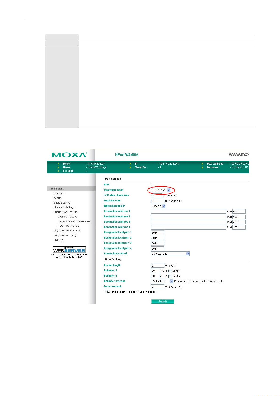
NPort W2150A/W2250A Series Web Console: Serial Port Settings
7-14
Force transmit
Default 0 ms
Options 0 to 65535
Description This field controls data packing by the amount of time that elapses between bits of data.
When using this field, make sure that Inactivity time is disabled or set to a larger value.
Otherwise the connection may be closed before the data in the buffer can b e tr a nsmitted.
0: If serial data is no t received, the NPort will wait indefinite l y for additional data.
1 to 65535: If serial data is not receive d for the specified amount of time, the data that is
currently in the buffer will be packed for network transmission. The optimal force transmit
time depends on your application, but it must be at least larger than one character interval
within the specified baudrate. For example, assume that the serial port is set to 1200 bps, 8
data bits, 1 stop bit, and no parity. In this case, th e total number of bits needed to send a
character is 10 bits, and the time required to transfer one character is 8.3 ms, so the force
transmit time to be larger than 8.3 ms.
Settings for TCP Client Mode
When Operation Mode is set to TCP Client on a serial port’s Operation Modes page, you will be able to
configure additional settings such as TCP alive check time, Inactivity time, Ignore jammed IP ,
Destination address 1-4, Designated local port 1-4, Connection control, and Packet length,
Delimiter 1, Delimiter 2, Delimiter process, and Force transmit.
Page 67

NPort W2150A/W2250A Series Web Console: Serial Port Settings
7-15
fore
from
ATTENTION
In TCP Client mode, up to 4 connections can be established between the ser ial port and TCP hosts. The
connection speed or throughput may be low if any one of the four connections is slow, since the one slow
connection will slow down the other 3
TCP Alive Check Time
Default 7 min
Options 0 to 99 min
Description This field specifies how long the NPort will wait for a response to “keep alive” packets be
closing the TCP connection. The NPo rt checks connection status by sending periodic “keep
alive” packets.
0: The TCP connection will remain op en even if there is no response to the “keep alive”
packets.
1 to 99: If the remote host does not respond to the packet within the specified time, the
NPort will force the existing TCP connection to close.
Inactivity time
Default 0 ms
Options 0 to 65535 ms
Description This field specifies the time limit for keeping the connection open if no data flows to or
the serial device.
0: The connection will remain open even if data is never received. For many applications, the
serial device may be idle for long periods of time, so 0 is an appropriate setting.
1 to 65535: If there is no activity for the specified time, the connection will be closed. When
adjusting this field, make sure that it is greater than the Force transmit time. Otherwise, the
TCP connection may be closed befo re data in the buffer can be transmitted.
Ignore jammed IP
Default Disable
Options Disable, Enab l e
Description This field specifies how an unresponsive IP address is handled when there are simultaneous
connections to the serial port.
Disable: All transmission will be suspended if one IP address becomes unresponsive.
Transmission will only resume when all hosts have responded.
Enable: Data transmission to the other hosts will not be suspended if one IP address becomes
unresponsive.
Destination address 1 to 4
Default
Options IP address and port (e.g., “192.168.1.1” and “4001”)
Description This field specifies the remote host(s) tha t will access the attached device. At least one
destination must be provided. T his field supports the use of domain names and names
defined in the host table.
connections.
Page 68

NPort W2150A/W2250A Series Web Console: Serial Port Settings
7-16
Designated local port 1 to 4
Default
Options 1 to 65535
Description This field specifies the TCP port number that will be used for data transmission with the serial
port.
Connection control
Default Startup/None
Options Startup/None, Any Character/None, Any Character/Inactivity Time, DSR On/DSR Off, DSR
On/None, DCD On/DCD Off, DCD On/None
Description This field specifies how connections to the device are established and closed.
Startup/None: The connection will be opened as the NPort starts up. The connection will only
be closed manually.
Any Character/None: The connection will be opened as soon as a character is received from
the attached device. The connec tion will only be closed manually.
Any Character/Inactivity Time: The connection will be opened as soon a s a character is
received from the attached device. The connection will be closed if no data is received for the
time specified in Inactivity tim e.
DSR On/DSR Off: The TCP connection is opened when the DSR signal is on, and closed when
the DSR signal is off.
DSR On/None: The TCP connection is opened when the DSR signal is on. The connection will
only be closed manually.
DCD On/DCD Off: The TCP connection is opened when the DCD signal is on, and closed when
the DCD signal is off.
DCD On/None: The TCP connection is opened when the DCD signal is on. The connection will
only be closed manually.
Packet length
Default 0
Options 0 to 1024
Description This field specifies the maximum amount of d a ta that is allowed to accumulate in the serial
port buffer before sending.
0: Packet length is disregarded and data in the buffer will be sent as specified by the delimiter
settings or when the buffer is full.
1 to 1024: Data in the buffer will be sent as soon it reaches the specified length.
Page 69

NPort W2150A/W2250A Series Web Console: Serial Port Settings
7-17
Delimiter 1 to control data packing with a single character; enable both Delimiter 1 and 2 to
ffer until the
ATTENTION
When
Strip Delimiter: Data accumulated in the serial port’s buffer will be packed, but the delimiter
Delimiter 1 and 2
Default Disabled
Options Disabled, Enabled, 00 to FF
Description These fields are used to define special delimiter character(s) for data pac king. Enab le
control data packing with two charac ters received in sequence.
When these fields are enabled, serial data will accumulate in the serial port’s bu
buffer is full or until the specified delimiter character(s) are received. For example, the
carriage return character could be used as a delimiter in order to transmit each sentence or
paragraph in a separate packet. Data will be packed according to Delimiter process.
Delimiters must be incorporated into the data stream at the software or d evice level.
Delimiter 1 is enabled, Packet length must be set to 0.
Delimiter process
Default Do Nothing
Options Do Nothing, Delimiter + 1, Delimit e r + 2, Strip Delimiter
Description This field specifies how data is packed when delimiter characters are received. This field has
no effect if Delimiter 1 is not enabled .
Do nothing: Data accumulated in the serial port’s buffer will be packed, including delimiters.
Delimiter + 1: One additional character must be received before the data in the serial port’s
buffer is packed.
Delimiter + 2: Two additional characters must be received before the data in the serial port’s
buffer is packed.
character(s) will be stripped from the data.
Force transmit
Default 0 ms
Options 0 to 65535
Description This field controls data packing by the amount of time that elapses between bits of data.
When using this field, make sure that Inactivity time is disabled or set to a larger value.
Otherwise the connection may be closed before the data in the buffer can b e tr a nsmitted.
0: If serial data is no t received, the NPort will wait indefinite l y for additional data.
1 to 65535: If serial data is not receive d for the specified amount of time, the data that is
currently in the buffer will be packed for network transmission. The optimal force transmit
time depends on your application, but it must be at least larger than one character interval
within the specified baudrate. For example, assume that the serial port is set to 1200 bps, 8
data bits, 1 stop bit, and no parity. In this case, the total number of bits needed to send a
character is 10 bits, and the time required to transfer one character is 8.3 ms, so the force
transmit time to be larger than 8.3 ms.
Page 70
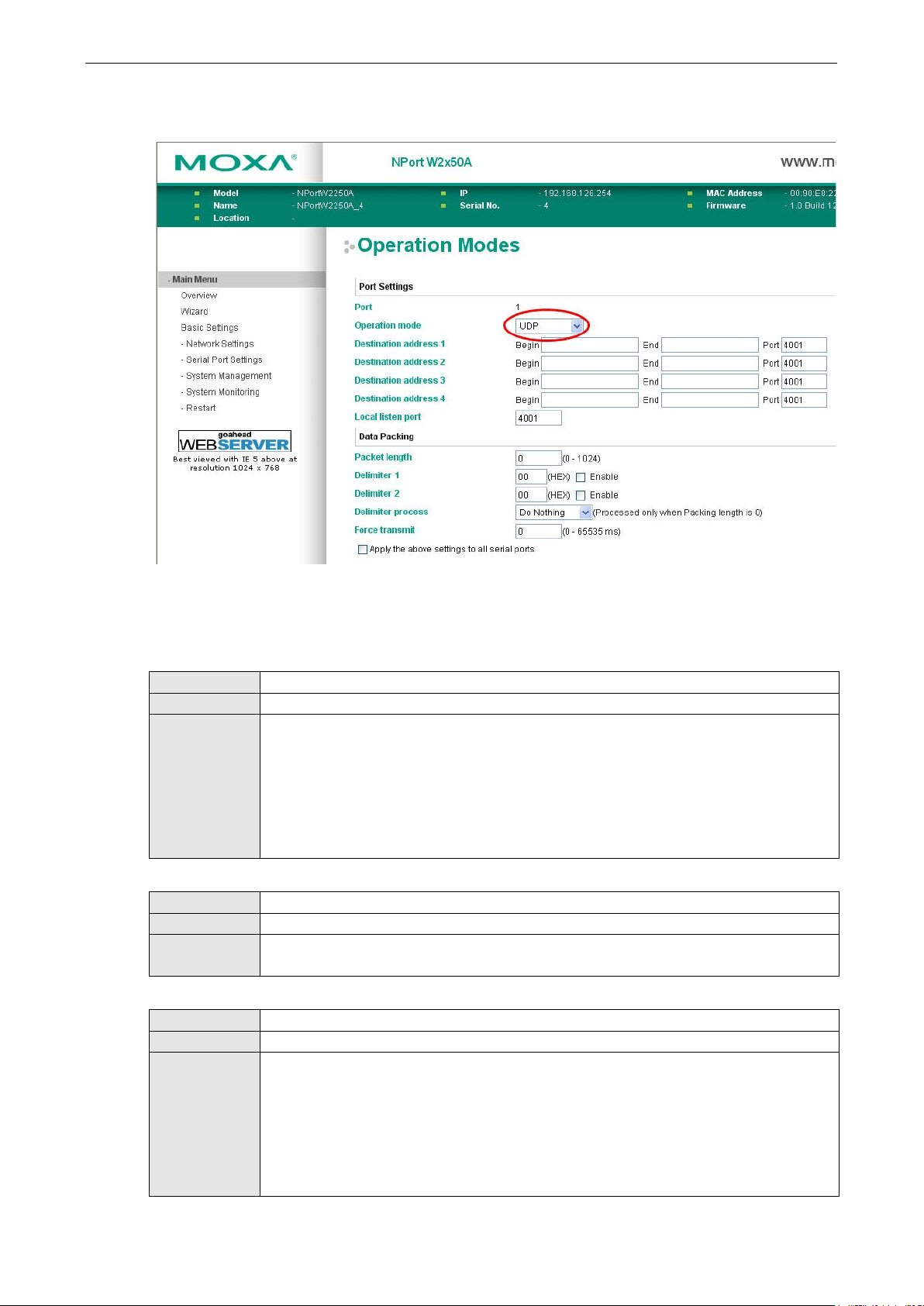
NPort W2150A/W2250A Series Web Console: Serial Port Settings
7-18
In UDP mode, you may specify up to 4 ranges of IP addresses for the serial port to connect
Settings for UDP Mode
When Operation Mode is set to UDP on a serial port’s Operation Modes page, you will be able to configure
additional settings such as Destination address 1 through 4, Local listen port, Packet length, Delimiter
1, Delimiter 2, Delimiter process, and Force transmit.
Destination address 1 to 4
Default
Options IP address range and port (e.g., “192.168.1.1” to “192.168.1.64” and “4001”)
Description
to. At least one destinatio n range must be provided.
The maximum selectable IP address range is 64 addresses. However, you can enter multicast
addresses in the Begin field, in the form xxx.xxx.xxx.255. For example, enter
“192.127.168.255” to allow the NPort to broadcast UDP packets to all hosts with IP
addresses between 192.127.168.1 and 192.127.168.254.
Local listen port
Default 4001
Options
Description This field specifies the UDP port that the NPort listens to and that other devices must use to
contact the attached serial dev ice.
Packet length
Default 0
Options 0 to 1024
Description This field specifies the maximum amount of d a ta that is allowed to accumulate in the serial
port buffer before sending.
0: Packet length is disregarded and data in the buffer will be sent as specified by the delimiter
settings or when the buffer is full.
1 to 1024: Data in the buffer will be sent as soon it reaches the specified length.
Page 71

NPort W2150A/W2250A Series Web Console: Serial Port Settings
7-19
Delimiter 1 to control data packing with a single character; enable both Delimiter 1 and 2 to
ATTENTION
When
Strip Delimiter: Data accumulated in the serial port’s buffer will be packed, but the delimiter
8
Delimiter 1 and 2
Default Disabled
Options Disabled, Enabled, 00 to FF
Description These fields are used to define special de limiter character(s) for data packing. Enable
control data packing with two charac ters received in sequence.
When these fields are enabled, serial data will accumulate in the serial port’s buffer until the
buffer is full or until the specified delimiter character(s) are received. For example, the
carriage return character could be used as a delimiter in order to transmit each sentence or
paragraph in a separate packet. Data will be packed according to Delimiter process.
Delimiters must be incorporated into the data stream at the software or d evice level.
Delimiter 1 is enabled, Packet length must be set to 0.
Delimiter process
Default Do Nothing
Options Do Nothing, Delimiter + 1, Delimit e r + 2, Strip Delimiter
Description This field specifies how data is packed when delimiter characters are received. This field has
no effect if Delimiter 1 is not enabled.
Do nothing: Data accumulated in the serial port’s buffer will be packed, including delimiters.
Delimiter + 1: One additional character must be received before the data in the serial port’s
buffer is packed.
Delimiter + 2: Two additional characters must be received before the data in the serial port’s
buffer is packed.
character(s) will be stripped from the data.
Force transmit
Default 0 ms
Options 0 to 65535
Description This field controls data packing by the amount of time that elapses between bits of data.
When using this field, make sure that Inactivity time is disabled or set to a larger value.
Otherwise the connection may be closed before the data in the buffer can be tr a nsmitted.
0: If serial data is no t received, the NPort will wait indefinite l y for additional data.
1 to 65535: If serial data is not receive d for the specified amount of time, the data that is
currently in the buffer will be packed for network transmission. The optimal force transmit
time depends on your application, but it must be at least larger than one character interval
within the specified baudrate. For example, assume that the serial port is set to 1200 bps,
data bits, 1 stop bit, and no parity. In this case, the total number of bits needed to send a
character is 10 bits, and the time required to transfer one character is 8 .3 ms, so the force
transmit time to be larger than 8.3 ms.
Page 72

NPort W2150A/W2250A Series Web Console: Serial Port Settings
7-20
Settings for Pair Connection Master Mode and Pair Connection Slave Mode
When Operation Mode is set to Pair Connection Master or Pair Connection Slave on a serial port’s
Operation Modes page, you will be able to configure addition al settings such as TCP alive check time,
Destination address and TCP port. A Pair Connection application involves one serial port communicating
over an IP network to another serial port as if the two serial ports were connected by a serial cable. Pair
Connection modes can be used to extend RS-232 transmission to unlimited distances.
An NPort device server is needed at both ends of the connection. The serial port at one end must be set to Pair
Connection Master mode, and the serial port at the other end must be set to Pair Connection Slave mode. It
does not matter which serial port is master and which serial port is slave.
Page 73

NPort W2150A/W2250A Series Web Console: Serial Port Settings
7-21
TCP alive check time
Default 7 min
Options 0 to 99 min
Description This field specifies how long the NPort will wait for a response to “keep alive” packets before
closing the TCP connection. The NPo rt checks connection status by sending periodic “keep
alive” packets.
0: The TCP connection will remain open even if there is no response to th e “keep alive”
packets.
1 to 99: If the remote host does not respond to the packet within the specif ied time, the
NPort will force the existing TCP connection to close.
Destination address
Default
Options IP address and port (e.g., “192.168.1.1” and “4001”)
Description This field specifies the IP address for the NPort at the opposite end of the Pair Connection,
and the TCP port number for communication with the serial port. The port number must
match with that serial port’s TCP port setting.
TCP port
Default 4001
Options
Description This field specifies the TCP port to use for communication with the attached serial device. The
serial port at the opposite end of the Pair Connection must use this port number to establish
the connection.
Settings for Ethernet Modem Mode
When Application is set to Ethernet Modem Mode, the NPort will accept AT commands such as “ A TD
192.127.168.1:4001” from the serial port. A TCP connection will then be requested from the specified remote
Ethernet Modem or PC. When the remote unit accepts this TCP connection, the NPort will return the “CONNECT
{baudrate}” signal to the serial port and will then enter data mode. Please refer to Appendix C for details on
Ethernet modem commands.
Page 74

NPort W2150A/W2250A Series Web Console: Serial Port Settings
7-22
you differentiate one serial port from another. It does
ATTENTION
Serial communication settings should match the attached serial d evice. Check the communication s ettings in
the user’s manual for your serial device.
TCP alive check time
Default 7 min
Options 0 to 99 min
Description This field specifies how long the NPort will wait for a response to “keep alive” packets before
closing the TCP connection. The NPo rt checks connection status by sending periodic “keep
alive” packets.
0: The TCP connection will remain open even if there is no response to the “keep alive”
packets.
1 to 99: If the remote host does not respond to the packet within the specif ied time, the
NPort will force the existing TCP connection to close.
TCP port
Default 4001
Options
Description This field specifies the TCP port to use for communication with the attach ed serial device.
Communication Parameters
The Communication Parameters page for each serial port is where serial communication settings are
specified, such as Baud rate, Data bits, and Stop bits.
Alias
Default
Options free text (e.g., “Secondary console connection”)
Description This is an optional free text field to help
not affect operation of the NPort device server.
Page 75

NPort W2150A/W2250A Series Web Console: Serial Port Settings
7-23
through the “Other” setting. When set to “Other”, you may manually enter a baudrate of your
provided to each serial port for both Tx and Rx directions. To prevent data loss during se rial
Baud rate
Default 115200
Options 50, 75, 110, 134, 150, 300, 600, 1200, 1800, 2400, 4800, 9600, 19200, 38400, 57600,
115200, 230400, 460800, 921600, Other
Description This field specifies the baudrate for the serial port. Nonstandard baudrates are supported
choice, up to 921600.
50 to 921600: The serial port will operate at the specified baudrate
Other: The serial port will operate at a baudrate that is manually entered by the user.
Parity
Default None
Options None, Odd, Even, Space, Mark
Description This field specifies the type of parity bit u sed for each character frame.
Data bit
Default 8
Options 5, 6, 7, 8
Description This field specifies the number of data bits used to encode each character of data.
Stop bit
Default 1
Options 1, 1.5, 2
Description This field specifies the number of stop bits used for each character frame.
Flow control
Default RTS/CTS
Options None, RTS/CT S , XO N/XOFF, DTR/DSR
Description This field specifies the type of flow control used by the serial port.
FIFO
Default Enable
Options Enable, Disable
Description This field specifies whether the serial port will use the built-in FIFO. A 128-byte FIFO is
communication, this should be set to Disabled if the attached serial dev ice does not have a
FIFO.
Interface
Default RS-232
Options RS-232, RS-422, RS-485 2-wire, RS-485 4-wire
Description This field specifies the type of interface the serial port will use.
Page 76

NPort W2150A/W2250A Series Web Console: Serial Port Settings
7-24
Data Buffering/Log
On the serial port’s Data Buffering/Log page, you can enable or disable Port buffering and Serial data
logging.
Port buffering
Default Disable
Options Enable, Disable
Description This field specifies whether the serial port will use port buffering when the network
connection (Ethernet or WLAN) is down. Port bufferi ng can be used in RealCOM mode, TCP
Server mode, TCP Client mode, and Pair Connection mode. For other modes, the port
buffering settings will have no effect.
Serial data logging(64K)
Default Disable
Options Enable, Disable
Description This field specifies whether data logs for the seria l p ort will be stored on system RAM. Each
serial port is allotted 64 KB for data logging. The data log is not saved when the NPort is
powered off.
Page 77

8
8. Web Console: System Management
The following topics are covered in this chapter:
Overview
System Management
Misc. Ne two r k Se tti ng s
Auto Warning Settings
Maintenance
Maintenance
Certificate
Page 78

NPort W2150A/W2250A Series Web Co n sole: System Management
8-2
Overview
This chapter explains how to configure all settings located under the System Management folder in the NPort
web console.
System Management
Misc. Network Settings
Accessible IP List
The Accessible IP List page is located under Misc. Network Settings in the System Management folder.
This page is used this restrict acce ss to the NPort by IP address. Only IP addresses on the list will be allow ed
access to the NPort. You may add a specific address or range of addresses by using a combination of IP address
and netmask, as follows:
To allow access to a specific IP address
Enter the IP address in the correspo n ding field; enter 255.255.255 .255 for the netmask.
To allow access to hosts on a specific subnet
For both the IP address and netmask, use 0 for the last digit (e.g., “192.168.1.0” and “255.255.255.0”).
To allow access to all IP addresses
Make sure that Enable the accessible IP list is not checked.
Page 79

NPort W2150A/W2250A Series Web Co n sole: System Management
8-3
Refer to the following table for more configuration examples.
Desired IP Range IP Address Field Netmask Field
Any host Disable Disable
192.168.1.120 192.168.1.120 255.255.255.255
192.168.1.1 to 192.168.1.254 192.168.1.0 255.255.255.0
192.168.0.1 to 192.168.255.254 192.168.0.0 255.255.0.0
192.168.1.1 to 192.168.1.126 192.168.1.0 255.255.255.128
192.168.1.129 to 192.168.1.254 192.168.1.128 255.255.255.128
SNMP Agent Settings
The SNMP Agent page is located under Misc. Network Settings in the System Management folder. This
page is used to configure the SNMP Agent on the NPort.
SNMP
Default Enable
Options Enable, Disable
Description This field enables or disables the SNMP Agent. If enabled, you will need to configure other
SNMP Agent settings. You will need to enter a community name under Read community
string.
Contact Name
Default
Options free text (e.g., “J Smith”)
Description This is an optional free text field that can be used to specify the SNMP emergency contact
name, telephone, or pager number.
Page 80

NPort W2150A/W2250A Series Web Co n sole: System Management
8-4
Location
Default
Options free text (e.g., “Building XYZ”)
Description This is an optional free text field that can be used to specify the location for SNMP agents such
as the NPort.
Read Community String
Default public
Options free text (e.g., “public community”)
Description This field specifies the read community str ing used for the SNMP Agent. This is a text
password mechanism that is used to weakly authenticate queries to agents of managed
network devices.
Write Community String
Default private
Options free text (e.g., “private community”)
Description This field specifies the write c ommunity string used for the SNMP Agent. This is a text
password mechanism that is used to weakly authenticate changes to agents of managed
network devices.
SNMP Agent Version
Default V1, V2c, V3
Options V1, V2c, V3 / V1, V2c / V3 only
Description This field specifies which version(s) of SNMP to support.
Read Only User Name
Default rouser
Options free text (e.g., “guest”)
Description This field specifies a user name to use for r ea d only access.
Read Only Authentication Mode
Default Disable
Options Disable, MD5 , SH A
Description This field specifies the type of authentica tion to use for read-only access.
Read Only Password
Default
Options free text (e.g., “password123”)
Description This field specifies the password that users must enter for read-only access, if read only
authentication is enabled.
Read Only Privacy mode
Default Disable
Options Disable, DES_ C BC
Description This field specifies whether DES_CBC data encryption will be used during read-only access.
Read Only Privacy
Default
Options free text (e.g., “read o n ly key”)
Description This field specifies the encryption key f or read-only access, if read-only privacy is enabled.
Read/Write User Name
Default rwuser
Options free text (e.g., “admin”)
Description This field specifies a user name to use for read/write access.
Page 81
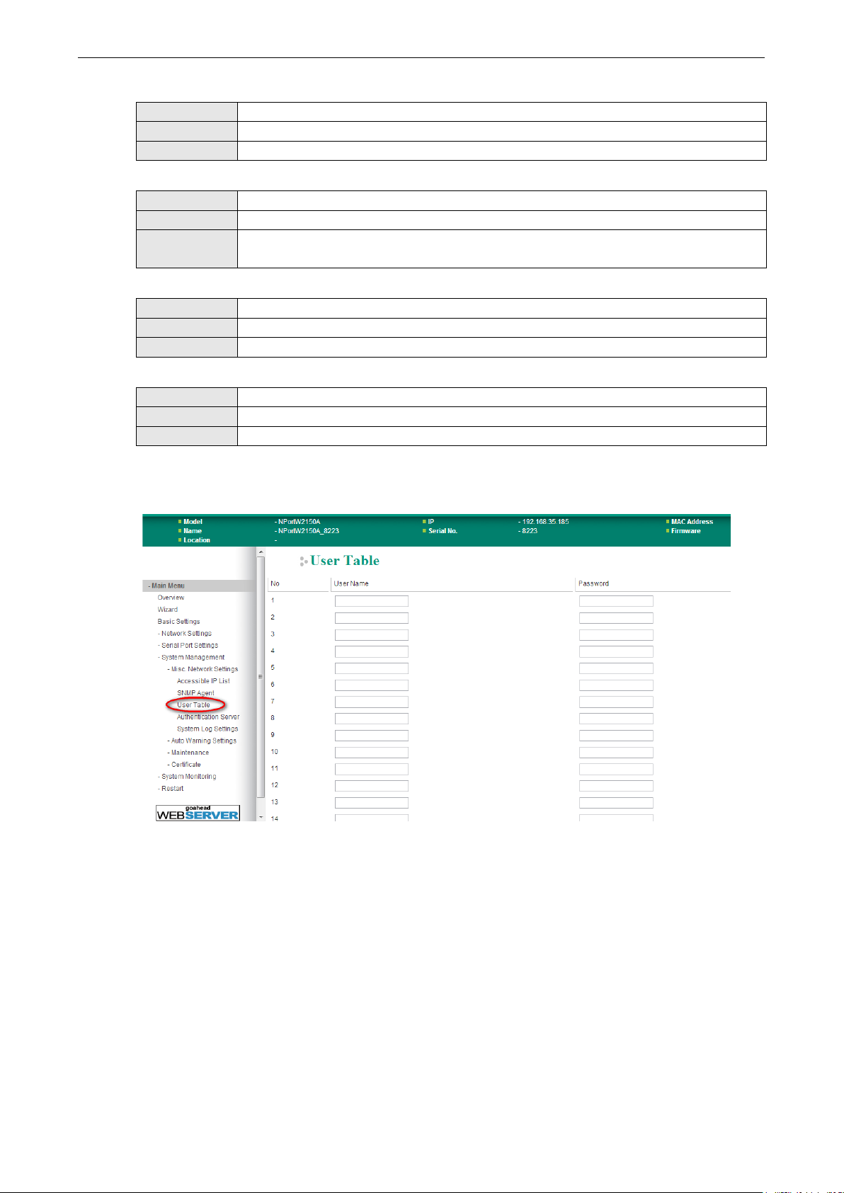
NPort W2150A/W2250A Series Web Co n sole: System Management
8-5
Read/Write Authentication Mode
Default Disable
Options Disable, MD5 , SH A
Description This field specifies the type of authentica tion to use for read/write access.
Read/Write Password
Default
Options free text (e.g., “password123”)
Description This field specifies the password that users must enter for read/write access, if read only
authentication is enabled.
Read/Write Privacy mode
Default Disable
Options Disable, DES_ C BC
Description This field specifies whether DES_CBC data encryption will be used during read/write access.
Read/Write Privacy
Default
Options free text (e.g., “read w rite key”)
Description This field specifies the encryption key for read/write access, if read-/write privacy is enabled.
User Table
The NPort User Table can be used to authenticate users for reverse terminal access and is useful if you do not
have an external RADIUS server for authentication. The NPort U ser Table stores up to 64 entries, with fields for
User Name and Password.
Page 82

NPort W2150A/W2250A Series Web Co n sole: System Management
8-6
Authentication Server
RADIUS server: If you are using a RADIUS server for user authentication, enter its IP address here.
RADIUS key: If you are using a RADIUS server for user authentication, enter its password here.
UDP port (default=1645): If you are using a RADIUS server, enter its UDP port assignment here.
RADIUS accounting: Use this field to enable or disable RADIUS accounting.
System Log Settings
The System Log page is located under Misc. Network Settings in the System Management folder. This is
where you select the type of events that will be logged by the NPort.
Group Event
System System Cold Start, System Warm Start
Network DHCP/BOOTP, Get IP/Renew, Mail Fail, NTP Conne ct Fail, IP Conflict, Network Link Down
Config Login Fail, IP Changed, Password Changed, Firmware Upgrade, SSL Certificate Import,
Config Import, Config Export, Wireless Certificate Import, Serial Data Log Export
Op Mode Connect, Disconnect, Restart
Page 83

NPort W2150A/W2250A Series Web Co n sole: System Management
8-7
Auto Warning Settings
Event Settings
The Event Settings page is located under Auto Warning Settings in the System Management folder. This
is where you specify how the NPort will notify you of system and configuration events. Depending on the event,
different options for notification are available, as shown above. Mail refers to sending an e-mail to a specified
address. Trap refers to sending an SNMP tra p .
Event Description
Cold start The NPort was powered on, or was restarted after a firmware upgrade.
Warm start The NPort restarted without powering off.
Console login auth fail An attempt has been mad e to open the web, Telnet, or serial console, but the
password was incorrect.
IP changed The IP address has been changed.
Password changed The password to the console has been changed.
Page 84

NPort W2150A/W2250A Series Web Co n sole: System Management
8-8
ATTENTION
SNMP indicates a change in DCD or DSR signals but does not differentiate between the two. A change in either
signal from “
” is indicated by “link
down.”
Serial Event Settings
The Serial Event Settings page is located under Aut o Wa rn ing Settings in the System Management
folder. This is where you specify how the NPort will notify you of DCD and DSR events for each serial port. Mail
refers to sending an e-mail to a specif ied address. Trap refers to sending an SNMP trap.
A change in the DCD (Data Carrier Detect) signal indicates that the modem connection status has changed. If
the DCD signal changes to low, it in dicates that the connection line is down. A change in the DSR (Data Set
Ready) signal indicates that the data communication equipment is powered off. If the DSR signal changes to
low, it indicates that the data com munication equipment is powered d own.
–” to “+” is indicated by “link up” and a change in either signal from “+” to “–
Page 85

NPort W2150A/W2250A Series Web Co n sole: System Management
8-9
ATTENTION
Consult your network administrator or ISP for the mail server settings to use for your network. If these settings
are not configured correctly, e
E-mail Alert
The E-mail Alert page is located under Auto Warning Settings in the System Management folder. This is
where you specify how and where e-mail is sent when e-mail is used for automatic notification of system and
serial port events.
-mail notification may not work properly.
Mail Server (SMTP)
Default
Options free text (e.g., “192.168.3.3”)
Description This field specifies the IP address of the mail server that will be used when sending automatic
warning e-mails. If the mail server requires authentication, select “My server requires
authentication” and enter the user na me and password.
From e-mail address
Default
Options free text (e.g., “jsmith@xyz.com”)
Description This field specifies the e-mail address that will be listed in the e-mail’s “From” field.
To e-mail address 1 to 4
Default
Options free text (e.g., “admin@abc.com”)
Description These fields specify the destination e-ma il address(es) for the automatic e-mail warnings.
Page 86

NPort W2150A/W2250A Series Web Co n sole: System Management
8-10
SNMP Trap
The SNMP Trap page is located under Auto Warning Settings in the System Management folder. This is
where you specify the SNMP trap settings to use for automatic notification of system and serial port events.
SNMP Trap Server IP
Default
Options IP address (e.g., “192.168.5.5”)
Description This field specifies the IP address of the SNMP trap server that will receive SNMP traps.
Trap Version
Default v1
Options v1, v2c
Description This field specifies the SNMP trap version to use.
Trap Community
Default
Options free text (e.g., “public access”)
Description This field specifies the SNMP trap community.
Page 87

NPort W2150A/W2250A Series Web Co n sole: System Management
8-11
Maintenance
Console Settings
The Console Settings page is located under Maintenance in the System Management folder. This is where
you enable or disable access to the various NPort configuration con soles, as well as the behavior of the reset
button. You may modify HTTP console, HTTPS console, Telnet console, SSH console, Serial Console,
and Reset button.
HTTP Console
Default Enable
Options Enable, Disable
Description This field enables or disables access to the HTTP (web) console.
HTTPS Console
Default Enable
Options Enable, Disable
Description This field enables or disables access to the HTTPS (web) console.
Telnet Console
Default Enable
Options Enable, Disable
Description This field enables or disables access to the Telnet console.
SSH Console
Default Enable
Options Enable, Disable
Description This field enables or disables access to the SSH console.
Serial Console
Default Enable
Options Enable, Disable
Description T his field enables or disables access to the serial console.
Page 88

NPort W2150A/W2250A Series Web Co n sole: System Management
8-12
that the
Reset Button
Default Always Enable
Options Always Enable, Disable after 60 sec
Description This field specifies the behavior of the hardware reset button.
Always Enable: The reset button will be operate as usual.
Disable after 60 sec: The reset button will only be effective for the first 60 seconds
NPort is powered on.
Maintenance
Ping
The Ping page is located under Maintenance in the System Ma n a gement folder. It provides a convenient
way to test an Ethernet connection or verify an IP address. Enter the IP address or domain name in the
Destination field an d click [Activate]. The results will be displayed immediately.
Firmware Upgrade
The Firmware Upgrade page is located under Maintenance in the System Management fo lder. This is
where you can update the NPort firmware. After obtaining the latest firmware from www.moxa.com, se lect or
browse for the firmware file in the Select firmware file field. Before clicking [Submit], it is a good idea to
save the NPort configuration using the Configuration Export page, since the firmware upgrade process may
cause all settings to revert to factor y defaults.
Page 89

NPort W2150A/W2250A Series Web Co n sole: System Management
8-13
Configuration Import
The Configuration Import page is located under Maintenance in the System Management folder. This is
where you can load a previously saved or exported configuration. Select or browse for the configuration file in
the Select configuration file field. If you also wish to import the IP configuration (i.e., IP address, netmask,
and gateway), make sure that Import all configurations including IP configurations is checked.
Configuration Export
The Configuration Export page is located under Maintenance in the System Management folder. This is
where you can save the NPort’s current configuration to a file on the local host . Click [Download] to begin the
process. A window should appear asking you to open or save the configuration text file.
Page 90

NPort W2150A/W2250A Series Web Co n sole: System Management
8-14
Load Factory Default
The Load Factory Default p a ge is located under Maintenance in the System Management folder. Click
[Submit] to reset all settings to the factory defaults. You can preserve the NPort’s existing IP settings (i.e., IP
address, netmask, gateway, WLAN profile, and all certificates) by making sure Keep IP settings is checked
before clicking [Submit].
Change Password
The Change Password page is located under Maintenance in the System Management folder. To change
the password, choose the account name first, and then enter the old password in the Old password field.
Leave this blank if the NPort is not currently password-protected. Enter the new password twice, once in the
New password field and once in the Confirm password. Leave these fields blank to remove password
protection.
Page 91

NPort W2150A/W2250A Series Web Co n sole: System Management
8-15
ATTENTION
If you forget the password, the ONLY way to configure the NPort is by loading the factory defaults with the rese t
button. All settings will be lost.
Before setting the password, you may want to first export the conf
then be easily imported back into the NPort if necessary.
Certificate
Ethernet SSL Certificate Import
iguration to a file. Your configuration can
The Ethernet SSL Certificate Import page is located under Certificate in the System Management folder.
This is where you can load the Ethernet SSL certificate. Select or browse for the certificate file in the Select SSL
certificate/key file field.
WLAN SSL Certificate Import
Page 92

NPort W2150A/W2250A Series Web Co n sole: System Management
8-16
The WLAN SSL Certificate Import page is located under Certificate in the System Management folder. By
default, the WLAN SSL certificate is a u tomatically generated by the NPort ba sed on the IP address of the
wireless interface. You can also import a certificate. Select or browse for the certificate file in the Select SSL
certificate/key file field.
WPA Server Certificate Import
The WPA Server Certificate Import page is located under Certificate in the System Management folder.
This is where you can load the WPA server certificate. Select or browse for the certificate file in the Select WPA
server certificate file field.
You must install the trusted server certificate from the RADIUS serv er in order to enable Verify server
certificate in the WLAN Security settings. This certificate will then be used by the NPort to authenticate the
RADIUS server.
Page 93

NPort W2150A/W2250A Series Web Co n sole: System Management
8-17
WPA User Certificate Import
The WPA User Certificate Import page is located under Certificate in the System Management folder.
This is where you can load the WPA user certificate. Select or browse for the certificate file in the Select WPA
user certificate file field.
The user certificate of the NPort must be installed in the RADIUS server when the NPort uses WPA (WPA2)/TLS.
The trusted server certificate of the RADIUS server must also be installed in the NPort.
WPA User Key Import
The WPA User Key Import page is located under Certificate in the System Management folder. This is
where you can load the WPA user certificate. Select or browse for the user private key file in the Select WPA
user privacy key file field and enter the Password for the private key.
Page 94

NPort W2150A/W2250A Series Web Co n sole: System Management
8-18
The user private key of the NPort must be installed in the RADIUS server w h en the NPort uses
WPA(WPA2)//TLS. The trusted serv er certificate of RADIUS server must also be installed on the NPort.
Certificate/Key Delete
The Certificate/Key Delete page is located under Certificate in the System Management folder. This page
is where you can delete certificate s o r WPA keys that have been installed o n the model. When you click
[Submit], any certificate or k ey that has been set to “Delete” will be deleted from the NPort.
Page 95

9
9. Web Console: System Monitoring
The following topics are covered in this chapter:
Overview
System Monitoring
Serial Status
System Status
Page 96

NPort W2150A/W2250A Series Web Console: System Monitoring
9-2
Overview
This chapter explains how to use the System Monitoring functions on the NPort web console. These functions
allow you to monitor many different aspects of operation.
System Monitoring
Serial Status
Serial to Network Connections
The Serial to Network Connections page is located under Serial Status in the System Monitoring folder.
On this page, you can monitor the current operation mode and host connection status for each serial port.
Page 97

NPort W2150A/W2250A Series Web Console: System Monitoring
9-3
Serial Port Status
The Serial Port Status page is located under Serial Status in the System Monitoring folder. On this page,
you can monitor the signal and data transmission status for each serial port.
TxCnt: number of Tx packets (to device) for the current connection
RxCnt: number of Rx packets (from device) for the current connection
TxTotalCnt: number of Tx packets since the NPort was powered on
RxTotalCnt: number of Rx packets since the NPort was powered on
Serial Port Error Count
The Serial Port Error Count page is located under Serial Status in the System Monitoring folder. On this
page, you can view the current number of frame, parity, overrun and break errors for each serial port.
Page 98

NPort W2150A/W2250A Series Web Console: System Monitoring
9-4
Serial Port Settings
The Serial Port Settings page is located under Serial Status in the System Monitoring folder. On this page,
you can view the current communication settings for each serial port.
System Status
Network Connections
Page 99

NPort W2150A/W2250A Series Web Console: System Monitoring
9-5
The Network Connections page is located under System Status in the System Monitoring folder. On this
page, you can view the current status of any network connection to the NPort.
Serial Data Log
Data logs for each serial port can be viewed in ASCII or HEX format. After selecting the serial p ort and format,
you may click Select all to select the entire log if you wish to copy and paste the contents into a text file. The
Clear log and Refresh buttons allow you to clear or refresh the log contents.
The Serial Data Log page is located under System Status in the System Monitoring folder. This is where
you can download the current data log for a serial port. Select the desired serial port in the Select port field.
Select the desired data format in the Download format field. Click [Clear log] to clear the log contents.
The data log includes all data sent or received by the specified serial port since the NPort was powered on. The
maximum size of the log is 64 KB.
Page 100
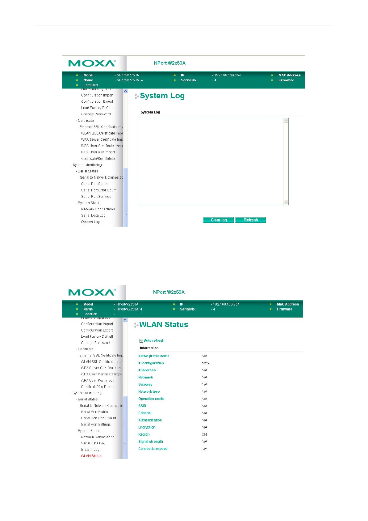
NPort W2150A/W2250A Series Web Console: System Monitoring
9-6
System Log
The System Log page is located under System Status in the System Monitoring folder. This is where you
can view the log of NPort system events. Click [Clear log] to clear the log contents. Click [Refresh] to refresh
the log contents.
WLAN Status
The WLAN Status page i s located under System Status in the System Monitoring folder. This is where you
can view the current WLAN settings and status.
 Loading...